Battery startup behaviour

241 views
Skip to first unread message

B0bD

unread,
Jul 16, 2021, 4:46:13 PM7/16/21
to electrodacus
Finally got everything working properly, and had a bit of sun so that the battery charged up.
During the charging, at a rate up to 90 amps, ( btw the battery is 3P8S, total 840AH), the cell voltages kept close together; the display showed the BMS balancing doing its thing.
Then, as 100% is approached, cell 8 sort of accelerates and reaches the 3.55V charger cutoff. Over the last 10 minutes before the charger is shut off, the dV rises from less then 50 mV to 200.  10 minutes after the charger is shut off, the dV is back under 25mV. 
There has only been two full charges so far, so I am not sure whether or not to be concerned about this.
A snapshot of the data is below, with the highest voltage cell highlighted.
Up to the few minutes shown below, the highest voltage cell is more or less evenly distributed among the 8, on a minute interval.


Capture.JPG

I have measured the resistance and the dV from each busbar to the battery terminal, and they are pretty consistent, and low.  Prior to assembly, the cell IR's measured consistent within 0.03 milliohm.

I have the charge controller set at 29 volts, and it is under control of the SBMSO, so no absorb or float.

Has anyone seen a similar characteristic?

Dacian Todea

unread,
Jul 16, 2021, 4:59:44 PM7/16/21
to electrodacus
Yes all that is normal.  The up to 200mV cell delta is in big part due to cell balancing current so the delta is not real just what the SBMS0 can read while cell balancing is active due to voltage drop on cell monitoring wires.
The closer a cell is to full 100% charge the faster the voltage will increase so even less than 0.1% delta between cells will make so that one cell gets first to 3.55V in your case cell 8 with cell 7 fairly close behind.

B0bD

unread,
Jul 16, 2021, 5:29:06 PM7/16/21
to electrodacus
Thanks - that is helpful.
I am impressed at how well the balancing holds the voltages, even on this initial charge, and without going through a preassembly balancing of any sort.
Sort of makes all the3 discussion about high current active balancing a bit moot, at least in a low C rate stationary setup.

B0bD

unread,
Jul 26, 2021, 4:11:56 PM7/26/21
to electrodacus
Some follow-up - Is the following behaviour typical or something to be concerned about?
There have been several charge cycles, with consistent outcomes.
The data is at 10 second intervals.
Up to 99%SOC cell to cell voltage is close - within 25mv or so. 
About 5 minutes before reaching 100%, the dV starts to increase, with cell 8 ramping up faster than the rest and stopping the charging.
After charging stops, cell voltages start to fall, with cell 8 falling faster.
dV reduces to 25mv after about 30 minutes, and voltages stay close until the next charge cycle.
Its hard to see in the chart, but the lowest cells reach 3.45 volts, and look like they have started into the knee.

It seems to me that this is all OK - that there will always be one cell somewhat ahead of the rest, but if anyone has charging cycle data from their battery for comparison I'd sure appreciate it.


Capture.JPG

Dave Festing

unread,
Jul 26, 2021, 4:28:08 PM7/26/21
to electrodacus
For the SBMS0 I see the same.  What I did observe was that my older SBMS60 didn't do this.  I would consistently get to 28.5V whereas now I get to 27.5V to 27.8V.  Apparently, it is normal behaviour and the system has been working well.

Dacian Todea

unread,
Jul 27, 2021, 3:59:17 PM7/27/21
to electrodacus
There is absolutely nothing abnormal in that graph. That is expected for any LiFePO4 battery. Cell 8 is just your cell with slightly lower capacity and there will always be a cell that is just slightly different.
If say you replace cell 8 with a higher capacity cell then it will be that orange cell that will be the first to fully charge and if you replace that it will be the green one and so on.
There will always be a cell to finish first by a few seconds.  

And Dave it is the same for any SBMS model you just did not noticed before or had different settings and did not notice because of that.


The important part is that as soon as cell are close to full you can see in the graph above 3.4 to 3.45V the voltage will increase super fast almost exponential since the cell can no longer accept any electrons. Since there are small difference between cells there will always be a cell to get first there even if is just a few second sooner it looks like a huge difference if you look at the voltage.
And of course it will also drop in voltage very fast after the charging is stopped as cell can not stay at that high voltage level.

There is nothing abnormal about your battery and your battery is perfectly balanced as perfect as it can be for a real battery and not an ideal theoretical one.

B0bD

unread,
Jul 27, 2021, 4:07:20 PM7/27/21
to electrodacus
Thanks for the comments - I can now quit obsessing over this and stop spending time gathering data.
I really appreciate all the helpful input from the forum as I took this plunge into the LFP arena.

Now I just need someone to take a huge lead acid battery off my hands.

Dave Festing

unread,
Jul 28, 2021, 12:41:58 AM7/28/21
to electrodacus
Default factory settings both units, except GPIO.  I have several hundred SBMS60 logs which show multiple charges on sunny days that get to 28.0 to 28.5V  Generally getting higher on days which had 3, 4 or 5 cycles.

With a default SBMS0 you only get one high charge but in the range 27.4 to 27.7.V and with noticeable jumping around.  I may have not noticed jumping around on the SBMS60, but for the days where you could get up to 28.5V of course there wouldn't be any.

One change was the battery sensing cable.  On the SBMS0 install I used the supplied cable compared with slightly shorter wire connections (100-300mm) for the SBMS60 install.

Unfortunately, when I changed to the SBMS0 I also moved the system inside so there could be subtle changes in where things are positioned and where things are grounded.

The new system has not missed a beat, so I am pleased with how things are working.

Dacian Todea

unread,
Jul 28, 2021, 12:54:56 PM7/28/21
to electrodacus
Dave,

The SBMS60 default may have been 3.6V per cell (do not remember) Also SBMS60 will have stopped charging in 1 second after any cell will have exceeded the set limit say 3.6V
The SBMS0 is set at 3.55V for 6 seconds consecutive (may be different if you changed that).  What you call jumping around has to do with cell balancing and both will have worked exactly the same if cell balancing was enabled.
I remember you had a hydro-generator and that may not have been properly controlled by the SBMS60 thus the possibility to get to 28.5V.
The much sorter cell balancing connection will have resulted in less voltage drop during cell balancing.
The graph with cell voltages shown above is perfectly typical of how SBMS0 and SBMS60 (assuming same settings) will have worked. Also the cells are perfectly fine and balanced.   

Allen Tindall

unread,
Jun 10, 2023, 11:56:59 PM6/10/23
to electrodacus
My SBMS0 has been installed (4S LPH configuration) in a self built RV and has been working great for several years.  It has mostly been charged by solar supplying about 20 amps and has always showed 99% SOC when fully charged.  About 2 weeks ago, I noticed the SOC to be 100% and holding.  I tried to access the monitoring by pressing the buttons and could not get the SBMS0 to respond.  Disconnecting the 12 pin plug and reconnecting resulted in I think the monitoring line just blinking.  I decided to replace it with my spare.  After installation I temporally changed ExIO3 and ExIO4 to Type 0 to test and all items turned off as expected.  I changed ExI03 to Type 2 and ExI04 to Type 1.   Using a Victron Multi I charged the batteries at a 90 Amp rate to reach 100% SOC.  I was not in the RV at 100% SOC.  When I returned to the RV, the charging turned off as expected, but the I03 also turned off so also no lighting.  After awhile, lighting turned on.  I changed the Multi charging rate to 10 Amps and watched the monitoring screen closely.  Cell balancing looked normal.  As soon as the high cell reached just above 3.5V everything turned off again.  The SBMS screen flashed to the login screen of 3 buttons but the buttons were flashing on and off.  Some times the Monitoring line would flash.  After awhile the screen would slowly return to normal.  I temporally turned on the Multi Charger and verified that the charging would not restart until below 80% SOC.  Thinking that the high cell might have reached overvoltage lock, I changed the overvoltage setting to 3.50V from 3.55V.  Retesting had the same results.  Since it seems that both of the SBMS0's are possibly behaving the same, I do not believe that the SBMS0's are the problem but I do not know what to look at.  I have checked all of the wiring connections and everything is tight.  Any suggestions.  Basically I am trying to determine what would cause EXI03 to turn off and the SBMS0 screen to flash various screens when the charged reaches the Over Voltage setting instead of just turning off EXI04.  I have the older version of the SBMS0 and would like to buy new ones once they are available, but I need to make sure I fix this problem first.

Dacian Todea (electrodacus)

unread,
Jun 11, 2023, 1:08:24 PM6/11/23
to electrodacus
Allen,

What do you mean exactly by monitor line blinking ?
The disconnecting of the Loads after full charge means that Over voltage Lock threshold was exceeded but that is set at 3.7V by default so that should not be the case unless you changed that to maybe 3.55V
So "Overvoltage" should be set at 3.55V as default but "Overvoltage Lock" should be set at 3.70V as it is as default.
If "Overvoltage lock" is exceeded even for a fraction of a second both charge and discharge is disabled.
You may also want to check your wiring maybe something become loose. The only way that SBMS0 was ever damaged is by connecting the battery with reverse polarity (not your case) and second and most common is by incorrectly installing the current shunts. Current shunts need to be installed directly to battery with a short 30 to 40cm max long wire and there should be nothing between Battery+ terminal and shunt.

If you are saying that  SBMS0 showed the buttons lock screen without you pushing any buttons then you have a problem with the capacitive buttons and most probable will be that the SBMS0 is not fully closed (maybe when you installed the SBMS0 on some front panel you did not properly tithed the screws so the spring contacts from front panel's do not reach the main PCB).

Allen Tindall

unread,
Jun 14, 2023, 11:27:56 PM6/14/23
to electrodacus
I am not sure what is happening.  I have 2 of the older SBMS0 devices.  I am planning on purchasing 2 of the SBMS0v03 devices as soon as they are available, but I would like to make sure the system is working before I install the new devices.  I plan to redo some of the installation when I install the new devices.  When I originally installed the SBMS0 I chose the location based on accessibility of the 12 pin plug on the back side.  This resulted in extending the ribbon wire to a total length of about 3 meters.  I cut the ribbon wire short and extended it with 2 each 24 gauge Cat 5 shielded cables so that each of the wires was doubled.  The system has been working perfectly for about 2 years and even with the problem I am having, the cell balancing appears to be working correctly so I do not believe that the extra length is related.  I have figured out that I can locate the SBMS0v03 within the length of the ribbon wire if I install an 8 pole plug (need 7 wires for 4s configuration) in the ribbon wire near the batteries.  The extra plug is required because the 12 pin plug on the back side of the SBMS0v03 will not be accessible.

I am not sure what is happening because too many changes happen too quickly to observe and remember.   During the slower part of charging (below 3.4 V) charging and cell balancing appears to be normal.  Therefore, I plan to charge the batteries one more time with a camera recording.  Last time I changed the Over voltage to 3.50 V from 3.55 V hoping that the charging would shut off before a cell reached 3.75V Over Voltage Lock.  However, I did not notice that the Maximum voltage for cell balancing was 3.55V (plan to change to 3.50V) and the End of Charge voltage was 3.53V (plan to change to 3.48V).  Then I plan to charge using a Victron Multi Plus 3000 set at 5 amps charging rate while recording with a camera.  Hopefully charging will stop before the Over Voltage Lock.  My guess is that I may have a bad cell but I am not sure how to locate the bad cell if that is the problem.  I have 32 cells in a 4s configuration for 12V.  I am trying to determine what is wrong without magical smoke.  Any additional suggestions.  

Dacian Todea (electrodacus)

unread,
Jun 15, 2023, 10:54:24 AM6/15/23
to electrodacus
Allen,

A photo of the battery will also be useful if you say that you have over voltage lock error.

Allen Tindall

unread,
Jun 15, 2023, 5:29:09 PM6/15/23
to electrodacus
Attached is a picture of the batteries.  I took some of the protective covers off to show where balance wires connect and how the cells are arranged.  Keep in mind that this installation has been working great for several years.
PXL_20230615_203923873.jpg

Dacian Todea (electrodacus)

unread,
Jun 16, 2023, 3:56:38 PM6/16/23
to electrodacus
You have a long inductor as the long connection between cell 3 and cell 4 (cell 7 and cell 8 according to SBMS0).
Best guess is that cell 3 (cell 7) sees large voltage fluctuation while charging from grid as the current fluctuates 100 or 120x per second between 0A (or negative if you also have a load) and 1.41x the charge current that will be 90A * 1.41 = 127A
So it is not about the resistance of the cables but the inductance of the cables due to battery charge current fluctuating from 0A to 127A 100x per second.
If you have a load on the inverter it will be even worse as load will also fluctuate at 100x per second.
So likely Over Voltage lock threshold is exceeded thus that disconnects the Loads (EXT IO3).
Solar charging will not have this problems as it is constant not 0 to 127A at 100 x per second.
It is strange that only now you noticed this problem (maybe you did not used the grid charger much). Maybe you increase the Over-voltage lock to some higher value on the first SBMS0 maybe 3.8 or 3.85V and it was not triggered in the past.

Allen Tindall

unread,
Jun 17, 2023, 6:16:10 PM6/17/23
to electrodacus
Thank you for your incredible knowledge.  I am a Mechanical Engineer, not electrical so I did not realize that this would be a problem when I arranged the batteries.  However, due to my extremely limited space available, I am not sure how I would do anything else.  For other readers, what Dacian is talking about is that Cell battery connections (not balance wires) from Cells 1 to 2 and 2 to 3 are short but from Cells 3 to 4 is a long wire resulting in induction.   See picture of batteries in Post above.
Could I possibly solve this problem by connecting the charger in the Victron Multi Plus to a dedicated EXI0 and set that to Type 3.  I have the Max SOC in the DMPPT & SBMS0 Settings set at 80%.  Therefore, if I understand Type 3 correctly, the charger would turn off at 80% SOC which should be well below the overvoltage lock.  The solar panels keep up with all normal loads in the Motorhome except roof air.  Therefore, I would only plug in at a campground to charge the batteries if I used the roof air heavily during the day and 80% SOC should be just fine.
I also have a Renogy Battery to Battery charger to charge the batteries from the Alternator and AGM starter battery in emergencies.  I have yet to use this other than testing to see if it works and verify it turns off via EXI04.  Could charging with the Renogy also result in the same induction problem such that I would need to connect it to the EXIO port serving the Multi charger that is set to Type 3.
Do you think that setting the EXIO connections for these chargers would be a reasonable solution to my induction problem.  Solar should bring the batteries up to a full charge and I do not see any situation where I would need the Multi or Renogy to charge above 80% SOC.

The SBMS0 has 4 EXIO connections.  It would be nice to have 5 EXIO connections.  I am thinking ahead when I can purchase the newer model of the SBMS0 and when I install it I would like to simplify my installation which would eliminate a 4 channel Optical Isolator that I am currently using to obtain more EXIO connections.  I have 2 load sources: Victron Multi Plus Inverter 3000 and Victron Battery Protect 100.  I have 3 charge sources: Victron Multi Plus 3000 Charger, Renogy Battery to Battery Charger, and Solar Panels.  Is there any way to use EXIO1 or EXI02 as a Type 1, 2 or 3? 

Thanks again for you wisdom.

Allen Tindall

unread,
Jun 17, 2023, 9:50:28 PM6/17/23
to electrodacus
One addition question related to the long induction cable.  The subject sense cable is connected to the Cell 4 negative terminal at the far end of the long battery connect cable.  Would it be better to connect it to the middle of the Cell 3 Plus terminal at the Cell 3 end of this long battery connect cable?

Dacian Todea (electrodacus)

unread,
Jun 18, 2023, 12:10:42 PM6/18/23
to electrodacus
It is possible that controlling the Multi Plus charger with EXT IOx set as type 3 at 80% SOC could reduce the possibility of this problem happening. The Renogy charger will not have this sort of problem as it is a high frequency DC-DC converter and current will be way less noisy.
As it is set now the entire inductance of that long connection affects cell 3 and by moving the sense connection somewhere in the middle of that long connection will split that inductance in two equal parts so both cell 3 and 4 will see the effect but hopefully at lower magnitude.

Allen Tindall

unread,
Jun 22, 2023, 8:22:42 PM6/22/23
to electrodacus

I moved the sense wire to the middle of the long cable between 3+ and 4-.  I ran some additional test to try to identify the source of the problem before I replace the SBMS0 with the SBMS0 Ver 3 that I have on order.  I plan on making several simplification wiring changes when I install SBMS0 Ver 3 so the problem may be rectified without identification.

Changes include 
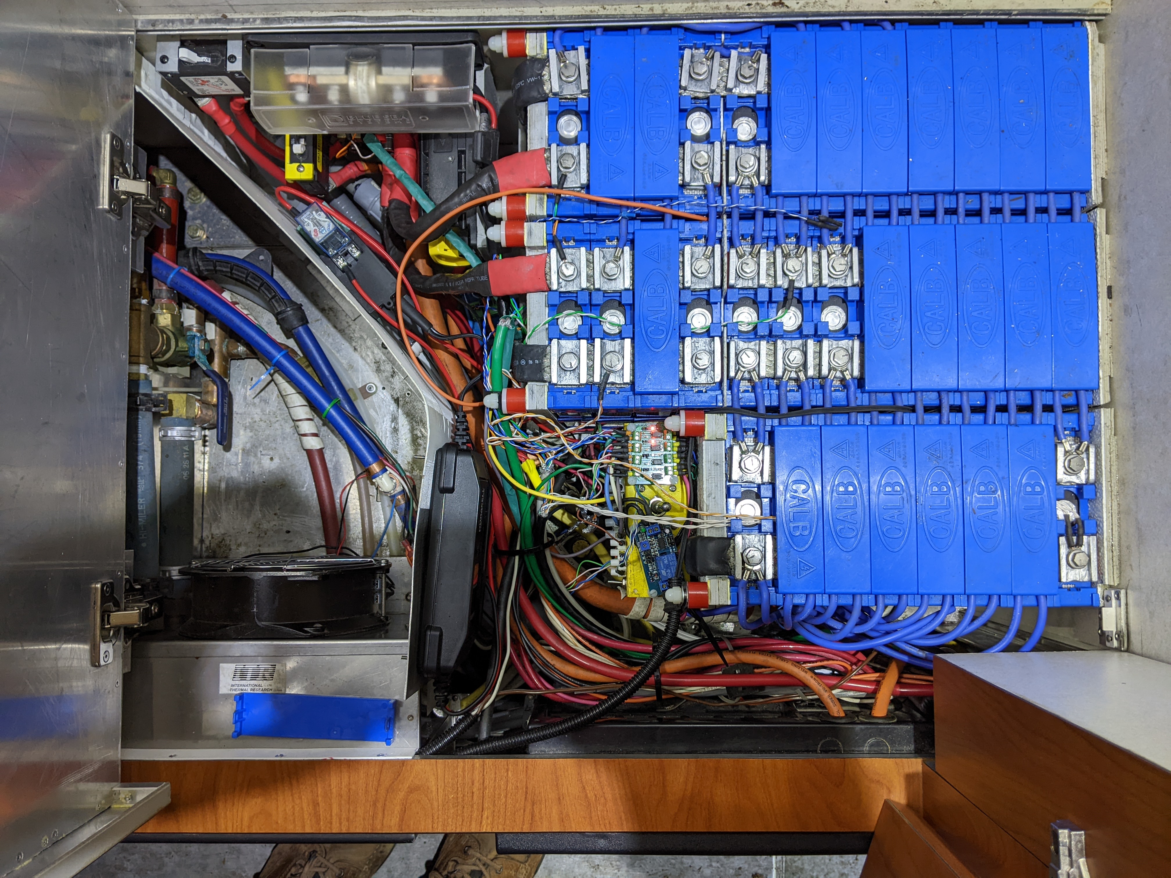
replacement of part of the 4 Channel Optical Coupler with EXIO5 and EXI06, improve battery terminal connection by replacing aluminum pieces with stainless steel Belleville springs, and relocating the SBMS0 to significantly shorten the sensing wires to the maximum length provided.  My existing sensing wires are about 4 Meters long.

Just so it is not a question, I rebooted the SBMS to make sure all parameter and advanced parameter settings were factory except I corrected the external temperature settings.

Test 1: No sun yesterday so I used a Renogy DC to DC charger set at 30 Amps to charge.  Charged from 50% SOC (just rebooted the SBMS0) to about 58% SOC.  At around 3.43 volts (displayed on Monitoring Screen 1, the screen changed and displayed the screen titled “Press Keys to unlock”.  The Keys did not work.  For ease of reference, I will call this the “Keys screen”.  Once in a while, the Keys Screen would turn off and the Monitoring Screen would turn on and then back to the Keys Screen.  Initially, this happened frequently and slowly took more time on each screen.  When screen changes slowed down, I found that the Keys would start to work on the Keys screen just before the Monitoring Screen turned on.  After a while, the hotel lights turned off indicating that I reach Overvoltage Lock.  I turned all charging off.

Test 2:  Sun was available today.  Still at 58% SOC but figured that I was close to the Overvoltage setting.  Charging with sun at about 15 Amps results were approximately the same as yesterday except I never reached Overvoltage Lock and I eventually got to 
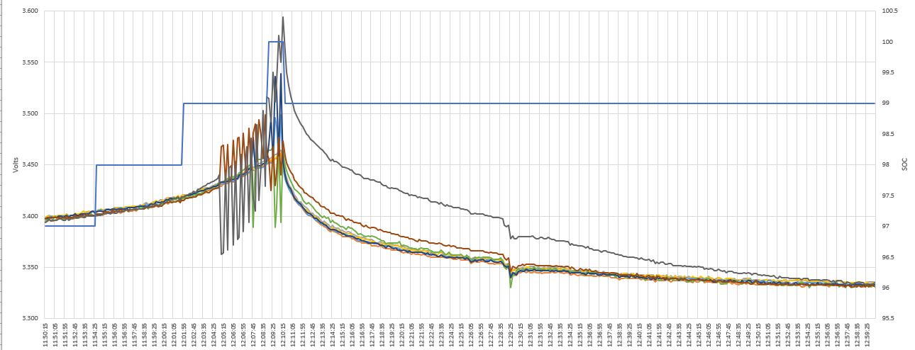
99% SOC.  When the Keys screen was on, I noticed a counter in the upper left corner that I think is a counter for the time a cell reached 3.55 V that counted from 1 to 3 or 4 seconds and the screen would change to the Monitoring Screen for a little while indicating that the 
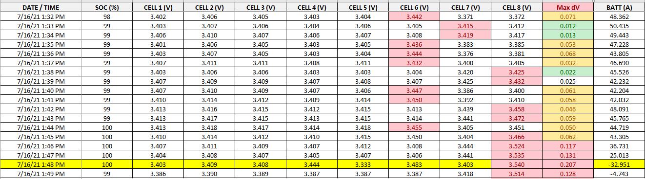
cell dropped below 3.55 V before reaching 6 seconds.  Most cells were at approximately 3.45 V when the Monitoring Screen was on.  Therefore, only at a very low sun charge rate of 15 Amps, have I been able to get to the Overvoltage setting of 3.55 V for 6 seconds without reaching Overvoltage Lock setting of 3.75V.

I am not sure if any of this is normal or if not normal is it related to the installation I did a couple of years ago that has been working fine until now, or if I may have a bad cell.  When I remove the aluminum pieces in the battery connections, I can monitor individual cell voltages for a period of time to see if I have a bad cell.  Is there any other way to determine if there is a bad cell?

Dacian Todea (electrodacus)

unread,
Jun 23, 2023, 12:59:32 PM6/23/23
to electrodacus
It is unlikely there is any bad cell.
Not sure what are you saying when you mention "the screen will change to the Monitoring screen" What screen was before that and screen will not change without your input.
Also the key lock has a timer waiting for you to insert the 3 keys in order up, down and OK in order to unlock the captive keys as shown on screen.
If that key unlock screen appears while you do not press anything it means that you did not properly close the SBMS0 case so the spring contacts do not properly get in contact with the main-board. This is likely because you installed the SBMS0 in to a to thick of a front panel so SBMS0 case could not close fully.

Allen Tindall

unread,
Jun 23, 2023, 2:50:56 PM6/23/23
to electrodacus
Initially, the keys screen works normally and turns on the SBMS0 when you push all three buttons.  Buttons all work normally to allow changing screen.  As a result from charging the day before yesterday with a Renogy DC to DC charger at 30 A where I reached overvoltage lock before reaching overvoltage for 6 seconds the ending SOC was 58%.  Yesterday, charging with Solar at 30 Amps, charging started out at 3.35 volts and charging and balancing appeared to be normal with voltage rising slowly.  Differential was 7 to 10 mv with a 100 mv spike once and awhile.  At about 3.46 Volts, the keys screen came on and I am not sure but the keys on the keys screen did not appear to work.  The screen would change back and forth every few seconds between the keys screen and the Monitoring screen 1.  I think that the keys screen was on only during periods that the voltage of one cell was above overvoltage of 3.55 V but the cell did not stay above overvoltage of 3.55 V long enough to reset the SOC.  After several cycles of this, the SOC went to 99%.  I am not sure if all of this is normal.

One additional problem that I am having and I am not sure if it is related.  When I reset the SBMS0, I pulled the main 400A fuse, switched off all charging and switch off both the main and solar circuit breakers.  After reset, with everything still off, the solar charge shows 0.02 to 0.05 Amps charging current even at night.  I thought that the SBMS0 would recalibrate the solar shunt to zero current during reset.  Once I charge to 99% SOC, if I leave everything off, this current will increase the SOC to 100%.  Any ideas?

Dacian Todea (electrodacus)

unread,
Jun 23, 2023, 5:15:58 PM6/23/23
to electrodacus
The screen/key problems are not related to battery voltage.
You have one of the 4 spring contacts intermittently touching the main board because the case of the SBMS0 is not properly closed with the 4 screws.
You can not have a main fuse. You need to have separate fuses for Loads and for Charge sources after the shunts.
If you disconnect the shunts from the battery you will damage the SBMS0 so please correct the installation before installing a new SBMS0.
Also at power up the shunts need to be connected to battery+ for a proper shunt zero offset calibration.
You will normally see around -0.05A or so that will be the calculated SBMS0 load.

Below you see a simple diagram where battery+ is connected directly to battery shunt with a sort cable no more than 30cm (related to the cable inductance) then PV shunt also directly connected to battery shunt with a short connection and only after that you have fuses or barkers separate for Loads and for chargers.

Screenshot at 2023-06-20 21-41-26.png
Reply all
Reply to author
Forward
0 new messages