Success! SBMS0 control of Push-Button Inverter Power Switch
1,480 views
Skip to first unread message

Ross Freeman
Nov 29, 2020, 7:42:46 AM11/29/20
to electrodacus
Hi all! I'm having a happy moment here. I adopted the SBMS0 in support of an upgrade to lithium on a system I already had installed on a school bus conversion project. I had the "wrong" size panels and the "wrong" type of inverter (one with a push-button power switch).
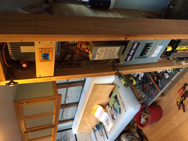
My upgrade was expensive and I didn't want to replace things that weren't broken. So I settled into the fact that I would not be able to turn off the inverter from the SBMS0. I had a new large lithium-iron battery bank and I would maybe add an alert beeper to tell me when to disconnect loads.
But it bugged me that I couldn't turn off the inverter from the BMS0. No toggle switch to solder into.
So I pulled apart my inverter and did some voltage measurements on the power switch and power LED and decided it could be done with a small logic circuit and pulse generator.
Now I'm no electronics guy! Not by a stretch! But I knew I could do this. With help from my electronics buddy over the phone, I managed to put together a circuit that would turn off the inverter based on voltage from the inverter power LED and the output of the SBMS0.
The circuit uses a quad-NAND gate IC and 555 timer circuit. The 555 continuously sends 1 hz pulses and if the SBMS0 and LED inputs are both HI, those pulses feed through to an opto-isolator connected in parallel with the push-button power switch. One pulse turns off the inverter and the LED power signal goes low. The inverter must be manually turned back on.
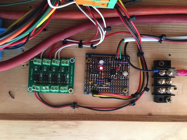
It took me an embarrassing two and a half days to build and debug this circuit. It's not a pretty board but it works! A big plus is that I figured how to connect the circuit board through the "remote power-switch port" on the inverter so no internal modifications were needed on the inverter.
I wish this circuit could be adapted for other inverters but each inverter would have to be considered separately. But the logic would be the same.
Anyway, I'm doing my happy dance!
Ross

Dacian Todea
Nov 29, 2020, 12:58:29 PM11/29/20
to electrodacus
Ross,
Thanks for posting photos of your system. I guess that is a bit of an over complicated remote ON/OFF and not quite guaranteed to work in all conditions but likely the circuit will maybe never need to work as you should not have an empty battery.
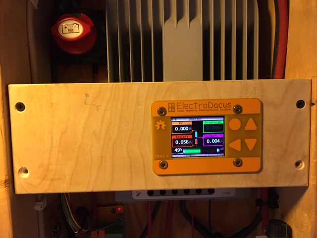
Looking at the SBMS0 monitoring screen it seems all currents are zero even if the DSSR20 seems to be enabled and it seems there is daylight.
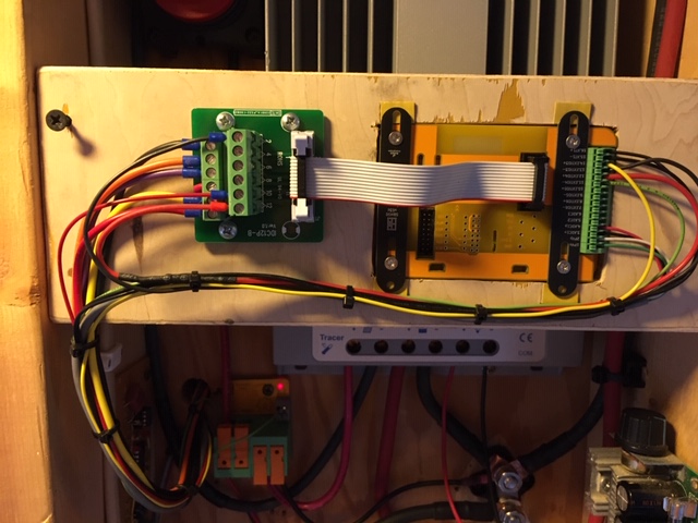
Also I see you use separate wires for current shunt sensing. You should twist those wires so that electromagnetic noise around will not disturb the measurement so just twist the ADC1n/ADC1p and same for the PVn/PVp and you can also do the same for the temperature sensor the EXT IOx are less susceptible so not relevant.
Also I see you use separate wires for current shunt sensing. You should twist those wires so that electromagnetic noise around will not disturb the measurement so just twist the ADC1n/ADC1p and same for the PVn/PVp and you can also do the same for the temperature sensor the EXT IOx are less susceptible so not relevant.

FilterGuy
Nov 29, 2020, 3:00:10 PM11/29/20
to electrodacus
Could you share the schematic of the circuit?
Thanks
Ross Freeman
Nov 30, 2020, 3:20:08 PM11/30/20
to electrodacus
HI FilterGuy,
I modified the circuit to be simpler but I haven't put this together yet... parts are on order. But I'm pretty certain this will work fine with my inverter. I spent some time today using Scheme-it software. Never used it before so be gentle. Hopefully the link will work. Here's the circuit:
<iframe width='500' height='300' frameborder='0' scrolling='no' src='https://www.digikey.com/schemeit/embed/sbms0-inverter-interface-freeman-755b07d4ca8c416087b59c9b0a49b388'></iframe>
Regards!
Ross
FilterGuy
Nov 30, 2020, 5:09:45 PM11/30/20
to electrodacus
Nice!
Ross Freeman
Nov 30, 2020, 7:16:30 PM11/30/20
to electrodacus
While waiting on a few missing parts I breadboarded this circuit and it works great. When I get the new parts in I'll put a new board together with the updates and install it.
Ross
Ross Freeman
Dec 14, 2020, 5:09:49 PM12/14/20
to electrodacus
https://www.digikey.com/schemeit/project/sbms0-inverter-interface-freeman-755b07d4ca8c416087b59c9b0a49b388/Just a final update on the inverter control circuit board...
I finished the board and installed it and it's working great! It only has a few components and would be easy enough to replicate. I also updated the schematic in the link below. The SBMS0 is working GREAT!
Having fun!
Ross
Dacian Todea
Dec 14, 2020, 11:41:13 PM12/14/20
to electrodacus
Thanks for posting the schematic Ross,
I see how it works when you have access to the power LED as feedback.

Oberon Robinson
Feb 6, 2021, 11:56:41 AM2/6/21
to electrodacus
Hi Ross, I'm going to see if I can apply your circuit design to my Giandel PS-4000QAR inverter that also has a momentary power button. I tried to generate a BOM from your schematic but it isn't populated with the components, do you by any chance have a parts list already made up? No worries if not, just trying to save a bit of time. :)
Dacian Todea
Feb 6, 2021, 12:29:59 PM2/6/21
to electrodacus
Oberon,
All parts are noted on the schematic and there is not much there just a 555 times (can get it in any format you prefer) an optoisolator PC817C a transistor 2N3904 the rest is just an LED a bunch of resistors and a few capacitors all with corresponding values in the schematic.
Dacian Todea
Feb 6, 2021, 12:33:20 PM2/6/21
to electrodacus
I think you have a 24V inverter so you need to consider that and may need to make some changes as his was at 12V
Oberon Robinson
Feb 6, 2021, 2:39:33 PM2/6/21
to electrodacus
OK thanks. Yes I still need to measure the internal voltages and adjust accordingly, and check the edge trigger - will this circuit latch on either a positive or negative edge? I have very limited circuit design experience!
Ross Freeman
Feb 7, 2021, 6:18:42 AM2/7/21
to electr...@googlegroups.com
Hi Oberon,
Glad to see someone else benefiting from this. I don't profess to be an electronics person... mechanical designer by trade, but this circuit was pretty simple. For 24v you can probably get by with a 12v 400mw zener diode and 10uf capacitor in parallel as explained in the following link:
Measure your inverter voltage through its push-button circuit and adjust the 4.7k resistor value for the "Power LED" as necessary. All other components can likely stay the same.
There really is no latching in the circuit. It merely imitates the action of an operator pushing and releasing the power button. In my inverter, if I pushed the power switch and did not release it, the power would stay on. Releasing the button triggered the inverter power to turn off. This is the reason for the 555 sending pulses. It will work for either positive or negative edge triggered inverter circuits.
I look forward to hearing your results (with pictures)!
Regards!
Ross
Dacian Todea
Feb 7, 2021, 11:46:57 AM2/7/21
to electrodacus
It is better to use a linear regulator for 12V as battery can be close to 29V in some cases so 29-12V = 17V and it is above the 555 spec (I think that is absolute max 16V).
Oberon Robinson
Feb 8, 2021, 5:52:01 PM2/8/21
to electrodacus
Thanks Rich, I'm a mechanical guy myself so this is a bit of a stretch for me as well, but I'm getting there. Great idea to use the power LED for feedback!
I will have a 24V-12V DC-DC converter in the van, so I can run this circuit off that. Not yet determined what the voltage of my inverter's push-button circuit is, once I have that measured I will see what I need to do to adjust accordingly.
Cheers,
Oberon
Oberon Robinson
Feb 8, 2021, 5:52:37 PM2/8/21
to electrodacus
Sorry, Ross, not Rich!
Ross Freeman
Feb 8, 2021, 10:51:56 PM2/8/21
to electrodacus
I'm rooting for you Oberon. It was fun putting it all together. If your inverter came with a remote switch like mine did, crack it open and take a couple of measurements. Let us know what you find out.
Regards!
Ross
Oberon Robinson
Feb 14, 2021, 4:43:55 PM2/14/21
to electrodacus
I finally got a power supply hooked up to my 24V inverter and measured the voltage at the remote switching circuit. 13V. And mine also works on the button release (trailing edge).
So it looks like I can use this circuit exactly as designed, running off my 24-12V DC converter. The only challenge there is that my DC converter will get switched off at the same time as the inverter!
I'm thinking if I just add a capacitor + resistor across this circuit's power supply, I can keep it powered just long enough to do its thing.
Ross Freeman
Feb 14, 2021, 5:38:35 PM2/14/21
to electrodacus
Soooo... I hear ya on the capacitor. But if it were me and I was gonna build this circuit anyway, I'd throw in the 12v regulator and cut-out the middle man. Just my two cents.
Glad to hear the power circuit is simple and should hook right up! Keep me in the loop!
Regards!
Ross

Tim Rotunda
Mar 29, 2021, 9:19:54 PM3/29/21
to electrodacus
Looks like I am late to the party. I have a 3kw Gaindel and it has that stupid "I'll think about it" type power switch. I can't find the referenced schematic above but I am going to go another route. I can't swing a dead cat around here without hitting a microcontroller, so I am going to use something like an Arduino Nano Every and control the soft switch and monitor the power on an analog port. Super simple and easy to build cause its already built. Just a couple of wires and bob's your uncle.
Oberon Robinson
May 19, 2021, 12:36:37 PM5/19/21
to electrodacus
So I built this circuit, and.... I can't get it to work. I've gone over and over it, and can't find anything wrong. Neither the LED flashes nor the inverter gets switched. The only thing left that I can think might be wrong would be a bad 555 timer, but I lack the diagnostic equipment to check it, and I feel like it would be easier to switch strategies and use a microcontroller like Tim did, than rebuild this circuit if I may or may not be able to get it to work. But I don't know if I'm just missing something simple that I don't have the experience in circuit design to see. Any advice?
Dacian Todea
May 19, 2021, 10:14:09 PM5/19/21
to electrodacus
Oberon,
Maybe a photo of your circuit will help.
Ross Freeman
May 19, 2021, 10:28:24 PM5/19/21
to electrodacus
HI Oberon,
I'm sorry you're having trouble. I live in rural Arkansas and between our bad weather and the usual poor AT&T data service, I can't pull up the darn schematic.
As I recall, the upper portion of the schematic was the timer circuit and as long as it received power and ground, it should operate it's LED separately without connection to anything else, just pulsing the LED on and off in roughly one second intervals. Try disconnecting the signal leading to the 817 opto-coupler and just get the timer working first. Remember, the LED is a diode and can only be connected in one direction.
The circuit is pretty robust and simple but if your not comfortable with electronics it doesn't take long to feel lost. I get it. If I could pull up the schematic I could maybe give you a couple of test points to help you check the circuit but alas... I was barely able to pull up Google Groups to reply to your post. I use my phone for internet hotspot connection. That's my only internet connection at present.
I remember spending time explaining the circuit and how it worked. I tried to be very thorough. It might help you to read through that again.
If you can breadboard the circuit using a wall-wart power supply, I would do that. It allows you to make corrections easily until you are comfortable that everything is working... then solder up a board. It's really easy to make simple mistakes. Myself included.
Let me know what you decide to do. If my internet connection improves I'll get back to you with more.
Best of luck!
Ross
Ross Freeman
May 19, 2021, 10:31:27 PM5/19/21
to electrodacus
Refer to my post in this thread on December 14, 2020. I attached a picture of the board.
Ross
Oberon Robinson
May 19, 2021, 10:56:10 PM5/19/21
to electrodacus
Thanks, disconnecting the 817 and getting the timer circuit working first is a good idea.
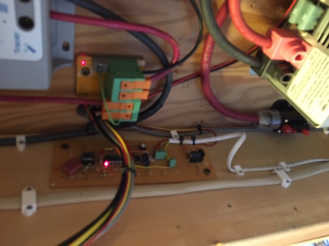
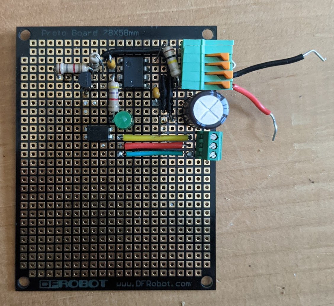
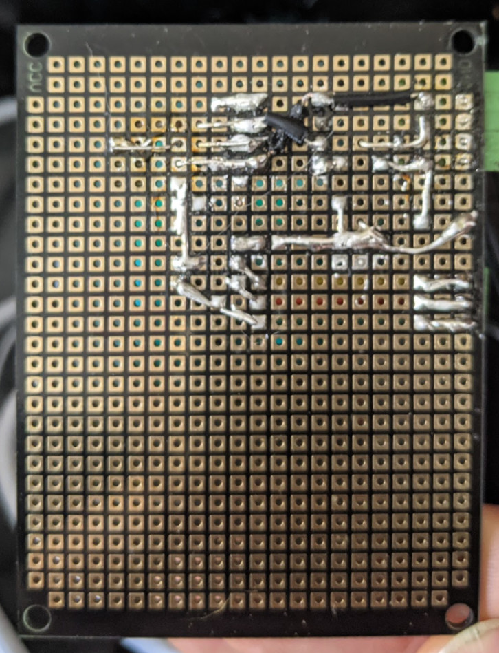
I'm attaching pictures, but I wouldn't expect anyone to try to decipher what I've done, especially since I desoldered and resoldered a lot of the connections multiple times trying to figure out what's wrong. I'm aware that it looks like a complete dog's breakfast. :)
Oberon Robinson
May 19, 2021, 11:00:27 PM5/19/21
to electrodacus
I should mention that I flipped the photo of the back to make it easier to follow.
Also the top 4 orange connectors are EXTIO+, EXTIO-, GND, +24V. The bottom connectors are for the inverter switch.
Dacian Todea
May 20, 2021, 11:58:34 AM5/20/21
to electrodacus
Oberon,
What inverter do you have ? Have you connected the 3 wires correctly to the LED and button ?
Check the GND connection on the 4 wire terminal as that seems to not be connected in the photo based on the height of the orange lever. It may be as simple as that :)
Oberon Robinson
May 20, 2021, 12:15:10 PM5/20/21
to electrodacus
Thanks, I'm sure it is something simple (or a bad 555), but it's not the GND wire. :) I'm going to try Ross's suggestion of isolating the timer circuit and testing that separately, then build it up from there. Or if that doesn't work, I have a spare ESP32 that would do the job instead. :)
I have the Giandel PS-4000QAR. It's 24VDC to 120VAC.
Dacian Todea
May 20, 2021, 12:59:49 PM5/20/21
to electrodacus
In the photo the GND wire is not inserted in the connector. I know those connectors and in the way the connector looks in your photo the black wire is not inserted in to the connector else the orange lever will be at the same level as the other 3
Do you supply 24V directly from battery ? I do not see any voltage regulation or reduction as the 555 (not sure what model you have) will not survive 24V battery. Ross used this at 12V
Have you checked the RJ-11 connections on your inverter as it will likely not be the same for your inverter (there is no standard).
Oberon Robinson
May 20, 2021, 2:34:36 PM5/20/21
to electrodacus
I hear you about the GND connector, but I did have continuity between the wire and the circuit. I've reset the wire in the connector and it looks equal to the others now, but not different results. I've also disconnected the transistor and optocoupler from the timer circuit and it's still not working, I'll try rebuilding it with a new 555 chip, and if that doesn't work then I give up!
So far I've just been testing it at 12V with a bench power supply. The Giandel inverter has 24V on its switch circuit, and I was thinking I could just double the size of the resistor on my board's power in to run it on 24V, but maybe that's naive?

piano jazz
Nov 8, 2021, 5:18:55 PM11/8/21
to electrodacus
hi can you send me where did you buy it to control that power switch
piano jazz
Nov 8, 2021, 5:26:43 PM11/8/21
to electrodacus
Oberon was able to control the power switch
piano jazz
Nov 8, 2021, 5:31:34 PM11/8/21
to electrodacus
Ross freeman
Can you build me that circuit and I'll buy it for you?
piano jazz
Nov 8, 2021, 5:33:49 PM11/8/21
to electrodacus
Ross Freeman
Ross Freeman
Nov 9, 2021, 12:06:17 AM11/9/21
to electrodacus
Hi all,
I admit again that I am an amateur in electronics and do not profess to be anything more. I look back on my schematic and honestly say... "did I really do that?" Ha!
It still works and has turned my inverter off several times when we've had cloudy days for a stretch with current draw on my lithium bank. The Electrodacus BMS is working great!
I would rather not build boards as my focus is finishing my school bus conversion and grandchildren! I'm anxious to get my bus on the road this spring! I'm sure someone with more electronics background than I could take my design and make it work for multiple voltages... then layout a board and have a bunch made. But I doubt there is call for very many to make it worth the effort or cost.
Thanks again and best of luck!
Ross
piano jazz
Nov 21, 2021, 6:30:52 PM11/21/21
to electrodacus
hello you have that simple circuit where can you get it?
On Monday, March 29, 2021 at 9:19:54 PM UTC-4 tra...@gmail.com wrote:

Chris R8
Feb 1, 2022, 8:24:23 PM2/1/22
to electrodacus
Hi Oberon,
Did you get your circuit for the Giandel working?
It looks like the only inverter that suits my needs are the 12V 4000W pure sine inverter from Giandel. But I will only get it if the circuit works.
Oberon Robinson
Feb 1, 2022, 8:49:45 PM2/1/22
to electrodacus
I still haven't got mine working, I admit that I gave up on it after a while, and still need to get back to it. I've been running an inverter without protection since I just turn it on for specific tasks, and keep a close eye on the battery level while it's on. But I intend to get back to this board sometime, it's definitely something that I don't want to do without longer term.
Another option to consider is what Tim R did with a NanoEvery board: https://diysolarforum.com/threads/giandel-inverter-remote-control.20518/#post-242262
Ross Freeman
Feb 3, 2022, 11:08:23 PM2/3/22
to electrodacus
Hi all,
I'm sorry that you've had trouble using my circuit. I did everything I could to keep it simple using only a few components. It's working great for me. My link to the Digikey website was flakey so I've managed to put the circuit explanation and schematic into a pdf (attached). I hope this helps.
I was as careful as I could be in explaining how the circuit works so that others could follow it. I hope others can make a same or similar circuit for their needs.
Best of luck!
Ross
Reply all
Reply to author
Forward
0 new messages