Dual PV heat diverted grid backed-up system diagram review !
571 views
Skip to first unread message

Bjorn Teani
Jul 16, 2021, 7:36:49 AM7/16/21
to electrodacus
Hi all !
Finally i have my complete diagram. I think I bought the SBMS0 over a year ago…. time flies.
The main objective with this system is to heat 3x100L isolated water tanks and use this water to heat my workshop floor.
And to make use of my panels in the summer I thought I add some batteries to make thing interesting and power some stuff (the office part of my workshop).
The heart of the system will be the SBMS0. And the link to the mortal world would be a Multiplus II 24/3000VA. It’s connected to the grid and thanks to the Virtual Switch it is told to ignore the AC in from the grid as long as :
- the power need are under 2,5KW
- (or) the battery pack is above a certain tension level
I’ll try to be very conservative for the battery settings as I hope this system would last long enough to be profitable. As I’m grid connected (0,165€/kWh), if I’m honest, running on batteries can be a waist of money as I calculated that I need it running as it is for at least 12 years to recover my costs. And that’s without factoring in the cost of the solar panels… But I’m already off topic.
The solar panels are SoliTek Standard M.60-B-330 full black monocrystalline 60 cell module
The battery is a 8SP1 3.2v 310Ah Lifepo4.
Here are the part I do not have yet (and I need your input on this) :
- 32A DC Breaker (x12) : TMC 71C 32A
- Battery and PV Shunt : Rideon MKB-300 50mV
- 200A T Fuse : JLLN200.X 125VDC
- 50A Fuse : EATON NON-50
Please feel free to comment on my choices before I hit the buy button.
Bonus questions :
1 - When running on battery, i would be "off grid" for L and N but still tied to the PE of the grid. Is that in some way a security hazard ? I am using differential (30mA) breaker on my "off grid" breaker panel, so I think this would be OK, but I’m still asking.
2 - the Multiplus and the Virtual Switch will be switching the AC in ON i case of a battery voltage below a certain level stopping the drain (it will not be a SBMSO decision…). As I want the grid to kick in seamlessly, I thought the was the best / simplest solution. Correct ?
Finally i have my complete diagram. I think I bought the SBMS0 over a year ago…. time flies.
The main objective with this system is to heat 3x100L isolated water tanks and use this water to heat my workshop floor.
And to make use of my panels in the summer I thought I add some batteries to make thing interesting and power some stuff (the office part of my workshop).
The heart of the system will be the SBMS0. And the link to the mortal world would be a Multiplus II 24/3000VA. It’s connected to the grid and thanks to the Virtual Switch it is told to ignore the AC in from the grid as long as :
- the power need are under 2,5KW
- (or) the battery pack is above a certain tension level
I’ll try to be very conservative for the battery settings as I hope this system would last long enough to be profitable. As I’m grid connected (0,165€/kWh), if I’m honest, running on batteries can be a waist of money as I calculated that I need it running as it is for at least 12 years to recover my costs. And that’s without factoring in the cost of the solar panels… But I’m already off topic.
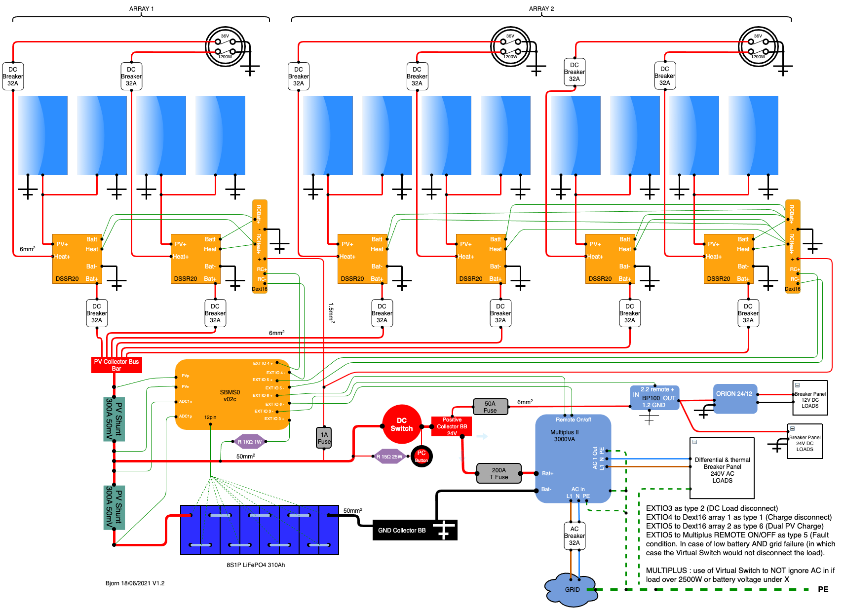
Please review my diagram (inspired from Niels. Thanks Niels !).
The solar panels are SoliTek Standard M.60-B-330 full black monocrystalline 60 cell module
The battery is a 8SP1 3.2v 310Ah Lifepo4.
Here are the part I do not have yet (and I need your input on this) :
- 32A DC Breaker (x12) : TMC 71C 32A
- Battery and PV Shunt : Rideon MKB-300 50mV
- 200A T Fuse : JLLN200.X 125VDC
- 50A Fuse : EATON NON-50
Please feel free to comment on my choices before I hit the buy button.
Bonus questions :
1 - When running on battery, i would be "off grid" for L and N but still tied to the PE of the grid. Is that in some way a security hazard ? I am using differential (30mA) breaker on my "off grid" breaker panel, so I think this would be OK, but I’m still asking.
2 - the Multiplus and the Virtual Switch will be switching the AC in ON i case of a battery voltage below a certain level stopping the drain (it will not be a SBMSO decision…). As I want the grid to kick in seamlessly, I thought the was the best / simplest solution. Correct ?
3 - the Victron BP100 : "Ext IO 3-" goes to "REMOTE +", is that correct ?
Have a great day !
bjorn

Dacian Todea
Jul 16, 2021, 11:58:49 AM7/16/21
to electrodacus
Bjorn,
All looks good except you did not connected the Multiplus to SBMS0 remote ON/OFF controls.
I guess if you disable grid charging then charging will not need to be controlled but if grid goes down then you risk over discharging the battery so at least the inverter ON/OFF control will need to be connected to SBMS0 EXT IOx set as type 2
2 - If you want grid charging then you will need to setup the virtual assistant and control the charging from SBMS0 this will be the document explaining the setup https://www.victronenergy.com/upload/documents/Manual-Connecting-other-lithium-battery-systems-to-Multis-and-Quattros-EN.pdf all will be as shown there except last to settings will use Disable charger.
3 - Yes it will go to H pin on the remote connector. I think they still use H and L notation. You can use the same EXT IO3- to go to Multiplus trough another 10K resistor and a 5V zener diode to GND as multiplus remote ON/OFF the Aux i/O are limited to 5V logic and not isolated.
Bjorn Teani
Jul 16, 2021, 1:48:01 PM7/16/21
to electrodacus
Hey Dacian ! Thanks again for taking the time to answer.
So the DEXT connection are all good ? So is the 300A 50mV shunt choice ? The wire gauge ? ... :-)
An you are right, I haven't thought of the case when the Grid goes off. So I will connect EXT IO 6 to the MP. But I will have to find a way to sense if the grid is still on or not so it turns off the inverter only if the grid isn't there. Otherwise I'll want the inverter to keep on powering from the grid. I'll have to dive deeper in the Multiplus manual. Or maybe I just set the disconnect level on the SMBS lower than the virtual switch AC not-ignore it could do the trick : below a certain battery tension, the MP accepts grid input and if its not there and it drain's further the battery, the it will reach the SMBS disconnect level. Yes, I'm thinking out loud.
I although want to thank Oberon for his great work on the Beginner's Guide. Great work !
To all of you reading this, if you see something that could be done smarter (and I'm sure there is) please tell !
Dacian Todea
Jul 16, 2021, 1:54:25 PM7/16/21
to electrodacus
Bjorn,
I have not noticed the wire thickness noted in the diagram but yes 6mm^2 is a good choice. The 300A 50mV is also sufficient for 3000VA inverter and 24V battery.

Clowny666
Jul 19, 2021, 6:39:12 AM7/19/21
to electrodacus
I'm in the process of designing my system and it's always so useful learning from others great designs. I was wondering about the location of the 200a fuse, maybe I am overthinking but if that fuse blows what happens to the DEXT16's? And, should the Multiplus have a separate fuse, if it shorts it takes the 24v loads with it which are probably critical loads?
Bjorn Teani
Jul 19, 2021, 10:19:03 AM7/19/21
to electrodacus
Good point Clowny666 ! Thanks.
So I moved the 200A Fuse closer to the inverter.
I also added the (direct) connexion between EXTIO6 and Remote On/off. EXT IO 6 will be set as type 5 "Fault condition" and should trigger in the situation where I lost grid and battery gets lower than "Low Voltage Chg" set-point (at witch point the SBMS should have already cut the loads attached to the Orion. In normal situations, when getting to the "‘Low Voltage Chg" set-point the Orion should be cut off and the Multiplus should have stopped ignoring AC in.
At least, this is how I picture it... I could be wrong or they could be other solutions. I do not want to use the "Assistant" functionality as I can't use it at the same time as the Virtual Assistant and I do not have found a way to ignore OR not-ignore AC in with it.
Bjorn Teani
Sep 9, 2021, 2:53:10 AM9/9/21
to electrodacus
Hi !
Just a few question as I'm building up my system (still waiting on the battery).
- Is there any way the SBMS0 could monitor the PV Power going into heat diversion ?
- the two resistance on each heating module are paralleled. And they should stay this way, right ?
- I plug a very small battery pack (6s4p 18650cells) and I tell the SBMS I have 8Ah battery pack (to be very conservative), the SMBSO will automaticaly handle the right charge current ? (For now I have the 4 panels from Array 1 and just 1 panel from array 2 connected).
Dacian Todea
Sep 10, 2021, 1:16:52 PM9/10/21
to electrodacus
I have no option at the moment for monitoring the power and energy going in to heat diversion but I will probably offer a external current shunt that will provide SBMS0 feedback about diversion current and voltage either over I2C or using one of the two ADC's
What sort of panels are those ? You will need to set a current limit in the DMPPT menu but SBMS0 can not limit the current all it can do is check the current on PV array 1 and 2 and select if array 1 or array 2 or both need to be connected while still being under that minimum set limit.
So say you set a 4A limit but you have a 10A panel on one array and a tow 10A panels on array 2 and if there is full sun the best SBMS0 can do is connect the array with a single panel so you will get 10A even of you set a 4A limit.
Why 6s and not 7s ? In any case if you have 60 cell panels likely those are around 300W each so you can not connect such a small battery to that system as even that single panel on small array is much higher current output than those batteries can handle. I will say those sort of cells can handle at most 0.25C to 0.3C and so assuming 2Ah cells you will need a minimum of 30Ah battery so at least 7s15p
Not sure how you define array 1 and 2 but array 1 is controlled by the type 1 and should have 1 panel and the array 2 is controlled by type 6 and ideally should have 2 panels not 4 unless you battery can handle 40A for 1 or 2 seconds.
As a resume you should have at least a 30Ah battery then you can have dual array with 1x 10A panel on array 1 and 2x 10A panels on array 2.
Bjorn Teani
Sep 10, 2021, 2:13:03 PM9/10/21
to electrodacus
The 6s4p that I had laying around is just for testing purposes. And I thought the 18650 could handle 5C (i do not care about longevity).
And I couldn't go lower as 10A for the limit you suggest in DMPPT menu.
I hadn't much of sun the last days so I saw maximum 5A from the two arrays (2x300W + 4x300W). I know that in a sunny day, the small array will already produce around 20A and I was wondering if the SBMS0 would cut both array as even the small one is over the set limit... But according to your answer : no. And I know my battery pack is way undersized but I think the SBMS could "decide" to cut all charge if it can't stay under the set maximum.
I will be looking for your current / power measurement solution on the heating/diverting side, but as you are talking about the "two ADC's", I was wondering if my "old" SBMS0 v.0.2b / 4.0p can follow this evolution as I couldn't find any more ADC's... ?
And I can't seem to distinguish PV1 from PV2 either. Do you confirm that my hardware version is limited in that regard ? Or did I miss something ?
Dacian Todea
Sep 10, 2021, 2:23:45 PM9/10/21
to electrodacus
Is super unlikely any 18650 can handle 5C continues.
There is no lower than 10A limit as it will make no sense since most single panels are already at 10A
The SBMS0 was designed to cut just the large array the small array is the minimum level.
So you will have L1: small array then L2: large array and L3: both small and large. They will only all be off if battery is fully charged.
Yes all versions of SBMS including the older SBMS0 has the ADC's available normally on the WiFi/USB board if you have that option if not you will need to connect to the 16pin connector and add the two divider resistors to access the ADC2 and ADC3
But is more likely that I will want that shunt to be connected over I2C
None of the SBMS0 have anything other than PV1 the dual PV array will not require two separate PV measurements. The SBMS0 will switch the small array on so L1 and if that drops to half the limit say DMPPT limit is set at 10A then if small array only provides 5A it will test the larger array and if that is below 66% of the same 10A limit so below 6.6A then it will connect both the small and the large array. If then sun will get out and current increases it about a second it will disconnect the small array then if that is not enough the large array and leave the small array only as long as that is above 50% of the set limit.
Bjorn Teani
Sep 10, 2021, 4:39:22 PM9/10/21
to electrodacus
Thanks again for the time taking answering me (us !). I really appreciate your logic/design/products... but it does present a challenge to navigate the manual(s) and "discussion group" to find all the answers.
And you're (of course) right. I do not remember where I saw 5C... 1C seems to be the maximum. Well, as I said : "testing purposes" and 2C shouldn't do good, but it will not explode (will it ?). I can't wait to get my 310Ah (...) cells to see your BMS in full action !
Waiting also for that shunt over I2C now ! ;-)
Dacian Todea
Sep 11, 2021, 1:49:34 PM9/11/21
to electrodacus
The problem is that cells have large enough internal resistance so that if you try to push 2C in to them voltage at terminals of the cells will increase above 4 or 4.2V limit so charging will just stop immediately. Thus you will think you have a fully charged battery when that is not the case.
Bjorn Teani
Oct 21, 2021, 3:26:12 AM10/21/21
to electrodacus
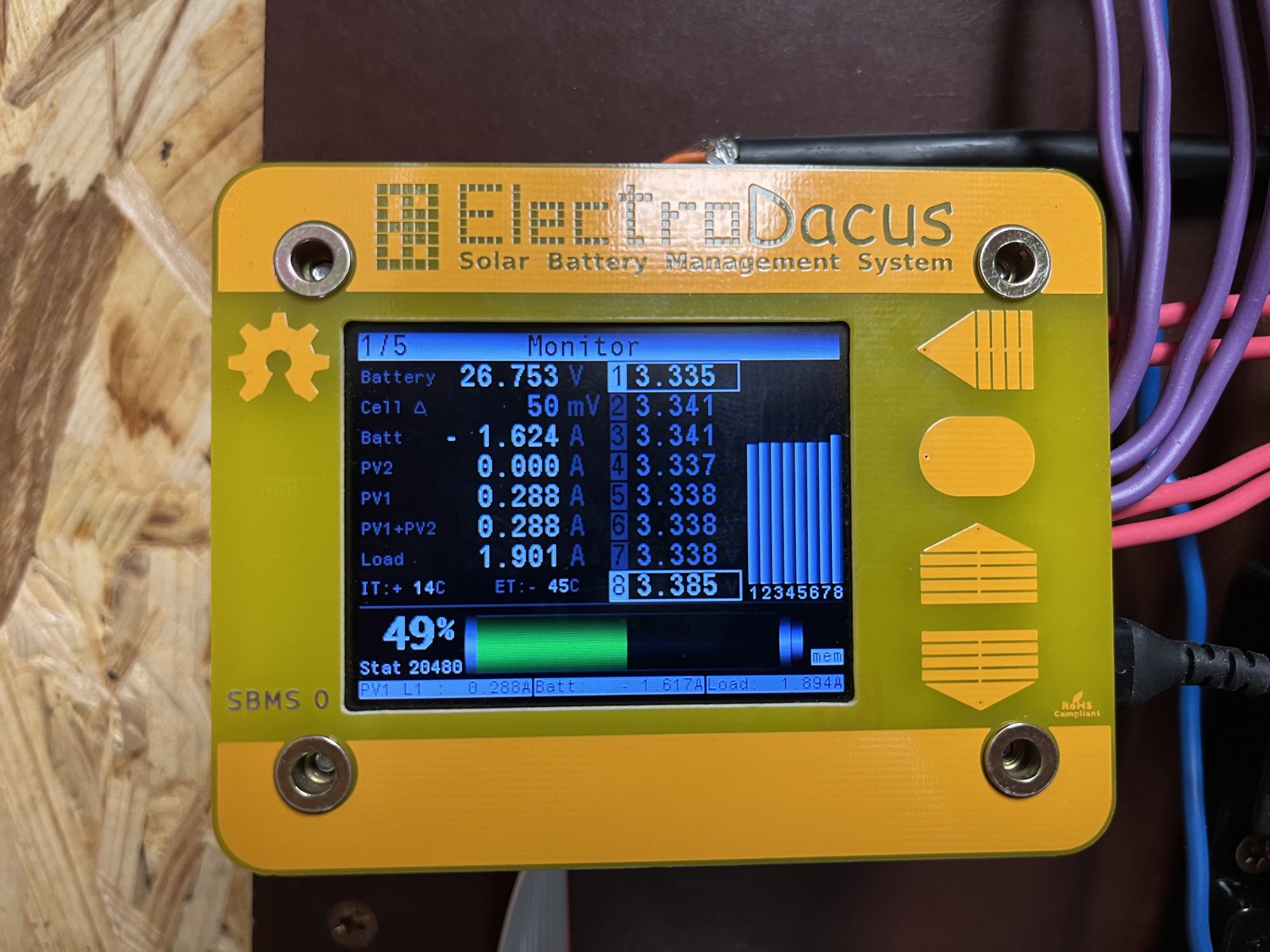
It's alive !
Well without the LOADS part hooked up... And some final adjustment (proprely mounting the SBMS0, protecting the battery...)
And now I'm waiting for some sun.
Quick question : Why do I see LOAD 1.901A when the only thing wired to the LOAD part of the circuit are the DEXTs and DSSRs ?
When I booted up th SBMS I had absolutly no loads (I even disconnected the DEXTs and DSSRs) so I think calibration process went as good as possible. So where do this 1.901A come from ?
Message has been deleted
Bjorn Teani
Oct 21, 2021, 4:38:50 AM10/21/21
to electrodacus
Too bad I can't edit my previous message. I wasn't fully awake so I had to shunt wires wrong and I forgot shunt Resitance correction... But now I have another weird voltage reading on cell 1 : it goes up (way more than the other cells) while charging. But a multimeter reading on the cell doesn't show that... I'll search the forum for the answer (and my mistake, probably).
Dacian Todea
Oct 21, 2021, 2:11:46 PM10/21/21
to electrodacus
After you set the shunt resistance please go to Device settings and push the Save device settings button that way the shunt resistance value will be stored permanently even if you power cycle the SBMS0 they will still be there.
Probably cell balancing is enabled and if cell 2 is balanced then during the cell balancing the cell 1 will show a higher voltage due to cell balancing voltage drop.
A photo showing what happens will be helpful.
Bjorn Teani
Jun 14, 2024, 12:42:15 PM6/14/24
to electrodacus
I'm digging up this old thread as I wanted to share the schematic for the "Solar Carport" addition to my initial setup (Dual PV with diversion).
I will move the already existing 12 panels to be Array 1, and the 20 new panels that will be my carport roof will be my Array 2.
The new panels specs :
STC : Pmax 445W / Voc 40V / Vmp 34V / Isc 14A / Imp 13A.
NOCT : Pmax 336W / Voc 38V / Vmp 32V / Isc 11A / Imp 11A.
I took the NOCT values for my calculations.
Main wiring will from the panels will be 6mm2 (AWG10 ?) and I will need 40m from the carport to the DSSR50.
I will add 8 310Ah cells to add to my existing pack, for a total of 620Ah battery.
I believe these elements will still be appropriate for this install :
- 6mm2 cable from the solar panels,
- 50mm2 cable between the bus bars, the battery and the inverter
- the 620Ah pack handling max power
I think these elements will be enough / OK :
- the 50A DC Breaker after the DSSR50
- the 300A 50mV Shunts
- the 36V / 1200W Heating element
But please correct / advise me better if you think otherwise.
About the shunts : I should switch to 500A, but as the panels will not be in the same configuration (Array 1 being vertical and Array 2 laying flat), they could not reach max output at the same time). Again, please correct me if I'm missing and risking something.
As my setup is growing (and will be even more in the last stage with 32 more panels), I have to be more on point with safety as I'm not understanding everything perfectly. So forgive me my candid question but is it critical to ground the negative side of the battery to the "Protective Earth" of the house ? My understanding was that that this was not critical for safety reason but for interference reasons. (By the way, the chassis of the solar panels are not but will be grounded to PE. Please tell me how wrong I was to be lazy at this thing and risking the electronics)
Bonus question : how would your DMPPT100 fit in this setup ? Should I wait for it before setting up the heating side of my setup ? Because, I will go though the hassle of fitting 5 heating elements at the bottom of recycled water boiler tank and as far I understood the DMPPT100 will act as a switch between different resistors... So what do you think Dacian, should I be patient ? But no pressure on you, of course ;-)
Cheers,
Bjorn
PS : on this schematic, Only array 2 is new. Please check the wiring of the DSSR50 / DEXT16.

Dacian Todea (electrodacus)
Jun 14, 2024, 6:10:25 PM6/14/24
to electrodacus
Bjorn,
The DC breaker on DSSR50 that charges the battery needs to be next to the PV collector buss as it is meant to protect that wire in case the wire is shorted to ground when current will flow from battery to GND.
Also that particular breaker will need to be 60A as 50A is likely not enough to handle 4 panels and it will trip in some situations depending on type and quality of that circuit breaker and ambient temperature where the breaker is installed.
The one on the heating element is fine where it is close to DSSR50 and 50A is fine there.
The DEXT16 is connected correctly.
Bjorn Teani
Jun 17, 2024, 2:44:12 AM6/17/24
to electrodacus
Dacian,
thank you for your answers.
So globally, my whole system as it is makes sense, right ? You do not see any point that is too much out of balance ?
May I insist on the question if I should bridge the GND collector BB to the PE of the house ?
Dacian Todea (electrodacus)
Jun 17, 2024, 11:49:59 AM6/17/24
to electrodacus
Bjorn,
It is hard to say what are the distances between elements as this is just a diagram.
Fuses and breakers should be close to the source as they are designed to mainly protect the cables in case of short circuit or overload.
So same comment I made about the DSSR50 breaker applies to the DSSR20's breakers that need to be close to battery as that is a source with no current limiting unlike the solar PV panels that are current limited and so they will never be able to trip the breakers or damage the wires.
Also you need a fuse after the battery shunt to protect that 50mm^2 cable going to the DC switch assuming that is a long cable and not just a few cm that can not be shorted to anything. You could move the 200A T fuse there.
Assuming PV charging is limited to around 120A the PV shunt of 300A is OK but if you intend to charge both from solar and grid maybe close to 220A possible battery current then 300A shunt may be a bit to hot and in that case you can consider a 500A one. But if you set the Multiplus charge limit to 50A then with the 120A from PV the 300A battery shunt will be OK.
Not sure how that virtual switch on Multiplus is working. But seeing that only EXT IO6 controls the Multiplus it means that maybe you are not using grid charging (it is disabled in multiplus). Since the EXT IO6 only controls the inverter why it is not set as type 2 ?
My understanding of virtual switch from your description is that grid is used as backup for your AC loads. EXT IO6 should be set as type 2
Bjorn Teani
Jun 18, 2024, 5:25:53 AM6/18/24
to electrodacus
Thanks for your answers, Dacian. The 50mm2 cable is half a meter but I will keep your advices in mind as my setup progresses. And I haven't connected IO6 yet as I'm simply using Victron's Virtual Switch to switch to grid when battery voltage is below a certain level (26V). And I'm not charging the batteries using the Multiplus.
When I reach final stage (30kW peak) I plan on being fully autonomous. But at this time, with this solar area, I will probably have to deal with "administrative" complication. If anyone in France already dealt with a "CONSUEL" and Electrodacus equipment, please tell me how it went (as it is not a typical install with official safety branding everywhere).
And if someone has a answer (or a direction where I could find one) about "should bridge the GND collector BB to the PE of the house ?" that would be great.
In the mean time I wish you all a very sunny summer and I go back cutting wood for my solar carport.
See you !
Bjorn Teani
Sep 23, 2024, 1:06:41 PM9/23/24
to electrodacus
Hello Dacian !
So my setup is almost done and the battery charging part is working great. Even on a cloudy day, I top up ma batteries in a few hours in the morning.
Now as Winter is coming, I need to make use of my new solar setup to also heat my floor (with water). Could you help me out choosing the right heating elements.
I already have the 5x DSSR50 dedicated to diversion heating. Pannels are laying flat with 7° tilt angle. 6mm2 wire. I will use diversion heating only during winter time (when the sun is at it's lowest on the horizon, so panel configuration will be the worst). So what heating elements would you choose for each of the 5x DSSR50 ? 48V 3kW (2x1,5kW //) or 48V 2kW (2x1kW //) or even less ?
Heating efficiency is my main concern, in second place would by heating elements longevity...
And considering that I will probably buy your DMPPT100 how would it fit best in my system (and would it impact the choice of the heating elements ?
Dacian Todea (electrodacus)
Sep 23, 2024, 1:36:20 PM9/23/24
to electrodacus
Are this the panels you will be using
STC : Pmax 445W / Voc 40V / Vmp 34V / Isc 14A / Imp 13A
In diagram I see just two panels per DSSR50 so I will consider this.
In this case you want around (34V-voltage drop on wires)/13A *2 =1.3 Ohms or a bit more to allow for the voltage drop on wires.
3000W/48V = 62.5A
48V/62.5A = 0.768 Ohms
Each 1.5kW element will be 0.768 Ohm *2 =1.536 Ohm so you need just half of an element for each two parallel panels.
The 2kW (2*1kW) will have higher resistance and will probably also be fine a bit better in cloudier days but worse in sunny days in average probably worse overall but not by much.
With DMPPT100 you will need 3 heating elements all together to add up to around 0.65Ohms assuming you will be connecting two DSSR50's each with only 2 of those parallel PV panels.
So you can have 2x 1.5kW one connected to each DSSR50 and one full heating element with the two elements connected in series to get around 3Ohms connected to the DMPPT100 output that will get you a total around 0.61Ohm when all connected close enough to 0.65Ohm
Bjorn Teani
Sep 23, 2024, 2:20:16 PM9/23/24
to electrodacus
The panel type is correct, but I use 4 per DSSR50
So I guess I just halve your resistance values ?
Target per DSSR50 : 34V / 13A*4 = 0.65Ohm
If I get this right :
Without DMPPT100 : I need to buy 5x "3000W 48V" (one per DSSR50)
With DMPPT100 : I couldn't decipher what you just wrote ^^
I do not fully understand how the DMPPT100 will work...
Dacian Todea (electrodacus)
Sep 23, 2024, 10:21:34 PM9/23/24
to electrodacus
The DMPPT100 will combine the panels from two DSSR50 in your case 8x 445W panels.
Then it is able to switch ON or OFF 3 separate heating elements the two connected to the two DSSR50 and one connected to the DMPPT100.
This way DMPPT100 can be efficient in a large range of solar conditions.
So you can use one 48V 3000W 0.768Ohm heating element connected to each DSSR50 and a single 1.5kW 48V 1.536Ohm element connected to DMPPT100
Then DMPPT100 can have 5 resistance levels from low to high
1.536 Ohm
0.768Ohm
0.51Ohm (1.536Ohm + one 0.768Ohm)
0.38Ohm (two 0.768Ohm)
0.31Ohm (all 3 heating elements)
Bjorn Teani
Sep 24, 2024, 2:29:29 AM9/24/24
to electrodacus
Great ! Thanks again for taking the time to explain.
Now, when can I buy some DMPPT100 ? ;-)
Bjorn Teani
Oct 6, 2025, 2:20:52 PM10/6/25
to electrodacus
Hi !
So, I finally found the time to weld the heating box for the now 8 heating elements :
- 3x "36V/1200W" on 6x DSSR20 (one for each coil)
- 5x "48vx3000W" on 5x DSSR50 (coils in //)
Now each DSSR50 is connected to 4x panels Vmp 34 V / Imp 13A. So my calculation is 34V / 13A*4 = 0.65Ohm and by using one "48x3000" at 0.768Ohm so I'm "good", right ?
And why are my DSSR50's leds blinking ? I'guess it's happening when the voltage drops, but it is normal behavior ?
Dacian Todea (electrodacus)
Oct 6, 2025, 2:42:59 PM10/6/25
to electrodacus
When voltage under load drops below 7V the DSSR50 will disconnect the load.
Yes 0.768Ohm is good so in full sun at noon you will get around 1500 to 1600W of heating.
But when voltage drops to around 7V the DSSR50 will disconnect as voltage will be to low to be able to self power and in order to protect itself.
Ideally there will be a digital MPPT (maybe I will work on DMPPT100 this winter for may own use and possibly will offer that if there is some demand). Then heating element can be changed to maintain max power point at all times.
So yes it is normal behavior for the led's to blink when there is not enough sun to keep the voltage under load above 7V. So there is a bit of loss there as it need to be above 64W or so in the heating element to be above 7V drop. So it will work just in the range of 1600W peak when full sun at noon down to around 64W then it disconnects so voltage recovers then reconnects again after a delay thus the blinking.
Bjorn Teani
Oct 10, 2025, 8:31:36 AM10/10/25
to electrodacus
Thanks for your answer, Dacian.
So, this switching to "protect itself" is not altering the device over time, right ?
Dacian Todea (electrodacus)
Oct 10, 2025, 11:05:01 AM10/10/25
to electrodacus
This switching has no effect on the device over time.
Bjorn Teani
Oct 16, 2025, 8:40:40 AM10/16/25
to electrodacus
Hello All !
I'm just recently using my 2 PV arrays at it fullest (during the summer, to preserve the batteries, I switched off some of the panels from my newest largest array.
Now that we are soon entering winter season and as valuable light time decreases, I switched all pannels on. And now I noticed a strange behaviour on some cells (6 in green, and 7 in yellow in the graph bellow) : they reach the 3.550V limit way before the others and trigger a charge stop, making the SOC jump from 90 to 99. And this has happened every day for the last week (at least).
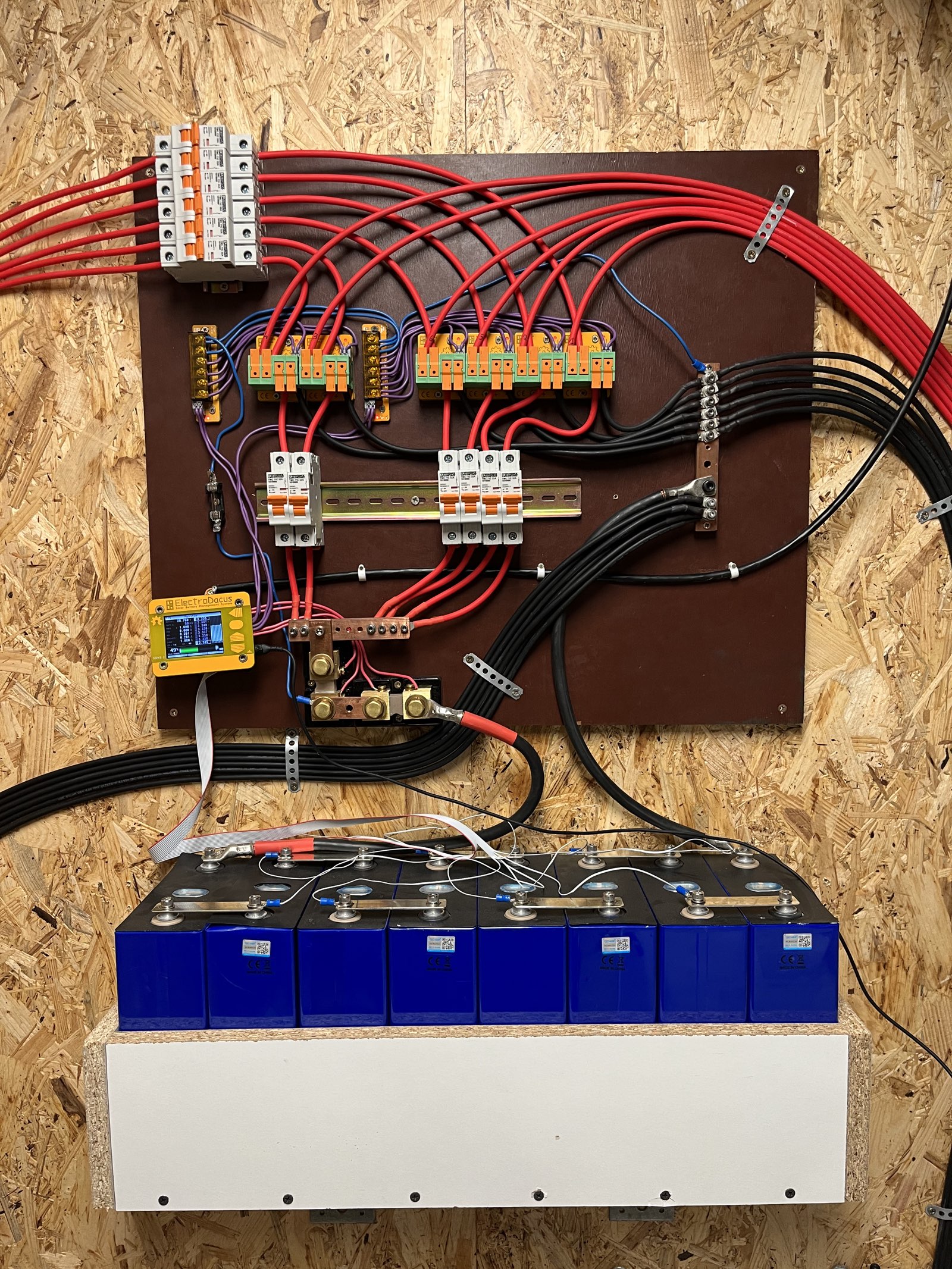
I checked all the battery connection and nothing was loose.
I wonder if the cells are going bad, if I did something wrong or even if I should worry at all !?
And if the SOC jumps from 90 to 100% everytime, it means that the majority of the cells start discharging at 90% SOC, thinkings its at 100% and the next day doing the same (jumping from 90% to 100% on display but actually 80% to 100%), I will lose again 10% of capacity because the 90% on the screen will actually be 70%.... Or am I wrong ? (probably...)
Dacian Todea (electrodacus)
Oct 16, 2025, 2:06:01 PM10/16/25
to electrodacus
I do not see anything wrong with cells.
Based on what you wrote earlier you have just a 310Ah 24V battery. And it seems your charge rate is fairly high close to 0.4C so is possible that error comes from that.
If yesterday it was cloudier the battery was charged at much lower rate all day and so was properly fully charged.
Today the battery could have been set as fully charged at 100% at around 13:00 to 13:00 if the charge current will have been higher closer to 100A and then the jump will have been even higher close to 15% jump in SOC instead of 10% jump.
So your SOC was correct at 90% and it is now incorrect as it was set at 100% due to high charge rate and the normal internal resistance of the cells and voltage drop associated with that at high charge rates.
Actually your battery could have jumped from around 73% to 100% at 12:08 when the magenta cell will have exceeded 3.55V limit.
At that time your PV power was slightly above 3kW (maybe 3.1kW) so 3100W/26.5V = 117A and this is just to much for this cells.
I charge at this type of currents but my battery is 2x larger with 8S2P so about 560Ah
Looking at the magenta cell voltage vs current we can calculate the approximate cell DC resistance internal + connection resistance.
The cell was at around 3.42V when charge current was around 1500W / 26.5V = 57A
And it was close to 3.55V when charge current peaked around 3200W / 26.5V = 120A
120A - 57A = 63A delta
3.55V - 3.42V = 0.13V delta
DC cell resistance about 0.13V / 63A = 2mOhm
Now this 2mOhm as I mentioned is made up from internal cell resistance (DC not AC resistance) and contact resistance + buss bar resistance.
The spec for your cells is that internal impedance is less than 0.5mOhm but that is not the same as internal DC resistance that will usually be around double that depending on design so maybe 1mOhm but to that you also add the contact resistance between the cell terminal and busbar and the busbar resistance. Also the internal impedance and resistance also depend on the cell temperature with colder cells having significantly higher internal impedance.
My recommendation for this type of cells is around 0.2C max charge rate so about half of what you are using.
Bjorn Teani
Oct 16, 2025, 3:42:44 PM10/16/25
to electrodacus
Thank you for the detailed answer, but I also have a 8SP2 configuration (310Ah cells so 620Ah). Since my inital message in 2021 I added 8 cells as I added the 20 panels on my carport.
With the charging limit set at 120A, I'm already within the 0.2 max charge rate... Thus my interrogation !
BUT, could it be that I damaged my cells by having array 2 able to produce too much current for that short period of time when the SBMS switches between array 1 (+2) and array 2 ?
Array 2 consists of 20 panels with :
STC : Pmax 445W / Voc 40V / Vmp 34V / Isc 14A / Imp 13A.
NOCT : Pmax 336W / Voc 38V / Vmp 32V / Isc 11A / Imp 11A
Array 1 consists of 12 panels with :
STC : Pmax 330W / Voc 41,6V / Vmp 33,4V / Isc 10.1A / Imp 9.9A
And, in full sun this summer I've seen the DSSR50 and the DSSR20 switching every two second or so trying to find an array combination that didn't outputed more than the 120A set limit... And I've seen around 4 to almost 5KW as the two array where set on charging for few second, then one array was set to diversion : if it was the small array 1, array 2 was still delivering more than 120A, so array 2 was set to deversion and array 1 to charging. But as array 1 produced around 100A max, array 2 was added... or so I understood.
Could this have damaged some of the cells ?
Dacian Todea (electrodacus)
Oct 16, 2025, 4:19:38 PM10/16/25
to electrodacus
The cells are not damaged but if you have a 8S2P it means that your contact resistance is fairly high maybe there is some oxidation. A photo of the battery will be useful to see if the way you have connected explains the relatively high total resistance.
My setup is fairly similar with 36 x 255W panels in total so a bit over 9kWp array split in two arrays 12 and 24 panels.
You can not damage the cells even if the entire array is connected all the time.
I think you should set the limit to 100A (not 120A) The SBMS0 will keep the array 1 always connected as long as charging is needed no matter how much the array 1 outputs. But this way the array 2 will be connected only when array 1 outputs less than 50A (50% of set limit).
Your array 2 is slightly larger than 2x array 1 but it should be within the tolerances that SBMS0 allows unless you have shadows on one of the arrays but not on the other.
My limit is set at 80A despite the array 1 outputting over 110A in some conditions in winter (especially with snow and cloud reflections).
Your array likely can output 120A and 260A so maybe try disconnecting one or even two panels from the large array as that will fix the 2 second switching between the two arrays.
With your current setting and no shadows the array 2 will be connected when array 1 current drops below 60A and expected current from array 2 will be around 130A (about 3.5kW) but if you seen 4 or 5kW it may mean that you had shadows on one of the PV arrays but not on the other. In any case the 4or 5kW will not damage in any way your battery.
Dacian Todea (electrodacus)
Oct 17, 2025, 12:45:50 AM10/17/25
to electrodacus
I took a few screenshots from my setup so you can compare.
This is from today on my setup with 560Ah battery and slightly over 9kWp array split in two 3kWp and 6kWp
The cursor is set at 13:48:15 when
Just small array was connected and outputting
PV = 1370.6W
Load = 1395.2W
Battery = 24.6W (so less than 1A helping to power the load that required just slightly more than was coming from PV).
All cells very close to 3.35V with a delta of 12mV

Now if we look at the cell voltage over time with 1 second resolution we can see the voltage fluctuation due to cell balancing.
The average power for one minute average at 13:45 from PV was 2163.2W but since there was also a load for half that period the average power going in to battery was 1337.6W
Maybe cell 8 is the best to look at since it is not affected by cell balancing and seems to be at 3.36V max when battery charge current was around 1700W/ 26.78V =63.5A and when discharge current was about 1A cell voltage was 3.341V
So 3.36 - 3.341 = 0.019V drop at 63.5A thus 0.019V / 63.5A = 0.3mOhm (surprisingly low).
Likely when I calculated for your setup I did not had enough info. Like the most important was the actual battery current (I assumed you had no load but most likely that is not true). Also your log rate seems to be higher than 1 second and it will be hard to see the effect of cell balancing.

Here is the SOC for my setup working perfectly fine.
It was lowest 87% in the morning around 8:00
And got to 100% with no jump at 12:08
Then it charged again 4 more times but with SOC limit set at 95%

And here is a last screenshot showing that this app was logging continuously for a bit more than 6 months (186 days). I'm fairly certain it can run for years with no issues (no need to reset the mini computer).

Reply all
Reply to author
Forward
0 new messages