Sailboat: Please critique my configuration and if anyone can help with the questions?
141 views
Skip to first unread message

alex sfakianos
Jul 13, 2021, 6:51:30 PM7/13/21
to electrodacus
Initially sent this to electr...@gmail.com by mistake. I thought I was sending it to the forum...
Greetings and TIA for any help and guidance you can offer. Having got my SBMS0 a few months ago, problems with making and plating the buss bars delayed me and I am just now getting ready to set it all up. I am new at this, though have some basic knowledge, from camper vans, house wiring, college many years ago and more recent reading. This is on a 38 foot wood/glass catamaran. This is a distributed system with a main feed from the batteries to each hull and the cockpit, with individual fuse blocks for each cabin. I think I have a reasonable grasp of the required layout beyond the battery for the shunts, fuses etc.
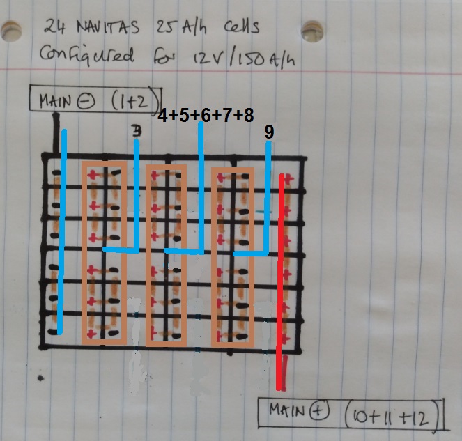
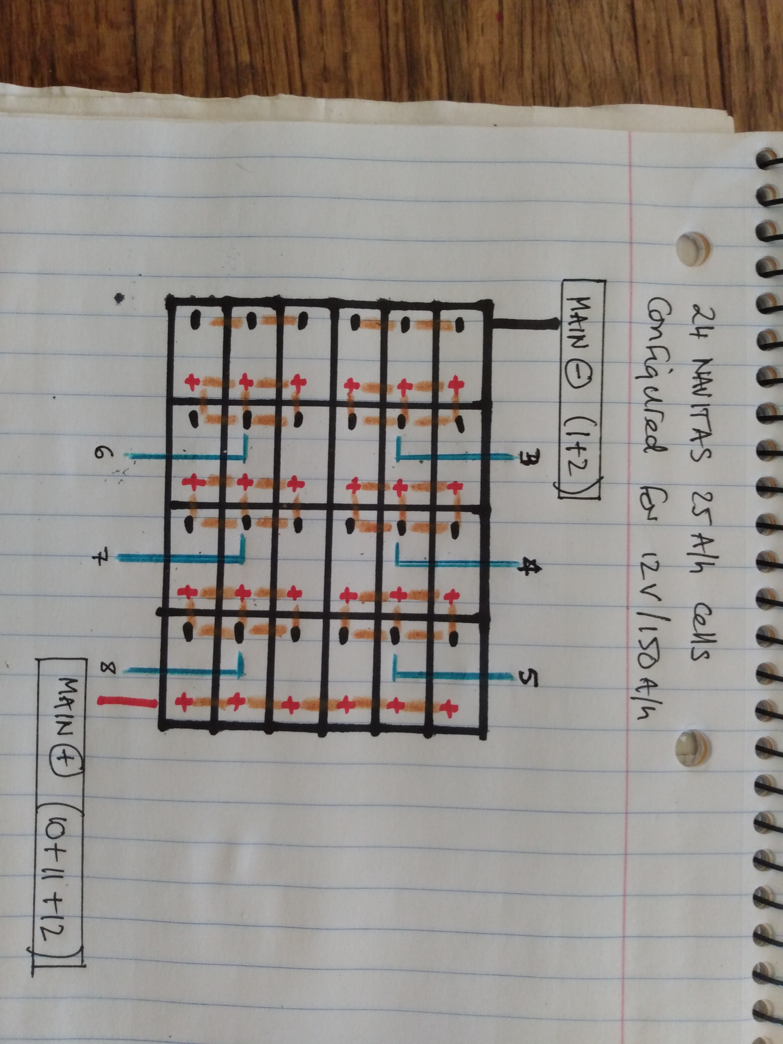
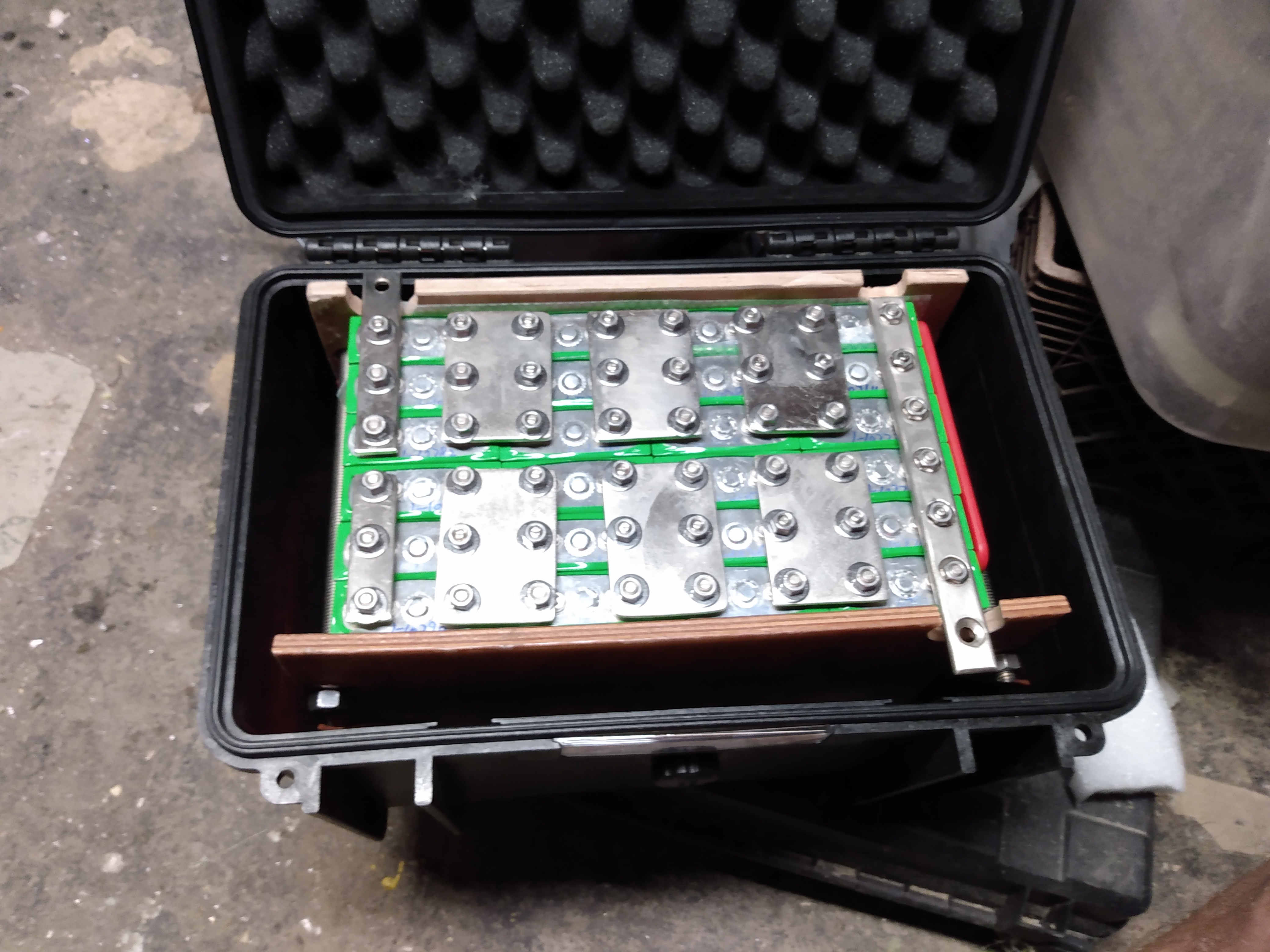
The batteries I am assembling are made up of two 150A/h packs for the house bank and a smaller 75A/h pack for starting the two outboards. Each of the house packs is built with 24 Navitas 25A/h cells, configured as shown in the drawing below. 3P8S configuration? Below that is a photo of the actual pack as assembled. The starting battery will be charged by the alternators, managed with a Victron SBP. I will have provision for charging the starter battery from the house system for emergency use.
My original layout had the two groups of 12 cells in opposite directions but I believe it’s better to have the main connections at opposite ends of the pack (?). Because the Navitas posts are too short for a battery lug with the 1/8” buss bars, I made the end two longer with a bolt hole for the battery cable lugs. Not sure how to address this if the extended buss bars won't work. I can make any cables I need but the lug thickness required won't allow for more than a single connection on the Navitas posts.
First, does this configuration look ok? If so, in the top drawing I have shown in blue where I think the leads for the SBMS0 should be attached. Are these correct and if not, what am I missing?
Then there is an additional problem of having two identical house batteries. This is for for keeping the packs a manageable size and weight as well as for redundancy. Is there a way to connect the SBMS0 to both packs or will I need a separate SBMS0 for each pack? Although this would mean extra expense and complexity I will do that if need be.
(And yes, after putting these packs together I realize that I would have been much better off with a small number of bigger cells but this is what I bought so need to make it work).
This will be a 12V DC system only. The only charging source will be 900 watts of PV. With my calculations of the daily loads this will be plenty for energy independence and I am not going to install a shore power system or a generator. The outboards could be used for charging in an emergency (12A each) but I do not plan on depending on them for charging. I have a Victron 70/15 MPPT for each of the 220W panels because there will be variable shading on the four panels. The MPPT’s will be controlled by the SBMS0 with VE direct non-inverting cables. So can I join the four VE Direct cables at the SBMS0 end so they would be turned on and off as if they were a single unit? If not, how do I accomplish control of the four SCC's?
Whew. Building this boat has been a long haul. I am very close to getting it all done and ready for launching. Having scrimped, scrounged, bargained and struggled over the years to build it with a limited budget, I am now impatient to get it done and within reason will buy any additional items I may need to make this system safe and effective. I will probably have other problems come up as I finish this, but for now I think that’s it.
Thanks.

Plamen
Jul 14, 2021, 2:15:33 AM7/14/21
to electrodacus
Hi Alex, Read this first https://groups.google.com/g/electrodacus/c/BlOJQKmFZ0E
You should decide first either 2 battery packs, 2 SBMS0 and 2 inverters or one battery, one SBMS and one inverter.
Right now your battery is 3P8S but that is 24V. I can't see the cells polarity. Maybe it's 12V but then the main negative busbar must be like the positive all 6 cells together. And for 12V it will be 6P4S.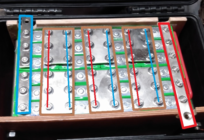
That's for 2 battery packs, 2 SBMS0 and 2 inverters.
That's for 2 battery packs, 2 SBMS0 and 2 inverters.
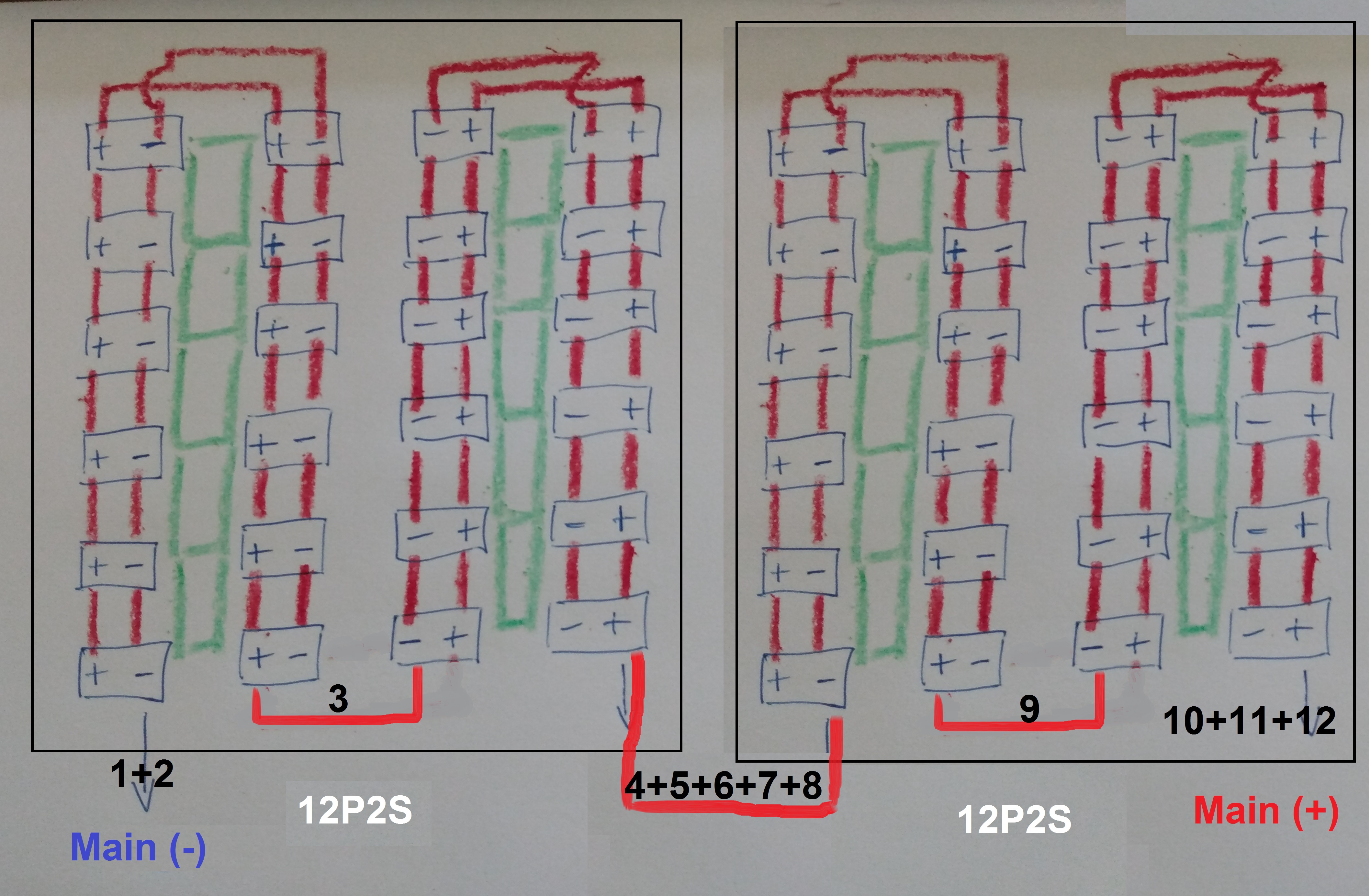
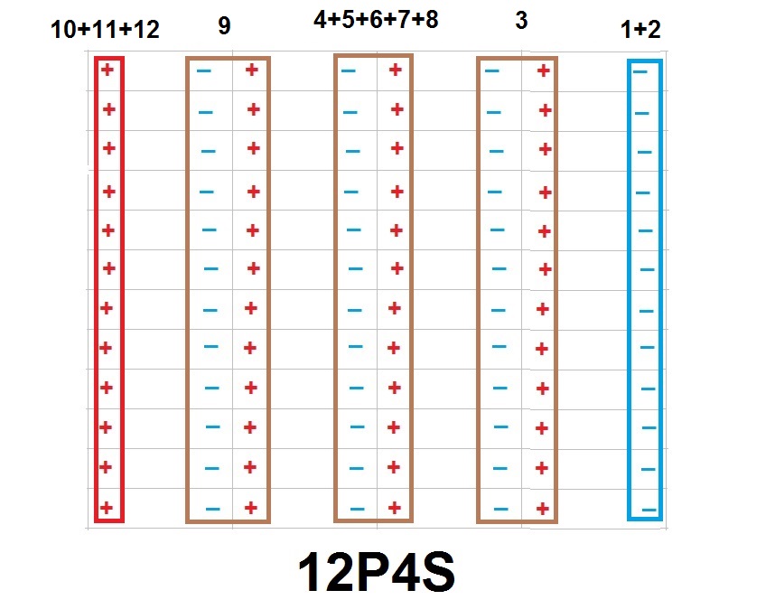
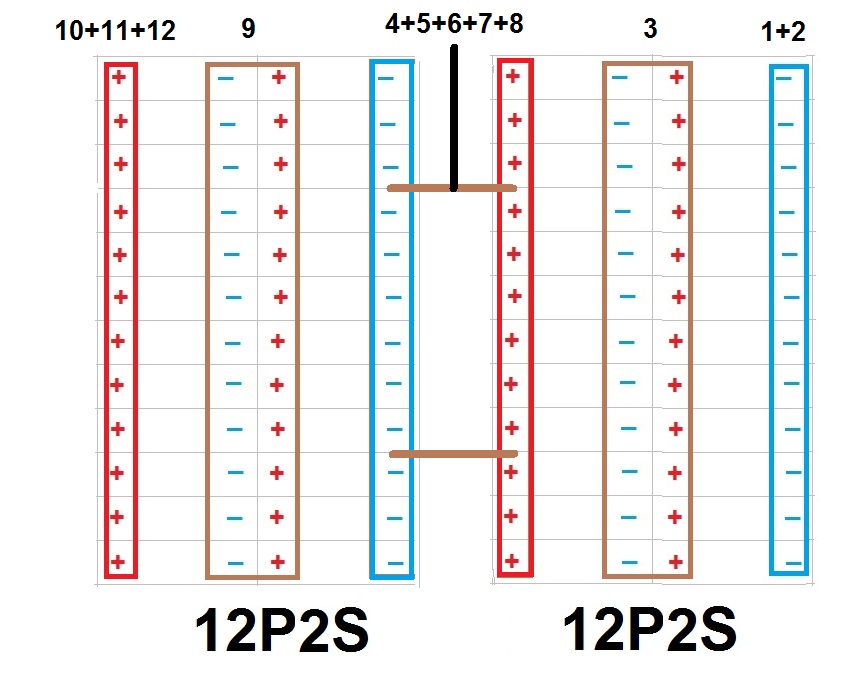
And for one battery you need to make it 12P4S. To be manageable you can split it in two 12P2S with very short cables between. Just the two boxes next to each other It's that you can't parallel packs, just cells.
Also those bars not allow any movement of the cells so not the best option.
Plamen
Jul 14, 2021, 2:18:40 AM7/14/21
to electrodacus
Forgotten to add that not only the main negative but all between cells bars must connect all 6 cells.

Ian Sfakianos
Jul 14, 2021, 11:41:15 AM7/14/21
to electrodacus
Sorry about the change in name, Google has somehow got my sons account mixed up with mine. It''s still me...
Thank you for the reply Plamen. I am beginning to feel I have not given myself enough time to figure all these layers of complexity out but am reading and trying to absorb as much as I can.
I did post a diagram of my battery configuration along with the photo, that should help show the polarity. I based it on a smaller pack layout from Will Prowse site and people on that forum seemed to think it would work. As it is it gives me 12 volts. But it looks like it would require 2 x BMS, adding a whole additional level of complexity.
I will read through the thread you sent me, thank you. I read far enough for a detailed explanation of why their experience was that 2 x BMS is not advisable. So back to a single SBMS and I will have to think about the options you suggested for the cells I have, so I can configure them in two reasonable sized packs that will allow me to use a single SBMS0. Two 6V packs in 12P2S, joined with short cable to make a 12P4S pack sounds ok.
I have not read of any issues with using rigid bus bars for a boat though I agree they will not allow for individual cell movement. Are you saying I should use cable? That was my initial thought but the number of individual cables would be crazy with my small cells! Perhaps I should try to sell these Navitas cells and get myself larger ones for a much simpler set up...
Plamen
Jul 14, 2021, 3:14:24 PM7/14/21
to electrodacus
Alex (it's your son probably but i can't see your whole email), i've never heard of someone that broke cell pole with those but if you add vibrations and fact that will be used on a boat. I never been alone in the middle of the ocean but for sure don't wanna be there with no power. If you can afford to buy bigger cells all will be alot easier but probably that's not the case. It will take more time but you can use those too. 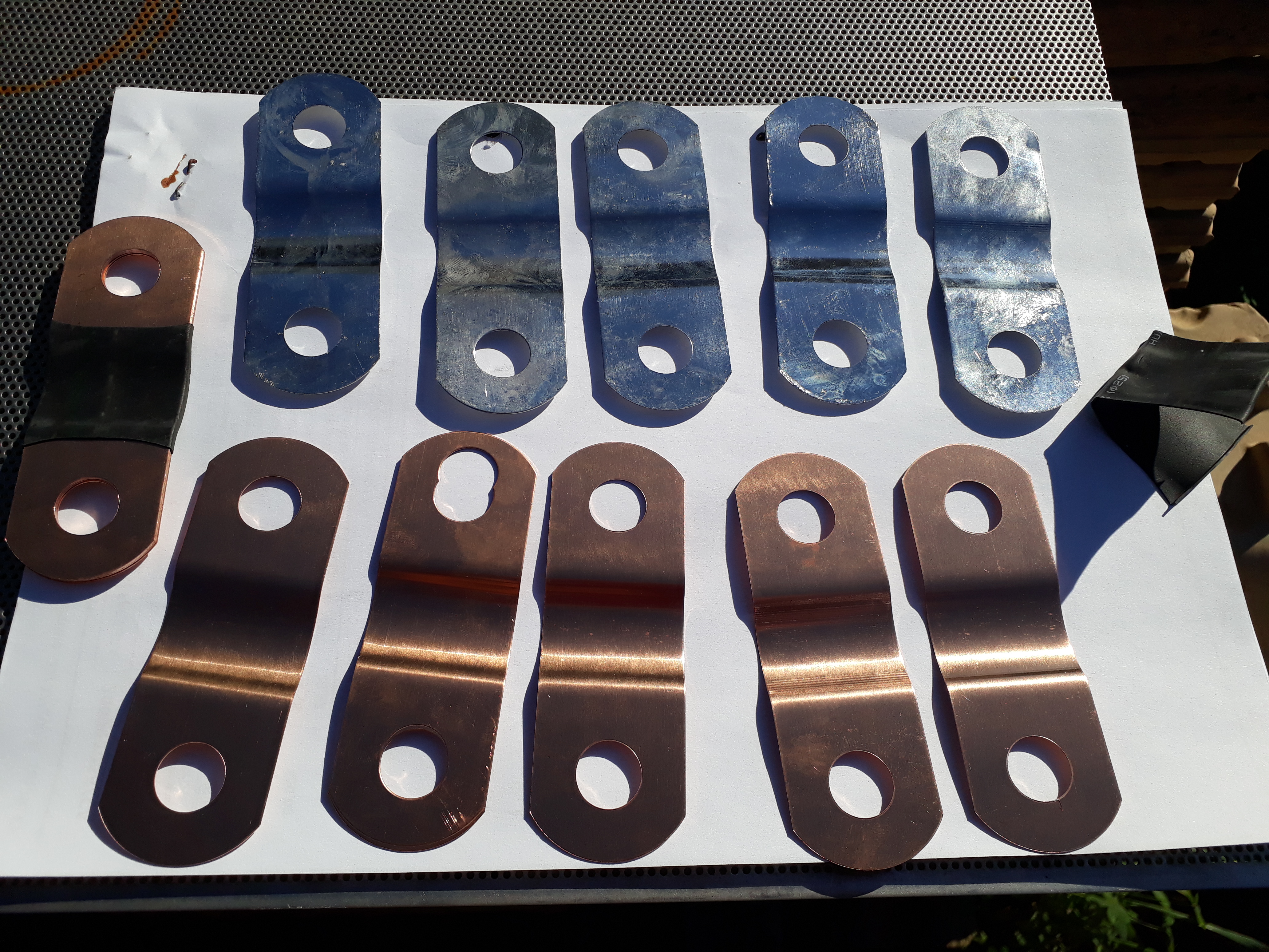
I've received my Winston cells with those busbars. Had to tinn them. You can see thay are made from five plates. Can't remember but each one is probably 1mm or less thick.
In the previous post picture. The blue rectangular (main negative) should be a whole busbar as the red rectangular (main positive). Then those brown rectangulars should be one busbar too ( two of yours). Blue and red lines represent each cell polarity.
Plamen
Jul 14, 2021, 3:48:25 PM7/14/21
to electrodacus
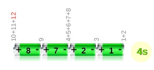
That's for 6P4S. If you split in two 12P2S then 4+5+6+7+8 will be on that short cable that connects both.
Ian Sfakianos
Jul 14, 2021, 6:21:32 PM7/14/21
to electrodacus
Thank you Dacian and Plamen, I did get the emails. I really do appreciate the help. I can change the existing battery configuration to connect all the negatives. That helps. But apparently I didn't make this clear, my plan was to have two of these packs (48 individual Navitas cells) in parallel for a 12V 300A/H overall capacity. I now understand that I cannot use a single SBMS0 for managing two of the packs with my previously posted and now corrected (thank you) configuration. And from the link Plamen posted it sounds like trying to manage two BMS' is not worth the additional complexity. So back to the drawing board...
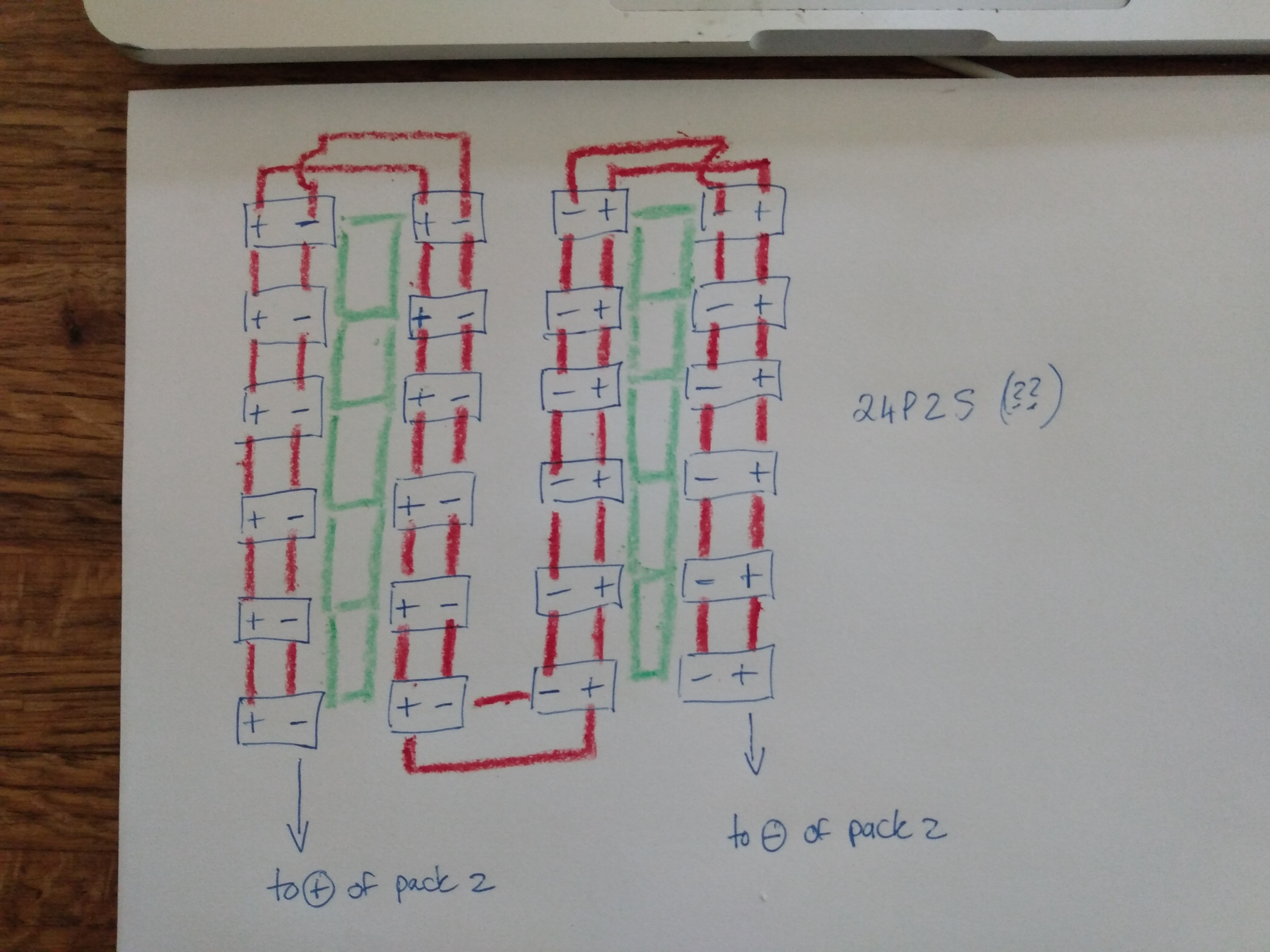
If my thinking on the 24P2S layout is correct, picture below, then I would only have to crimp and seal around 200 terminals. That's a lot, but probably easier than making and nickel plating a whole new set of buss bars. I couldn't find any off the shelf that fit so made my own and then had to go down the rabbit hole of plating, an issue in itself and it took quite a while to sort out to get good, consistent results.
Is there a configuration that allows me to build two packs of 24 individual cells and use one SBMS0 for management? I was thinking that perhaps two 24P2S linked in series with heavy cable. Like the 12P2S you suggested Plamen, just twice the number of cells . Putting the two together in series making a 24P4S pack but what would the SBMS0 sensing wire layout be? I could of course make the 48 cells into a single large pack but have multiple issues with my back and have to be very careful about lifting. I try to plan and design to avoid it as much as possible. Even the 24 cells with compression system, buss bars and box weigh quite a bit.
And Plamen, thank you for the pictures and information on your buss bars. It's another area where I haven't been able to get things entirely clear. I used an online ampacity table for deriving my buss bar dimensions but I had noticed that they are significantly heavier than the bars provided by the battery manufacturers. Your photos confirm that and I may have to source some lighter material. If yours are 1mm thick and perhaps 25mm wide that's about 1/32" thick (I'm in the US where measuring things has not progressed beyond the Stone Age) so rated at perhaps 50-75A? The thinnest bus bar I can reference is twice that thickness and is rated for around 150.
Plamen
Jul 14, 2021, 8:52:30 PM7/14/21
to electrodacus
If it's not the space but the weight the reason you want to have two packs may i ask why you gonna ever move the battery? You build it cell by cell, secure in place and forget.
So you have 48 cells, For 12 volt battery it means 12P4S. The last picture is not correct. That's makes me think that you should be very careful when connecting the cells together.
I've got my busbars with the cells (400Ah) so don't know how to calculate them. For sure are a lot tiner then yours. One more thing, on the pic. that's one busbar made of 5 of those plates so to be flexable.
I've got my busbars with the cells (400Ah) so don't know how to calculate them. For sure are a lot tiner then yours. One more thing, on the pic. that's one busbar made of 5 of those plates so to be flexable.

Dacian Todea
Jul 15, 2021, 11:48:26 AM7/15/21
to electrodacus
There is nothing for me to add Plamen is absolutely correct. Thanks Plamen.
Plamen
Jul 15, 2021, 2:25:57 PM7/15/21
to electrodacus
Thanks to You, glad i can help!
Ian Sfakianos
Jul 15, 2021, 11:51:09 PM7/15/21
to electrodacus
Thank you to you both. I think I am slowly getting the details of this. Could not have done it without you. It does look like the 12P x 4 packs may make the most sense, unless someone wants to buy 60 Navitas 25 A/H cells so I can get 4 cells of high capacity? I'm adding the additional details you sent me Plamen, as you say someone else may find them useful.
"Yes i've sent you two pics. one whole pack and two pack. the difference just that double golden wire.
Dacian have said it many times that number of paralleled cells is not different from a single hi capacity cell.
that's inside a Winston cell like mine. You can see like maybe 20 of those prismatic pouch cells connected to one side of the terminal (with two screws) and another 20 on the other.
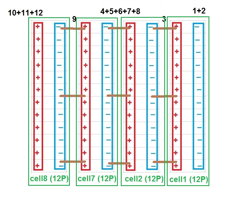
Why don't you make 4 packs of 12 cells. Compress them together and that will be your 300Ah cell. Easy to carry and then connect those 4 'cells' in series to make your battery.
Connect those 12 cells with wire and ring terminals together to make your single cell. Then connect in series i say in 3 points (ends and center) with thicker cable.
Cell 1, 2, 7 and 8 that's how they show on your SBMS screen.
I've received this on my email. If it's by mistake you can post it in the forum. Someone else may find it useful."
Reply all
Reply to author
Forward
0 new messages