Controlling Victron Components, 24 V Setup Check - Input appreciated!
706 views
Skip to first unread message

Nils
May 5, 2021, 10:15:59 AM5/5/21
to electrodacus
Hello there,
first of all thank you and hands down for this great product and more than helpful community board. I was able to find out a lot of information by reading through many of the topics.
As my built has begun to take some shape, I would like to address some questions I was not able to answer by reading the docs / threads. (Not meaning, that it is not explained already, only that I can't wrap my head around all the single aspects.)
I am planning a 24 V setup for our van. Battery will be 8S 200 Ah Winston cells. The SBMS0 will be utilised as the primary (and only) BMS taking care of cut off and balancing.
I am planning to connect the following devices:
- Victron MultiPlus 3000 (24 V) for AC inverting and charging
- Victron Orion TR Smart 12/24-15 DC-DC Booster for alternator charging (only as an backup option)
- Victron Orion-Tr 24/12-20 DC-DC Step Down for running 12 V loads
- Victron BP-100 (or maybe even only BP-65) for cutting of 24 V loads
- DSSR20 for taking care of solar input (400 to 500 Wp)
As I understand, the SBMS0 should be able to control (load / charge cut off) all theses devices for safe operation, correct?
Can the EXT03 / EXT04 simply be split and wired to multiple down stream Victron devices? Or do I need a special circuit to connect all of theses to the BMS at once and make the SBMS0 shut them down all at once when reaching the defined limits?
Also I noticed that only the DSSR20 with diversion seems to be available at the moment (which I don't mind, I like the option to upgrade). But: Am I correctly assuming, that I do not have to use the diversion? Meaning it will also work like a normal non diverting DSSR20, if I want it to?
I was planning on getting the DEXT16 as well for easier handling of the DSSR20. The docs show a 10 kOhm resitor, when connecting w/o DEXT16. Is it safe to assume that this resistor also is integrated in the DEXT16 layout and no separate resistor will be required?
A separate question emerged as I was trying to define which DC-DC converted to chose. Do I need the isolated version or will the non-isolated version for the alternator charging work as well? (I don't see why the circuits would need separation?)
Thank you in advance for sharing your knowledge. I will try to share some details of my built as it goes along to help other new users - as time allows.
Best regards from Bavaria and stay safe,
Nils

Dacian Todea
May 5, 2021, 5:13:34 PM5/5/21
to electrodacus
Hi Nils,
You will need external optoisolators for each device to control with EXT IO3 and IO4 as each of those Victron devices has different voltage standards on remote so they can not be directly paralleled.
Like the Multiplus has 5V logic on the Aux inputs while the BP65/BP100 and the Orion have remote ON/OFF working at battery voltage level so 24V
Yes I only have the DSSR20 with diversion as the one without diversion is out of stock and I can not produce more but the one with diversion can work the exact same way you do not need to use the diversion. There will be a DSSR50 without diversion but that will take a few months to become available.
The resistor is not required if you will be using the DEXT16 tho is a bit of overkill to get the DEXT16 compared to just a resistor.
You can use either the isolated or non isolated version assuming price is better for non isolated then you can get that.
Nils
May 6, 2021, 12:19:24 AM5/6/21
to electrodacus
Hi Dacian,
thank you very much for your valuable input. Highly appreciated! This clarifies a lot of things for me.
Regarding the opto isolator: Is there a ready to use circuit available that only would need to maybe solder some connectors und connect the wires you or some one else can recommend? If I understand the function of the opto isolator correctly, this circuit will need some dedicated voltage supply?
I think I will stick with the DSSR20 with diversion in the case. Just to clear things up: When using the DSSR20 with diversion, but not actually using the diversion feature, the DSSR20 w/ can be connected like a DSSR20 w/o diversion - Meaning no inverting circuit required, only a 10k resistor? In this case I understand your point why a single resistor might be the better solution instead of utilising the DEXT16.
Thanks!
Nils
Nils
May 7, 2021, 8:41:12 AM5/7/21
to electrodacus
Hi Dacian,
I am not sure if you intentionally answered me via email instead of the forum or just by accident. Any way, I will follow up on the informational and picture you provide (thank you so much!).
I was doodling around to figure out the correct way of connecting the circuit and once again stumble on the question regarding isolated / non-isolated DC-DC converters. As stated above I am planning to use two different converters:
- Victron Orion TR Smart 12/24-15 DC-DC Booster for alternator charging (only as an backup option)
- Victron Orion-Tr 24/12-20 DC-DC Step Down for running 12 V loads
I guess the second one (step down from 24 to 12 V) will not need any isolation. But how about the charging booster that will connect to the vehicle 12 V grid on the input side? How will this affect the LH pins controlled by the opto isolator? Will the control voltage still be 24 V level (output side of convert) or 12 V level (input side). Maybe in this case the isolated version is the better option? The more probable answer: I am thinking too much and non isolated will work just as well. :)
Thanks again.
Have a great weekend,
Nils
Dacian Todea
May 7, 2021, 1:03:15 PM5/7/21
to electrodacus
Nils,
It was by mistake that I replayed through email. I still get much more emails than questions on forum and the only difference is a small green label saying that is from forum.
I'm not sure what the control voltage will be but all those Orion's should be capable of handling 24V and they will enable even with as low as 3V so it they will work. There is no voltage on the H pin just on th L pin so if you parallel the H pin you provide a positive voltage and as long as it is above 4 or 5V the Orion will enable. The non isolated version have GND (battery negative) common for the 12V and 24V battery so the H pin can be supplied from any battery it will still be a positive voltage in relation to GND (battery-).
And if anyone is interested this was the replay that was not posted on forum.
"
Yes the DSSR20 with diversion can be used the exact same way as the one without diversion if diversion functionality is not needed.
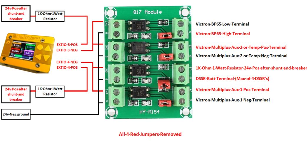
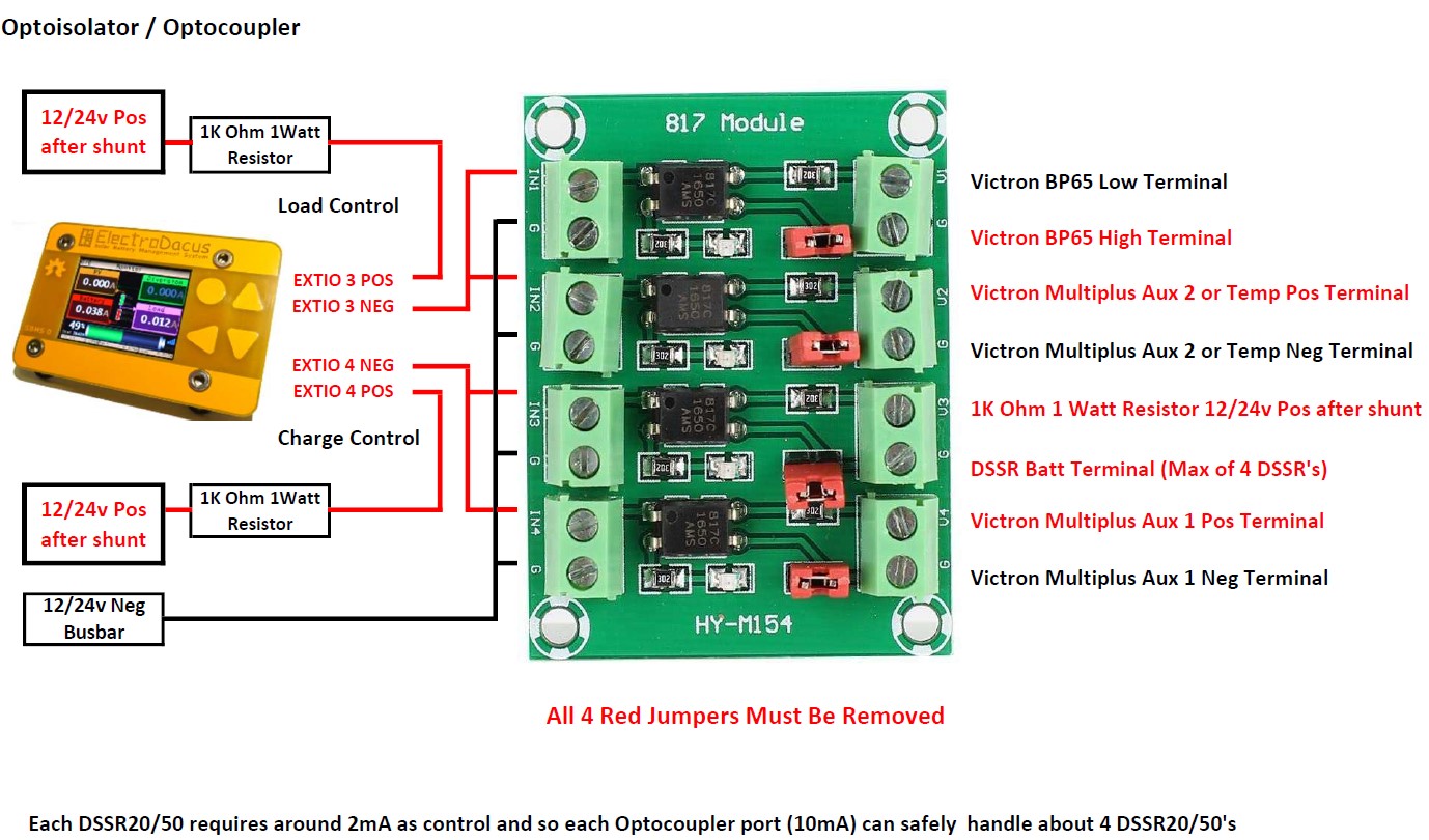
People have used this board with 4 optoisolators on it https://www.amazon.ca/Optocoupler-Converter-Anti-Interference-Isolation-Conversion/dp/B07WFGTNQC you just need to remove the red jumpers
Here is a diagram one of the users made on how he connected that board. On the output there is a 3Kohm resistor in series with opto isolator output transistor and some devices that need a bit higher current may not work thus for that case you may need to replace those resistors with a lower value or even a short. and on the input there is a 1KOhm resistor to GND already on board in series with a LED for visual indication and nothing else so you can build your own simple board if you want.
"
Nils
May 9, 2021, 11:52:55 AM5/9/21
to electrodacus
Hi Dacian,
thank you very much for the explanation. :) I will continue my planning and hope to get in my order with you soon.
Best regards,
Nils
Nils
May 9, 2021, 1:44:53 PM5/9/21
to electrodacus
Hi again,
while trying to decide on a pv panel (the roof space of our van is limited), I stumble across another question.
In SBMS0 manual it say Open Circuit Voltage of PV is max 49 V. In DSSR20 manual it says OCV is 51 V.
I am planning on using a single large high power panel like:
- LG Solar LG415N2T-L5 NeON 2 BiFacial (415 Wp, 49,2 V OCV),
- JaSolar JAM66S-30-495 (495 Wp, 45,5 V OCV)
- Trina Vertex Series 400 Wp+ (405 Wp, 41,20V OCV)
Am I correct to assume that all these panels should work okay and that there is no real benefit (but also no problem) to use high OCV panels as the panel will act as a constant current source when connected to the 24 V LiFePo through DSSR20 and therefore limit the voltage anyway (power will be limited too, of course).
Best regards,
Nils
PS: Hope it's okay to stay within my thread even if it's a little off topic.
Dacian Todea
May 9, 2021, 2:48:13 PM5/9/21
to electrodacus
Nils,
What you have there is LG 72 cell panel that will perform like a 415W/72 = 5.76W x 60 = 345W
JaSolar is a 66 cell panel so it will perform like 495W /66 = 7.5W x 60 = 450W
Trina is a 60 cell panel so it will work at max power point or very close to but it has slightly larger cells than typical 60 cell panels that is why is slightly larger at 1.75m x 1.1m vs typical panels at 1.65m x 1m thus the extra output power but similar efficiency.
So if size of panels and cost is not important and you want to have just a single panel then out of the 3 the JaSolar will perform the best puting 14 to 15A in to your battery but all those 3 panels can be handled by the DSSR20.
But the Trina will perform very close to that 13 to 14A so not sure is worth the extra size and weight plus likely extra cost for the JaSolar.
Nils
May 10, 2021, 1:09:56 AM5/10/21
to electrodacus
Hi Dacian,
thanks for the clear explanation. Now I understand, what Trina and Ja Solar are doing, when speaking about 120 / 132 cell panels. This confused me. But in the end these panels actually seem to consist out of two paralleled "standard PV panels" giving us the same voltage as an 60 / 66 cell panel.
I do understand your calculations as the power will be limited by the voltage drop to battery voltage compared to Pmax of the panel. Therefore extra cells will not give any extra benefit.
What still is a black box for me: How can the current be higher than the max advertised values? Let's take the Trina Vertex 405 Wp panel for example: The I_MPP is advertised as 11,77 A, the I_SC is 12,34 A (STC values). Taking you calculated estimated these current values would be exceeded by quite a bit? How is that possible?
Thanks again and have a great day,
Nils
Dacian Todea
May 10, 2021, 3:33:44 PM5/10/21
to electrodacus
Nils,
Yes more recent panels cut the cells in two halves and then build tow 60 or 66 cell panels that are in parallel but in a single one. This way the traces connecting the cells are shorter lower resistance as they combine in the middle of the panel and it also has the advantage that if the upper or lower side of the panel is shaded it will not affect the other half.
My 260W 60 cell panels are rated 8.5A max power point and I get about 10A in a cold spring day as it is the case now.
I managed to find the spec sheet for the Trina Vertex https://www.pvo-int.com/wp-content/uploads/2020/11/Datasheet-Trina-Vertex-S-TSM-390-405-DE09.08-1500V-Black-frame.pdf
You can see the first graph with curent vs voltage at STC meaning +25C cell temperature and 1000W/m2 solar iradiance.
You can get slightly more than 1000W/m2 especially if there are some clouds that reflect extrasolar on the panel and max power point is calculated as max power thus a higher voltage will help get higher power as long as current is not dropping to much and at STC for those panels the 395W is obtained at 34V and 11.62A = 395.08W but since battery voltage is lower around 27V in most cases in same conditions you will get basically the short circuit current of 12.21A so 329.67W
Now you need to consider that in real world you will have maybe a 5% to 10% voltage drop on the wires depending on how long the wires are and if you have a single panel or two in parallel then there is another 7 to 8% drop on a DC-DC converter (MPPT) so at least 5% + 7% loss for cable + MPPT thus 12% loss in total gettin you 88% of that 395W in to battery with a quality MPPT and average PV cable length vs the DSSR20 where voltage drop on cable is completely eliminated (it of course exists same 5%) but that 5% voltage drop will not affect the current it will still be 12.21A at 27V on battery and 28.35V at the panel the current is the same. If voltage drop was to be higher say 20% then current will start to drop.
And so in this scenario you have MPPT 88% efficiency vs DSSR20 84% efficiency.
But for STC value to be real you need to have ambient temperature around -10C as only then the panel will have +25C so it needs to be a cold winter day. In spring or summer panel will have higher temperature and max power point voltage will drop while current will increase slightly and so in those conditions the MPPT will become equal with DSSR20 and at some point MPPPT will become less efficient than DSSR20 as it will always need to have that 6 to 8% drop on the DC-DC converter part of the MPPT thus in average over an year assuming there is also cold climate at your location the MPPT will be similar in efficiency with DSSR20 so yes you will most of the time see 13 to 14A from those Trina solar panels.
The 1000W/m2 solar irradiation is an average round number you can get 1100W/m2 on ground in many situations.
Nils
May 12, 2021, 3:25:50 PM5/12/21
to electrodacus
Hi Dacian,
sorry for my late reply. Thanks again for the great explanation. I will then go ahead and choose a "high power" 60 cell / 120 half cell panel. You are right about the JA Solar. It's larger and heavier. Also I might be lucky and get an all black version of the Vertex S (would fit the car a lot better visually).
I am working on my electrical setup drawings at the moment, I will post here once I am done to share some of my ideas with the community. And of course get any input you guys want to share. :)
Nils
May 13, 2021, 12:28:14 PM5/13/21
to electrodacus
Hi everyone,
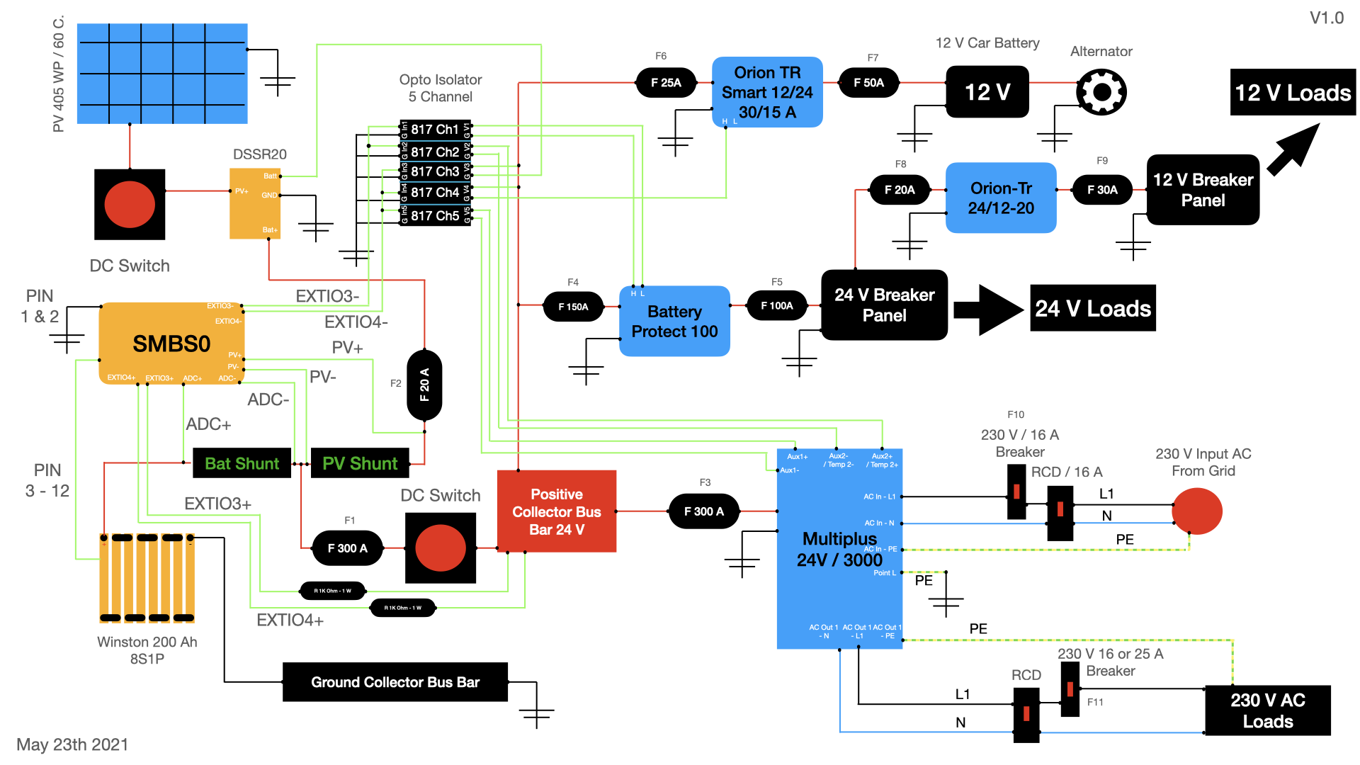
I put today's national holiday in Germany to good use and finished the first draft (V1.0) of my power setup. Input is highly appreciated. :)
A few notes:
- I am planning to use three 2-channel-opto isolator boards (gives me one spare channel for later additions)
- I changed the initial design: The 12 V DC step down is now connected behind the Battery Protect and will NOT be directly controlled by SMBS0 - more cost efficient.
- I added some unique IDs to each of the fuses as I am not sure, if I calculated all the values correctly. So it's easier to reference a certain fuse.
- Black dots represent electronic connections. It got quite confusing with all the green signal wires, so I added dots to show where actual connection should happen. Any other wire crossings are simply that: non conductive crossings.
I highly appreciate any input.
Best regards,
Nils
Attached as PNG and PDF (for better resolution).
Dacian Todea
May 13, 2021, 12:58:15 PM5/13/21
to electrodacus
Nils,
All seems OK.
The Orion Smart used as battery to battery charger to charge from alternator can be connected to the PV shunt (I know it is called PV but you can connect there any separate charge source). Not sure if that is a 30A charger or a 15A charger as fusses will be OK if is a 15A charger but if it is 30A on the output it will require more than 60A from the 12V side.
I do not think you need the F3 as you already have the F1 with same value.
That DC switch after F1 will also disable all your charge sources as all your EXT IOx are supplied from that buss bar after the switch. Is not a problem just a remark in case you didn't wanted that.
Nils
May 13, 2021, 1:37:46 PM5/13/21
to electrodacus
Hi Dacian,
thank you so much for feedback. :)
- Regarding F1/F3: Thanks, that actually was a typo. F3 must be 200 A rated.
- The Orion Charger is a 15 A charger on 24 V side. So around 30 A input from 12 V side.
- Good point: I moved the EXTIOx supply in front of the switch, but after F1 fuse. Now that I am thinking about it, I also could go in front of F1 as well. A 300 A fuse will not help a lot as in a failure event EXTIOx will be damaged way before that fuse blows. It's my understanding that the 1K ohm / 1W resistors will act as a fuse for the EXTIOx, right?
- Regarding the charging connection: Very good to know. I think I still will stick with the charger connection at the battery shunt, if that's okay, too? This way I will get clean PV stats on the SBMS0, which I am really interested in. (I am hoping to do not need the alternator charging as often anyways.)
I updated and attached the schematics.
Best,
Nils
Dacian Todea
May 13, 2021, 2:06:08 PM5/13/21
to electrodacus
Nils,
Yes the EXt IOx are protected by the resistor as any short circuit after the resistor will result in a very small current below 50mA and can no damage anything so you can connect the EXT IOx resistors before the fuse so if for any reason that fuse is damaged at least your battery is still charged.
Yes you can keep the alternator charging on the Battery shunt is just that the Load indication will not be correct as the alternator will supply the load directly and Load is calculated as the difference or sum of battery current and PV current.
Since you use the alternator charger just very occasionally or maybe even never :) then it will not make much of a difference either way.

Richard Bewza
May 13, 2021, 2:44:32 PM5/13/21
to electrodacus
Nils,
You might want to pull your opto ch3 and ch4 output side power from the same location you are pulling your EXTIO power from.
You should also add 1K resistors here as well.
Your pin 1&2 to ground must go directly to neg of cell 1. Just remove that note and change green wire note to pin 1 - 12 for clarify.
Nils
May 13, 2021, 2:56:11 PM5/13/21
to electrodacus
Thanks to both of you for your clarifications and suggestions.
Dacian, will a negativ load make the consumption statistics go backwards, when no load is present and charger is active (or charing current > combined loads)? In that case I might change over to the PV shunt for the alternator charging.
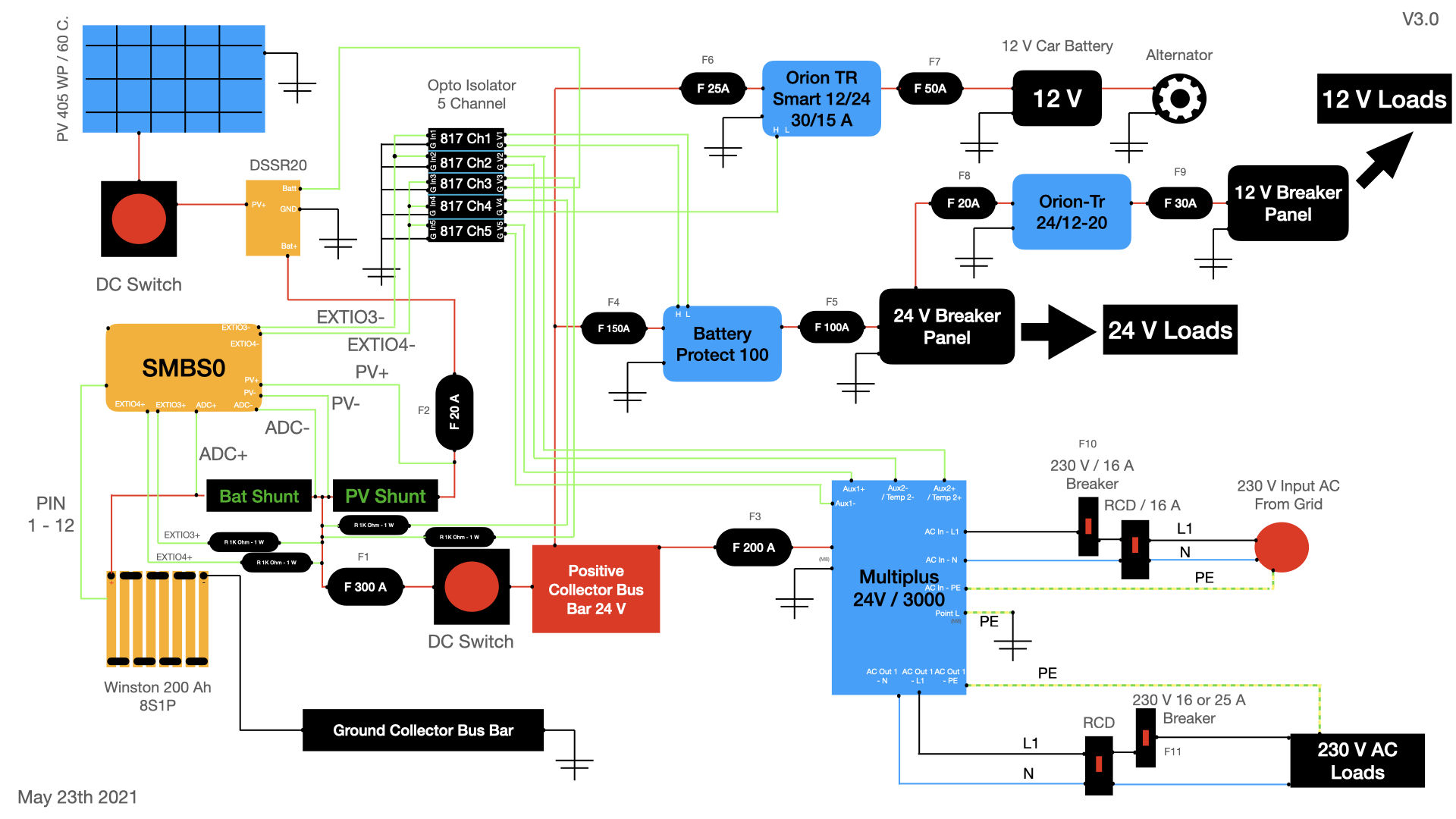
Good point, Richard. I made the updates to the schematics in V3.0. That's how you were proposing, right?
Best,
Nils
Richard Bewza
May 13, 2021, 3:20:18 PM5/13/21
to electrodacus
Nils that is exactly what I meant.
I also just noticed that both your battery protect and orian TR have high and low pins.
You are controlling them with two different methods.
You may want to read both manuals and pick one method for consistency.
I have my battery protect wired as you show.
I am not sure of the benefit of one over the other.
Dacian Todea
May 13, 2021, 3:29:33 PM5/13/21
to electrodacus
Nils,
Not quite sure I understand your question. There will be no negative load that will be a charge source.
But I should maybe give an example
Say you get 15A from PV panels that is measured by the PV shunt then say battery shunt measures +10A meaning battery is charged then 15A - 10A = 5A load so Load is calculated correctly and the Load is supplied directly from PV
Now say PV is the same 15A but battery shunt shows a -40A discharge current that means Load is 40A+15A = 55A with 15A coming directly from PV and 40A difference from battery.
Now say you add 16A from the alternator connected as you show in your diagram.
Then first example will have PV shunt sowing the 15A from PV and the battery shunt will show +26A so your Load will show as 26A - 15A = 0A because there is no such thing as a negative load but you have no idea that you have a real 5A load as the PV and alternator directly supply the Load.
Second example where will see same 15A PV and -24A battery shunt so SBMS will think you have a 15A + 24A = 39A load but it will be incorrect as you can not measure the 16A from alternator that directly supplies the Load.
So there will not be a negative load shown as there is no such thing but you will just know the PV current and the battery current (so SOC will be correctly calculated) but the Load will not be correctly calculated when that alternator charger works.
If you are much more interested in the PV generation than the Load consumption then you can have the alternator charger connected as you show.
Dacian Todea
May 13, 2021, 3:32:41 PM5/13/21
to electrodacus
Now that Richard mentioned you will want to connect that resistor from CH4 to your vehicle ignition (so charging is only done when engine is running) else you will have the started battery drained.
Nils
May 13, 2021, 3:41:55 PM5/13/21
to electrodacus
Dacian,
thanks for the great explanation. This makes perfect sense. So SBMS0 will see the charge current from the alternator charger going in to the battery in case there is no load and SOC will be monitored correctly. That's perfect.
Regarding the ignition suggestion: I understand that the Orion-TR-Smart Series has a feature applying a "smart" probing algorithm to see if the engine / alternator is running. This is done by periodic voltage measurements with load / no load cycles That's at least what I understood... :) You can read more about that in the manual on page 9: https://www.victronenergy.com/upload/documents/Orion-Tr_Smart_DC-DC_Charger_-_Non-Isolated/Orion-Tr_Smart_DC-DC_Charger-en.pdf
I think this should make the separate connection to ignition obsolete, correct?
Richard, you are right. I don't even know, why I connected the Orion-TR only via H and pull this to battery level. Following the manual it would work. But connecting to H/L pins directly (like you did on your Battery Protect) seems way more intuitive. Especially as I already put all the needed wires in the floor... :) I will updated the schematics and upload again later.
Best,
Nils
Dacian Todea
May 13, 2021, 3:53:34 PM5/13/21
to electrodacus
Nils,
If you trust that voltage based protection will protect your battery then is fine. You also need to consider voltage drop on the wires from orion to the alternator as there will be over 30A there. Ignition is usually a better option in most modern cars.
Richard Bewza
May 13, 2021, 4:16:30 PM5/13/21
to electrodacus
Nils,
Dacian's concern about the alternator voltage is warranted.
In the olden days vehicle charging systems put out 13.8 volts whenever the vehicle was running .
Modern day vehicles charge between 14 and 15 volts, float at 13.8, and sometimes charge at 12.8 to save fuel.
When my truck reduces charging to 12.8 volts I can force it to charge at 14 volts by turning on my air conditioning or headlights.
It is definitely worth investigating how your vehicle charging will work with the orian automatic settings .
Nils
May 13, 2021, 4:36:47 PM5/13/21
to electrodacus
Dacian, Richard,
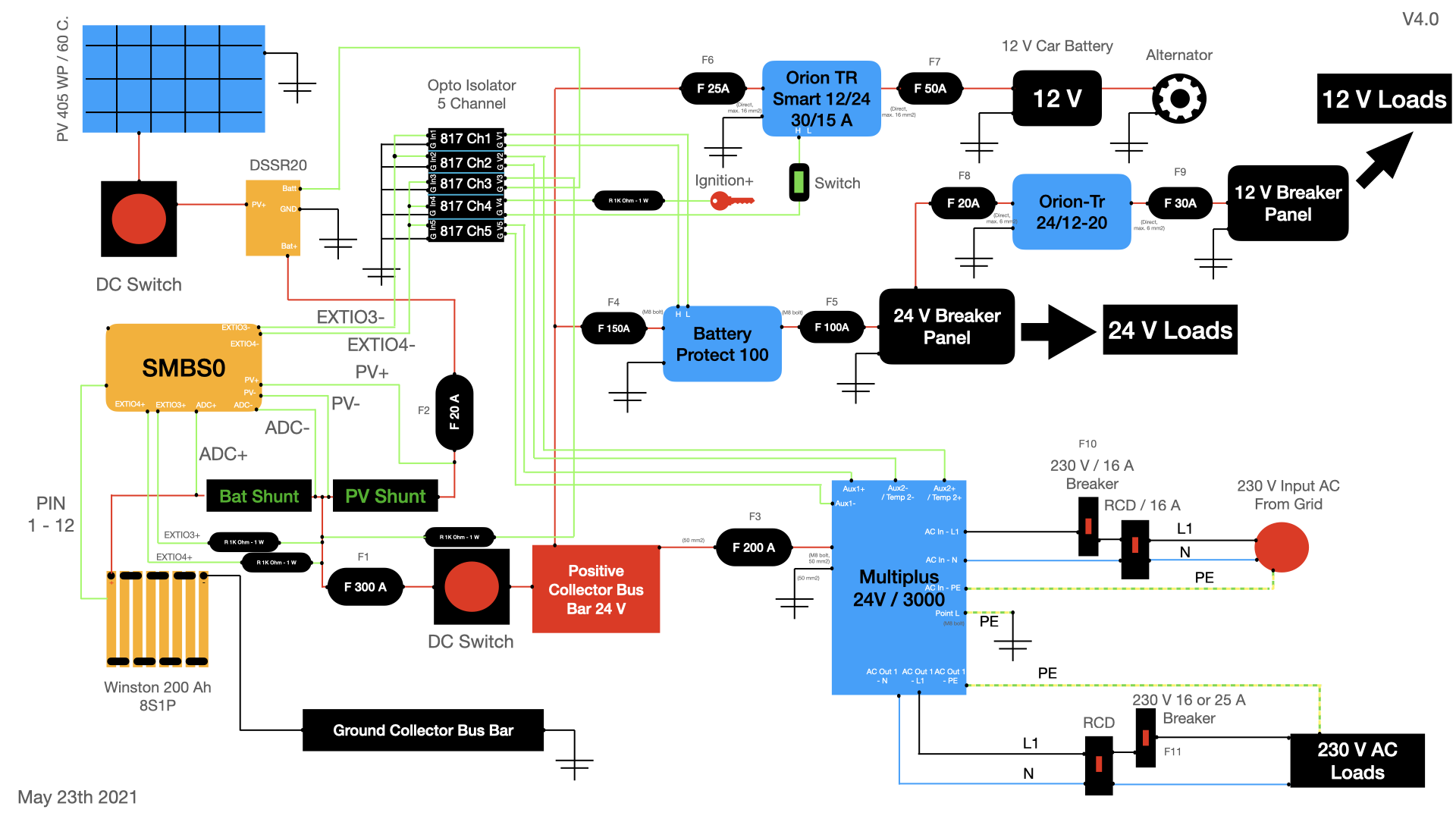
makes perfect sense- thank you for the hint. Even though the device is especially marketed for working with theses kind of "smart alternators". A short google search revealed that it will be no big effort to connect to a nearby ignition positive. Better safe than sorry, I guess. :) I also added another manual switch so I have full control over the alternator charging. These means all three following conditions have to be TRUE to use the alternator charger:
- Switch ON
- NO Over Voltage Protection Event
- Ignition ON
I updated and attached the schematics (V4.0).
Best,
Nils
Richard Bewza
May 13, 2021, 11:46:48 PM5/13/21
to electrodacus
The new orian switch you are adding can also be on the ignition wire if that ends up being easier.
I also added switches next to the resistors feeding IO3 and IO4 just because I could.
This lets me put my 5th wheel in semi-hibernation mode with batteries at 70% state of charge.
In semi-hibernation mode the SMBS0 with WIFI ends up being the only draw.
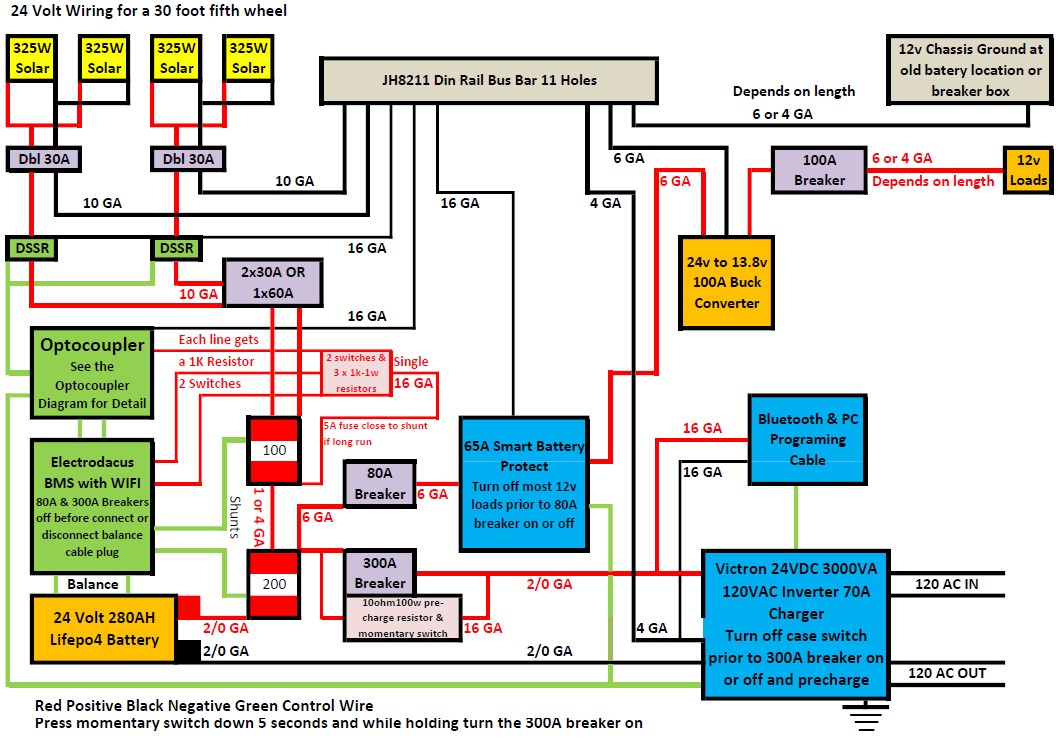
I am attaching my latest drawings of the system in my 5th wheel just in case it gives you any other ideas.
Nils
May 14, 2021, 2:21:17 AM5/14/21
to electrodacus
Hi Richard,
thank you very much for sharing your system details. Good idea, I will try to think of a practicable way to integrate some switches for EXTIO 3 / 4 feed as well.
As I am now researching suitable components, two new questions emerged. Maybe someone has some idea:
I am thinking about using a DC C characteristics breaker for PV applications to combine the DC switch and the F2 fuse (20A). Is it okay to have the fuse between PV panel and DSSR instead of DSSR and PV shunt? (Example for breaker: https://datasheet.eaton.com/datasheet.php?model=279129&locale=en_GB)
Speaking of shunts: There are multiple types out there. Most higher current rating models do not seem to be shipped with a mounting plate / isolator plate. You can see some of theses "nacked" shunt models in the SBMS0 manual on p7 (the left and right ones). Is there a best practice way to mount theses types of shunts properly?
Best,
Nils
Dacian Todea
May 14, 2021, 1:53:04 PM5/14/21
to electrodacus
Nils,
The F2 needs to be close to (immediately after) the PV shunt as the role is to protect the wire between PV shunt and DSSR20 from a possible short circuit since then huge current from battery can flow through that.
On the other direction current is limited by the amount of light so that can never exceed the fuse or breaker current.
The DSSR20 can be super close to PV shunt that a fuse or breaker may not be needed with the short wire protected in to a cabinet.
Usually the battery shunt, PV shunt and F1, F2 will be inside an enclosure just next to the battery if not in the battery box and then the two wires coming out of that are protected by F1 and F2 respectively (of course they could be fuses or breakers).
Those breakers you show are unidirectional and will not work on the PV side as fault current is usually from battery to PV (DSSR20) while normal current flows in the other direction from PV to battery so you will need to use two of those breakers installed in opposite direction to protect both ways. I use this ones that are DC rated but bidirectional https://www.amazon.com/Miniature-Circuit-Breaker-Protection-Installation/dp/B06XDZPQ3H and there may be some others that are the same.
You can see some examples of shunts in my post here https://groups.google.com/g/electrodacus/c/ReL-z6vGFdw/m/vsmKm0grAQAJ
Nils
May 16, 2021, 6:04:08 AM5/16/21
to electrodacus
Dacian,
thank you for the explanation and links.
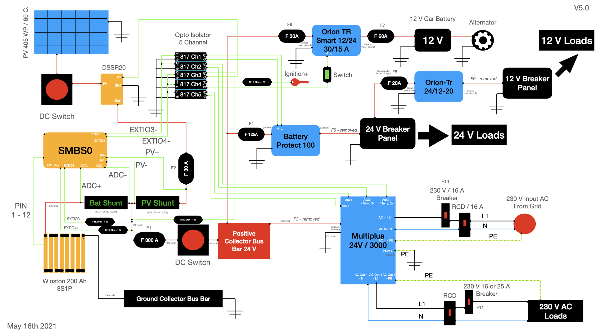
I revised my schematics again after trying to plan a smart way of wiring the system (research available fuse holder, fuses, etc). I adapted some of the fuse values and removed a few of the fuses. I would appreciate another pair of professional eyes reviewing V5.0. :)
Changes:
- F1(between battery shunt and positive bus bar) is now the only fuse between battery and inverter via the positive bus bar.
- F2 (between PV shunt and DSSR20) is now 30A instead of 20A (for design reasons). Is that higher value still okay for the situation you described above? I will use a standard melting fuse. Not the breaker liked above. For switching PV I will stick to a high current rated DC switch as initially planned.
- F3 (between positive bus bar and inverter) is removed as it actually was meant to be 300A (as I drew in V1.0, but for some reason thought I made a typo after your first comment). As Victron recommends a 300 A fuse between battery and inverter F1 will take over this role. I hope that makes sense.
- F4 (between positive busbar and BP100) is adapted to 125 A (from 100 A in previous design).
- F5 (between BP100 and 24 V fuse panel) is removed. After the Battery Protect 100 there will be a fuse box, fusing each load separately. Or should I fuse the fuse box as well?
- F6 (Orion TR Charger Output) is adapted to 30 A (from 25 A in previous design) as recommended by Victron.
- F7 (Orion TR Charger Input) is adapted to 60 A (from 50 A in previous design) as recommended by Victron.
- F8 (Orion TR DC/DC Input) is removed as a separate fuse, as the Orion TR already has a 20A input fuse.
- F9 (between Orion TR Output and 12 V fuse panel) is removed. After the Orion TR there will be a fuse box, fusing each load separately. Or should I fuse the fuse box as well? (see #5)
Thanks again.
Best,
Nils
Dacian Todea
May 16, 2021, 1:21:10 PM5/16/21
to electrodacus
All looks OK based on a quick look. The F4 protects the wire from positive busbar to BP100 so should be installed immediately after the busbar not close to BP100 as it will do nothing there.
Richard Bewza
May 16, 2021, 8:35:14 PM5/16/21
to electrodacus
Nils,
You should add a pre-charge resistor and momentary switch connected to each side of your main DC switch.
This will save you damaging the switch or blowing your 300 amp fuse or even damaging your muliplus inverter.
Lots of options on the correct size 10 to 30 ohms 50 to 100 watts.
I used a 10 ohm 100 watt resistor and hold down the momentary switch around 5 seconds to charge the inverter capacitors before turning on main switch.
Nils
May 17, 2021, 5:49:03 AM5/17/21
to electrodacus
Dacian,
thanks for the short review. Appreciate it! All fuses will be placed close to current source. As space is limited anyway, wires will be short in most places as well. Also thank you for the link to the shunt thread. I learnt a lot again
Richard,
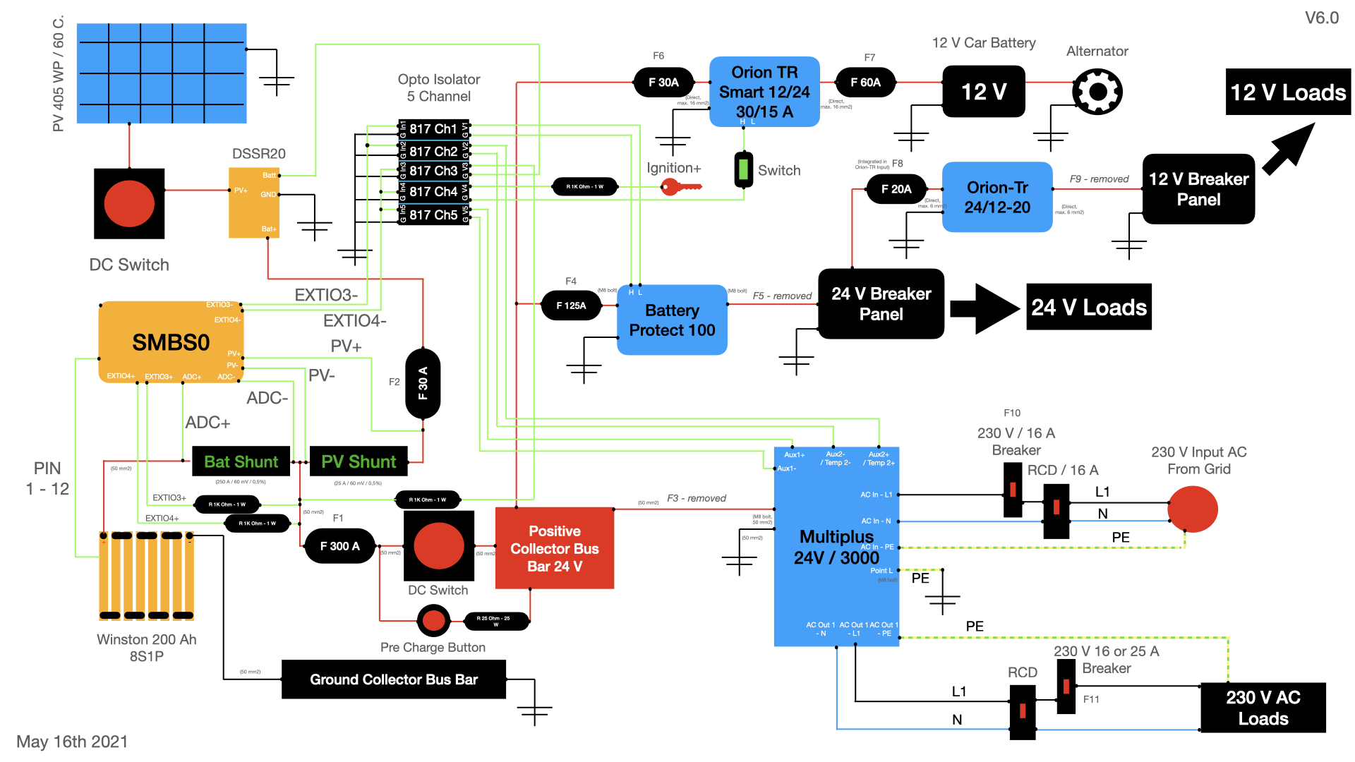
Thanks for the hint. I was reading up on that. I decided on a 15 Ohm / 25 W resistor (Based on the calculations made here: https://diysolarforum.com/resources/inverter-disconnect-switch-with-precharge.60/)
I also updated the schematics (V6.0).
Best,
Nils

Peter
May 17, 2021, 6:53:04 AM5/17/21
to electrodacus
Hi Nils.
Thank you and others here for great inspiration. This is wonderful community here.
Maybe on that new pre-charge button line I would put first resistor and then the precharge button. The resistor would act as a fuse to protect that little cable around pre-charge button. It's probably just a silly detail.
Just a general note for camper van project: I would suggest to reconsider if you really need Orion Tr and 12V breaker panel.
In my camper van project (https://groups.google.com/g/electrodacus/c/ioJeZUEUuLA) I also planned 12V but in the end I found out that I dont need it. If I could not find 24V variant of appliance, I use 12V version powered via PWM (~100% power efficiency, for example fans) or with little cheap buck DC/DC converter witch will be bonded and optimized with the appliance. So the DC/DC converter will be turned on only with the appliance.This way I wont have any nonstop idle consumption of big DC/DC converter - with Orion-Tr you will burn 0.06 kWh every day for nothing (idle consumption 2.5W). I would rather spend those few watts for 24/7 internet access (mobile phone) and/or Raspberri PI server.
I found out that I need special 5V power line to support for many sensors, MCUs (ESPs), Raspberri pi server (running also with Home Assistant), mobile phone (acting as control panel and internet access), USB chargers... 5V is also needed for digital LED strips.
Dne pondělí 17. května 2021 v 11:49:03 UTC+2 uživatel Nils napsal:
Nils
May 17, 2021, 11:44:08 AM5/17/21
to electrodacus
Hi Peter,
thank you for your valuable input. Sound interesting, I will look into that. I received the Orion TR DC/DC a few days ago and will do some measurements. Maybe I will consider your method - very smart!
As we already discussing the details, another question:
Dacian recommends using CAT cables for EXTIO and other connections from the I/O ports. Makes perfect sense. Dirt cheap and good quality wire. Now CAT Cables (at least as far as I know) often are made from solid copper. In Germany we have to follow a lot of laws and regulations when it comes to vehicles. Unfortunately solid wires are a NO GO in this application. This is related to the possibility of cracking when used under mechanical loads (vibrations) for a longer period of time. We sure could discuss the meaningfulness of those rules. But I have to takes them as a given at this point.
Therefore: Is it okay to connect wires made by multiple conductors to the ports directly or do you recommend using small ferrules? If it was my choice I simply would slam the damn CAT cable in there... :D
Best,
Nils
Peter
May 17, 2021, 12:10:52 PM5/17/21
to electrodacus
Another option is to put tin on the ends of stranded wires. You will get better conductivity than with ferrules.
Dne pondělí 17. května 2021 v 17:44:08 UTC+2 uživatel Nils napsal:
Nils
May 24, 2021, 4:30:03 AM5/24/21
to electrodacus
Hi everyone,
I updated the schematics once more (V7.0) and switched the order of the momentary switch and the precharge resistor to protect the small switch as suggested.
As I found some time to check out the opto isolator boards, yesterday,, I already tested the remote wiring with the Victron Battery Protect 100 and the Orion TR Smart DC/DC charger. Works well on both 12 V and 24 V input levels. Perfect.
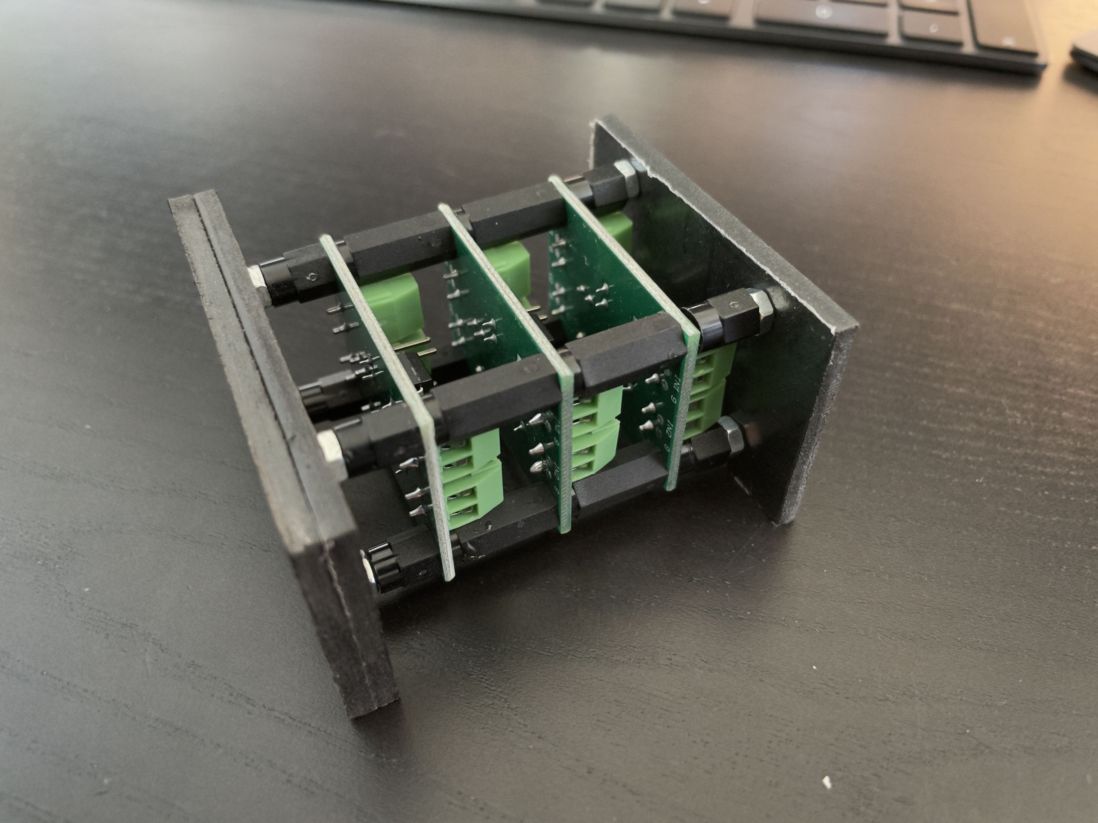
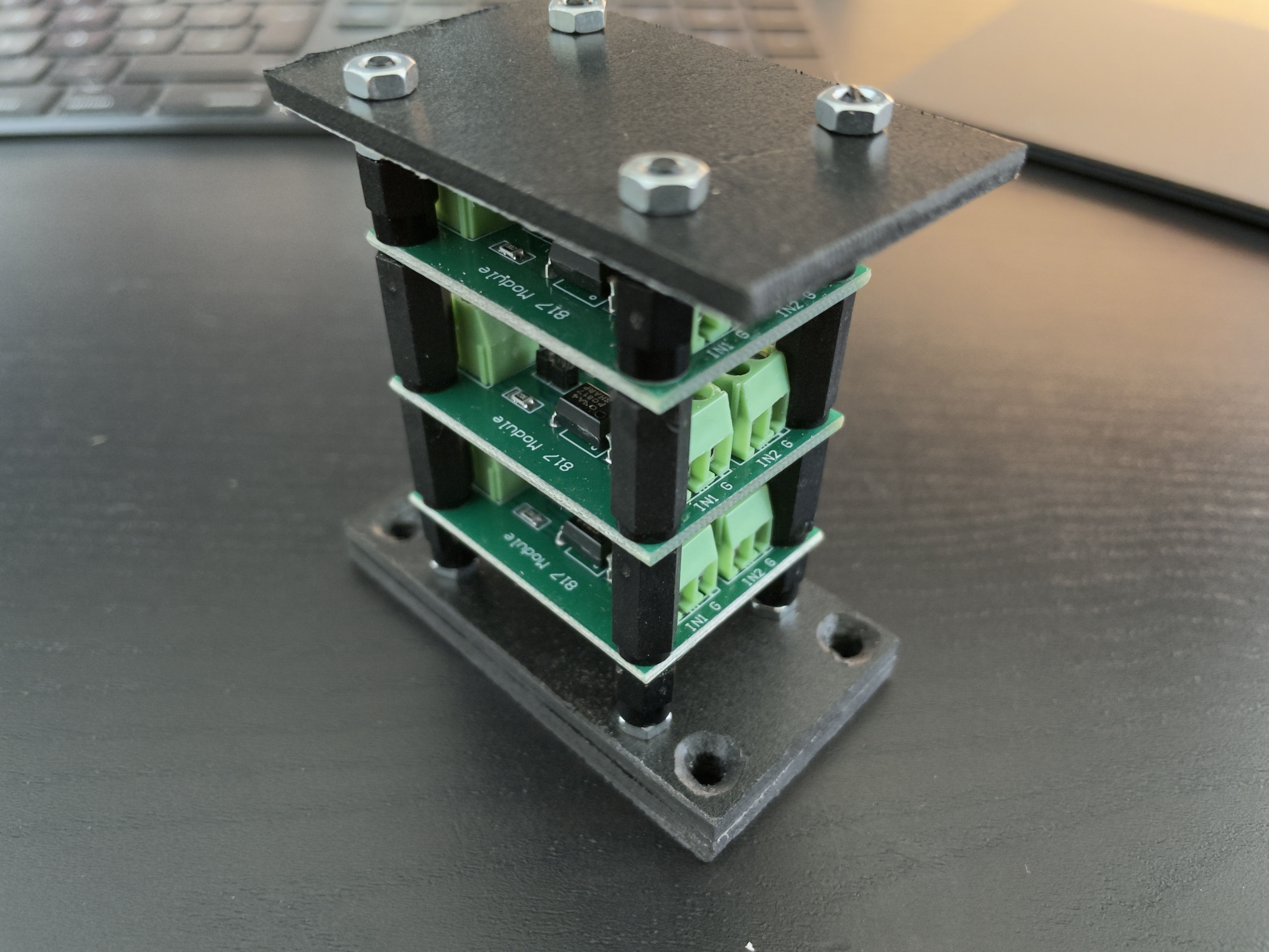
I also came up with a somewhat clean way to mount six opto channels on a small surface (three board, 2 channels each). Pictures are attached. They might be helpful for someone.
Now I am waiting for all the shipments to arrive to start the built.
Best,
Nils
Richard Bewza
May 24, 2021, 1:40:29 PM5/24/21
to electrodacus
Nils,
Version seven drawing looks great and is easy to understand.
When you actually start to build, make sure the fuses and resistors are close to the power sources as one of their main functions is to protect from wires that may get chafed. Fuse six for example should be closer to the battery source but not before fuse four if they're sharing a wire.
There is a trend to much larger solar arrays on RV's. Your current solar design will produce 10-14 amps under ideal conditions. With a large 200 amp battery bank you can be safely applying 100 amps of charging. If there is a way to install 2000 to 3000 Watts of solar on your RV you would be much happier in the long run. People are starting to build racks to mount their solar panels above the skylights and air conditioners. This eliminates shading problems and allows for a much larger array. This larger solar array would also allow you to run the air conditioner or electric heater all day long on sunny days.
Cheers ,
Richard
Dacian Todea
May 24, 2021, 4:09:42 PM5/24/21
to electrodacus
Nils,
All seems to look good.
Richard,
0.5C is to high of a charge rate the ideal / optimum will be 0.2C to 0.25C as that means in a typical sunny day you can fully charge an empty battery (should not be the case) and also that charge rate is handled easily by any type of LiFePO4
Some have very small RV's so they can not fit larger PV array I think that is the case for Nils.
And yes in his case the main limitation is the solar PV panel spec here https://www.pvo-int.com/wp-content/uploads/2020/11/Datasheet-Trina-Vertex-S-TSM-390-405-DE09.08-1500V-Black-frame.pdf
That panel will put out 12 to 14A so about 1.5 to 2kWh per day and that is the limitation as battery is 5kWh capaicty but he can use in average 1 to 1.5kWh/day because of the solar panel limitation.
In a cloudy overcast day the panel will only produce 100 to 150Wh per day so yes if he will have had 3 to 4 of those panels (what I consider a good match) the panels will have produced 0.5kWh/day in some of the worse overcast cloudy day possibly half of the average daily consumption and then he will not have needed any other source other than solar PV with 30 to 40kWh/month average consumption.
Nils
May 25, 2021, 2:01:35 AM5/25/21
to electrodacus
Hi Richard, Hi Dacian,
thanks for your feedback. Of course, all fuses will be placed close to current source. Good you pointed it out in text, as I was simply placing them somewhere in the schematics to keep the line chaos to a minimum. :)
Dacian is exactly right. We are converting MB Sprinter medium wheel base (meaning 1,4 x 3,2 m roof space). A third of that is occupied by a roof vent. So a single large panel is all that is going to fit up there while staying within regulations and not making it look too funny...
I am ware that the panel will not be able to fill up the battery within one day. On the other hand I chose the battery capacity in a way, that we should be okay. In most cases we will not need the cooking top everyday. Basic consumption is low compared to PV input power on an average day.
Induction cooking also is highly efficient. My first tests with a single "burner" induction top show about 0,6 to 0,9 kWh for the preparation of decent meal including some longer cooking (20 minutes or so). It's not like you would use the maximum 2000 W power of the induction cooker all the time (unless you want to burn your food VERY quickly). I will report back how the whole plan plays out. :)
Can't wait to continue the built.
Best,
Nils
Peter
May 25, 2021, 2:51:54 AM5/25/21
to electrodacus
Hi Nils,
I would recommend to use different PV shunt.
When getting 14A from solar, with yours 25A/60mV you will be loosing/heating on this shunt 0.06/25*14*14 = 0.47W.
I would recommend for example 200A/50mV. In that case you will loose only 0.05/200*14*14 = 0.05W and the resolution will still be acceptable 0.27W.
Fitting as many PVs to van roof is challenging part of the build. I decided for
VBHN250SJ25 because their longer side is only 158 cm so they can be
transversely mounted. I also dont want it to look funny so I am planning thin aluminium roof rack around it which will also enable tilting of the panels with two linear actuators. That "roof rack" will also hide roof windows so I think the van will be more stealthy when not showing roof windows from the side.
P.
Dne úterý 25. května 2021 v 8:01:35 UTC+2 uživatel Nils napsal:
Dacian Todea
May 25, 2021, 2:46:20 PM5/25/21
to electrodacus
Peter,
The 25A 60mV shunt is perfectly adequate to measure 14A and that 0.47W loss as heat is just nothing in exchange for that small amount of heat loss he gets very high current reading resolution.
There is quite a bit of complication in adding a tilting PV panel mount and those panels are 72 cell panels so you will need an MPPT then that will be quite a bit more heat loss plus the extra expense of an MPPT
Peter
May 25, 2021, 4:13:34 PM5/25/21
to electrodacus
Dacian,
Yes, true, 25A 50mV is adequate and with high reading resolution.
But if it would be my van with 405W of solar, I would probably try to optimize it as much as possible. Only my opinion, nothing more.
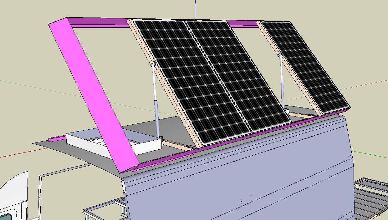
I know tilting is complicated. But when I saw how big effect tilting has.. (https://www.youtube.com/watch?v=wRHdZ2CregM)
I already have all the parts needed so I will try to go for it. I think it fits my build - 15kWh battery with PVs only 750W, I can do some tilted charging days from time to time when SOC is under 50%. I also plan charging eBikes in the van..
Yes, I must take MPPT. :-(
Dne úterý 25. května 2021 v 20:46:20 UTC+2 uživatel electr...@gmail.com napsal:
Dacian Todea
May 25, 2021, 5:54:04 PM5/25/21
to electrodacus
Peter
You are talking about 0.1% loss on that shunt if you get a shunt with 2x the rating it will still be 0.05% loss and I do not think it is significant in any way and not worth considering.That test was done very early in the morning with sunt still at horizont. In probably 2 or 3 hours the sun will be at way better angle to the panels and likely with typical setup the battery will be fully charged before noon with no tilting and maybe with perfect vehicle orientation and tilt you speed that up by one hour still after noon all energy will remain mostly unused.
Not sure tilting will provide him with any benefit and very likely it will not be able to ever compensate for the extra cost in fuel due to extra drag from the large box on top of the vehicle.
I think that guy is in US where vehicle modifications are much more relaxed compared to Europe.
Nils
May 26, 2021, 9:50:19 AM5/26/21
to electrodacus
Dacian, Peter,
Anyway, thanks for the input. I already ordere the shunts, which have been manufactured for me, as all other supplies have lead-times > 2 months at the moment. But I highly appreciate the input, Peter.
I like the tilt construction, but it's nothing for our use case. I think I will rely on alternator charging (or shore power), if the battery really should get low. In the long run I still will be able to upgrade the PV panel / shunt for more PV power. I would love to see the finished built, maybe you will share with us later?
Best,
Nils
Nils
May 30, 2021, 3:14:04 PM5/30/21
to electrodacus
Hi Dacian,
I received my SBMS0 yesterday, after dealing with customs. First of all: THANK YOU. This little thing is an awesome device. And it's worthy to mention how well you build these units. The quality is outstanding!
I have built a test setup to try out the basic functions and familiarize myself with the abundance of options. The setup is simple: 4S Li-Ion pack (10 Ah) connected to bat shunt (250 A / 60 mV) connected to an Juni 406 B RC charger (simulating load or charge source). GND of battery is directly connected to the charger in this setup. Only ADC1n/ADC1p connections besides the cell wires. Nothing else.
Everything is working finde. There is just one quirk I can't wrap my head around: The current values measured by the bat shunt sometimes seem to be off.
Example: The charger charges with a current of 4,5 A. The shunt only measures 3,5 A (so around 1 A less than real current). Now I switch to discharge with identical current (4,5 A) and the SBMS is showing a discharge current of 8 A+. Both currents verified with clamp multimeter (around 4,45 A).
The ADC calibrated with a zero value (or neutral value) of 32749 steps accord to diagnostic menu. I tried re-starting / re-calibrating the device multiple times and variants: 1) Charger connected, but no current flowing, of course; 2) nothing connected to load side of bat shunt.
I got it working for a two single attempt and readings were correct. The second time I managed to almost get in a full charge / discharge cycle (around 4h working time). On the last few Ah of the charging cycle the SBMS0 started showing the "wrong" values again. Nothing changed for the setup - as far as I can see.
The resistance for the shunt is set to: 0,06 V / 250 A = 0,24 mOhm. While it was working correctly, I trimmed the resistance just a little bit above that value to get accurate readings.
To check if the shunt is okay, I repeated a discharge with 2A and charged with 2A (while SMBS0 NOT connected) and measured the corresponding voltage drop on the shunt, which was identical but reversed in polarity both times. So seems okay, too.
Is there anything I am missing? Is the wiring of the ADCs really sensitive? Maybe you can push me in the right direction... :)
Thanks again and best regards,
Nils
Dacian Todea
May 30, 2021, 6:41:58 PM5/30/21
to electrodacus
Nils,
Please check again that you Battery shunt resistance value is set at 0.2400mOhm (not the PV shunt) then go to device settings and push the Save Device Settings button so that if you power cycle the SBMS0 the value remains the same.
Also current shunt is directly connected to battery+ (nothing between the shunt and the battery+ terminal) and reading should be correct within the tolerance of the current shunt so 1 or 2% depending on the shunt quality.
Nils
Jun 3, 2021, 2:51:33 AM6/3/21
to electrodacus
Dacian,
thanks for your input and sorry for the delayed reply. Everything was connected and set up right. I identified the error in some weak connections at one of the shunt measurement points. I used crocodile clips for my temporary installation, which caused this behaviour.
After tweaking the connections, readings seem to be super accurate. As I had the shunts manufactured for me the shunt have been calibrated to even 0.5 % tolerance. :)
Hope to continue with the built soon. Finished my bus bars from thick copper bars a few days ago and waiting for other parts to arrive.
Best,
Nils
Dacian Todea
Jun 3, 2021, 12:38:10 PM6/3/21
to electrodacus
Nils,
Glad you found the problem. Is not a problem even if shunt will have had much higher tolerance as you can trim that from the SBMS0 by adjusting the shunt resistance.
Nils
Jun 28, 2021, 9:54:40 AM6/28/21
to electrodacus
Hi,
I thought I would report back after fully putting the system together last weekend.
Everything works as planned - as far as I can tell from the little experience gained so far. The SBMS is doing a great job and the control via the opto isolator board works finde as well.
Dacian, do you have any experiences when it comes to max ambient temperature? Today we had a very sunny day (with around 28 C outside). Inside our black van temps have reached around 38 C so far (ext temp sensor on Winston cell). Which will be a likely / standard scenario when traveling further south in Europe. SBMS reached 46 C while balancing. The car was parked in full sunlight for the last 7 h.
Is there any maximum temp you recommend not to exceed?
I will keep you updated as soon as I made some more measurements. by the way: Today the Trina panel pushed around 12 A / 340 W, which is nice. With some cloud diffusion I can see getting 13 to 14 A, too.
Best,
Nils
Dacian Todea
Jun 28, 2021, 11:52:31 AM6/28/21
to electrodacus
Nils,
There is only one hard coded temperature for the external temperature sensor and that is +65C and at that temperature the SBMS0 will turn OFF both charge and discharge current but you should not have the battery at this temperature anyway.
For the internal SBMS temperature there is no actual limit and should be fine as long as things do not start to melt thus 46 or even 60C internal SBMS temperature is no problem.
Of course battery calendar aging degradation will double for about each 10C in temperature increase.
Of course battery calendar aging degradation will double for about each 10C in temperature increase.
Yes I expected up to around 12A form the 340W panels and I get up to 10A from 260W panels in right conditions and with edge of cloud effect I can see up to 11 or 12A for a few seconds.
Nils
Jun 28, 2021, 12:00:15 PM6/28/21
to electrodacus
Hi Dacian,
thanks for confirming the temperature situation. That is what I was guessing. In regards to cell aging: Well that's what they were bought for. I guess there is no real alternative to this temperature range exposure due to winter / summer changes in a vehicle. I hope they still will last a long time. Especially as SBMS standard Cut off values are nicely conservative. :)
I think I will monitor the temperature over the next months, just out of curiosity.
Best,
Nils
Nils
Sep 5, 2021, 3:18:44 AM9/5/21
to electrodacus
Hi Dacian,
the system is running for some month straight now. Everything works fine so far.
I just noticed one thing I can't wrap my head around. In the evening hours, when PV input is very low, the SBMS0 starts showing a direct PV to load transfer, I do not understand.
In these situations the charge FET ist on, so no OVP enabled, thus charging is allowed. Still the SBMS shows a small power (around 8 W dropping to 2 W with setting sun) going straight to load even there is nothing on the load side drawing power.
I tried to experiment a little bit:
Turning PV off (switch) - PV drops to 0 W, load value drops to idle consumption (1W) and battery takes over. (Battery to load is now shown correctly)
Turninng PV on, but main load switch off - the "ghost" load value persists. In reality there is only a very small current drawn by the Opto Isolators (below the accuracy of my shunts) in this situation.
A single digital wattage is shown running from PV to Load. Sometimes the whole thing jumps from PV to Load to PV to Battery. But only for a fraction of second before going back to PV to Load.
During the day, everything seems to be fine, though. Functionally also seems independent of these random numbers.
Maybe you got a hint for me?
Thanks and have a great day,
Nils
Nils
Sep 5, 2021, 3:26:22 AM9/5/21
to electrodacus
Oh, I forgot to mention an important fact: The whole time (except for the situation where PV is off) the SMBS shows 0W for battery. So no charging or discharging current, even tough charging would be allowed.
Dacian Todea
Sep 5, 2021, 1:34:21 PM9/5/21
to electrodacus
You switched to Watt view and there resolution is smaller than on current thus there is a rounding to maybe up to 1W
In your diagram you show only a 25A shunt for PV and a 250A shunt for battery. Is that still the case ?
A photo showing the effect you mentioned may be a bit more helpful. PV when available always supplies Load first then the difference will go to battery.
Reply all
Reply to author
Forward
0 new messages