battery protect

556 views
Skip to first unread message

Luke B

unread,
Mar 20, 2021, 5:02:09 PM3/20/21
to electrodacus
Hello Im working on building my first battery box for my van and forgot one important thing in my design.  A battery protect so I dont over discharge my lifepo4 battery.  I see that the victron bp is compatible with the sbms0 but cant seem to find any other options.  Are there other options?  Im looking for one thats about 200amps at 12v.   Ill only be using a shore charger for now, currently have the 50amp meanwell with remote on off and will wire it before the battery protect.  
When wiring it should my fuse come before or after it?  
battery>shunt>shunt>fuse>battery protect>12v circuit or
battery>shunt>shunt>battery protect>fuse> 12v circuit?

Thanks!

Will OBrien

unread,
Mar 20, 2021, 9:09:44 PM3/20/21
to electrodacus
Yes, there are various strategies for disconnecting.

I use a contactor  to disconnect my main battery load. Be aware the BP shouldn’t be used with inverters. Others replace the on/off switch with a relay on their inverters.
With my contactor, I also use a pre-charge circuit (resistor that’s connected first to prime the capacitors and prevent arcing inside my switches/contactors.

Cheers.


Casey

unread,
Mar 20, 2021, 9:33:38 PM3/20/21
to electrodacus
I use a fuse before my BatteryProtect and two after it, because the wiring on the output side is thinner, and going into distribution panels which cannot handle as much amperage anyways.  If you're using the same wiring on both sides, I'd think it's best to put the fuse between the shunt and BatteryProtect.  Consider what might happen if the side of the fuse coming after and connected to the BP is connected to battery ground.  Perhaps it would be okay but it seems safest to put fuses as early as possible.

Dacian Todea

unread,
Mar 21, 2021, 1:32:13 AM3/21/21
to electrodacus
bigredball90,

Victron BP is a fairly cost effective solution the 65A one is around $40 not sure about the 100A and 220A models.
But usually you do not need more than the 65A one for small DC loads not quite sure what you want to disconnect as inverters should not be connected there and they should have their own remote ON/OFF
Also Victron BP is unidirectional meaning you can only connect that to some Loads or to charge sources but not both as it will need to be oriented differently if it disconnects loads or charge sources.
Likely your fuse will be before the Victron battery protect if is used for loads. 

Luke B

unread,
Mar 21, 2021, 9:21:53 AM3/21/21
to electrodacus
Ahh ok that makes more sense.  I need one because I will be using alot of 12v items for my van and wont be using an inverter as much and I dont have plans to hook up solar for a while.  

Casey

unread,
Mar 21, 2021, 1:31:47 PM3/21/21
to electrodacus
The 100A and 220A models are $60 and $100 on Amazon currently, so pretty reasonable (if you want the Bluetooth-enabled models which support more flexible programming via an app those cost more, but I think this is pretty worthless given that we just use them for their remote on/off).  I just switched from a BP-65 to a BP-220, simply because 65 was a bit tight for what I've ended up having plugged in (though I didn't ever use it all at once), and it was a low enough cost to just go ahead and upgrade while I was changing almost everything else out as well.  I'm running the output out to two distribution blocks which are each rated for 100A, so 220A is a good match.  But 65A is a decent amount - realistically I probably only ever used maybe 25-30A at once, and the BP-220 is quite a bit bigger than the BP-65.  Also, the BP-65 can handle a peak usage of up to 250A for up to 30 seconds (I'm not sure what happens after 30 seconds though, maybe better not to push that limit).  It's also possible to connect multiple BatteryProtects, in case you get a smaller one and end up needing more later, although I like the simplicity of just having one bigger one.

Since we're on the subject, how should the BatteryProtect be programmed?  I set mine to voltage setting 9 and mode C, but I can't find a good explanation of what exactly mode C (Li-Ion mode) actually does, and I'm guessing that I should set the voltage to setting 0 so that it doesn't shut down too early and if for some reason it doesn't the restart voltage isn't higher than the nominal battery voltage.

bp.png

Dave McCampbell

unread,
Mar 21, 2021, 10:53:10 PM3/21/21
to electrodacus
BP 100 literature says in Li-ion mode C "Under voltage thresholds and alarm output of BP are inactive in this mode".  I take that to mean if you program BP in C and wire remote pin 2.1/H to EXTIO3/5 - control will be with the SBMS0 parameters not those programmed on the BP.  Hopefully that is correct because it is what I was planning to do instead of using the BP controls as they do not monitor cell voltages for disconnect.

Dave McCampbell

unread,
Mar 21, 2021, 11:14:55 PM3/21/21
to electrodacus
Much more on this subject in the 'Victron Smart Battery Protect- Is It Necessary' post earlier in this forum.

Dacian Todea

unread,
Mar 22, 2021, 2:01:34 AM3/22/21
to electrodacus
Yes that should be correct. I had a BP65 but only used for a few minutes before taking it apart completely destroying it to see how it is build inside and there is a post about that somewhere on this forum.

Peter Kuczynski

unread,
Mar 22, 2021, 10:03:35 AM3/22/21
to electr...@googlegroups.com
I recently removed my Victron BP 100 and the cheap chinese converter  and replaced it with a Victron 24/12 40A , I believe this has a Battery protect built in ? Someone please check me on this point. My main reason for the replacement was the old converter was only showing 12.4 volts, and the Victron is 13.8v . Because I'm powering 2 diesel heaters and a dc fridge, i read the voltage may not have been sufficient. I havent tested any of this yet. Btw, my prior POST with pictures for wiring up the BP 100 is here.
victron24-12 40a.png

Dacian Todea

unread,
Mar 22, 2021, 1:36:04 PM3/22/21
to electrodacus
Peter,

What you mean is likely that the Victron orion has remote ON/OFF. And if all you DC loads are connected to the output of this Victron Orion then you do not need the BP100 as the SBMS0 can turn OFF the Orion using that two pin remote ON/OFF connector same type as what is on the Victron BP100.

Peter Kuczynski

unread,
Mar 22, 2021, 4:17:44 PM3/22/21
to electr...@googlegroups.com
Correct, Thanks as always Dacian,

John A

unread,
Mar 24, 2021, 3:14:55 PM3/24/21
to electrodacus
I am working on a similar setup where the victron battery protect is only used to turn control (on/off) all of the DC loads connected to the output of the battery protect.  If I understand correctly, the correct setting for the battery protect for 12v lifepo4 would be "9" and "C", right?

Dave McCampbell

unread,
Mar 25, 2021, 1:31:20 AM3/25/21
to electrodacus
John.  As I understand it, if you program 'C Lithium' on the BP it will give voltage disconnect control of the BP to the SBMS0 and its settings.  Whatever voltage setting you program on the BP is inactive.  This assumes you have wiring correctly done as described above.  Control through the SBMS0 has the advantage of cell level voltage disconnect whereas the BP program can only see total voltage.  I am programming C Lithium on my BP100 as a load disconnect for my Load Buss.

Dave McCampbell

unread,
Apr 2, 2021, 11:37:15 PM4/2/21
to electrodacus

Just yesterday after several days of working on it and the multiple earlier posts, I finally got my two 100a Victron Battery Protects working with my SBMS0.  I found the Battery Protect instructions very misleading for anything other than a Victron installation.  Below, all in one place, is what I found required for BP installation with the SBMS0:

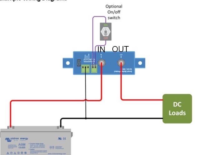
-Mount the BP such that the current coming in is wired to the big IN post on the top of the BP.  So Batt+ to IN for a load circuit, PV+/alt+/etc to IN for any charging circuit.  Then my BP OUT post wiring goes to the separate load and charge busses. 

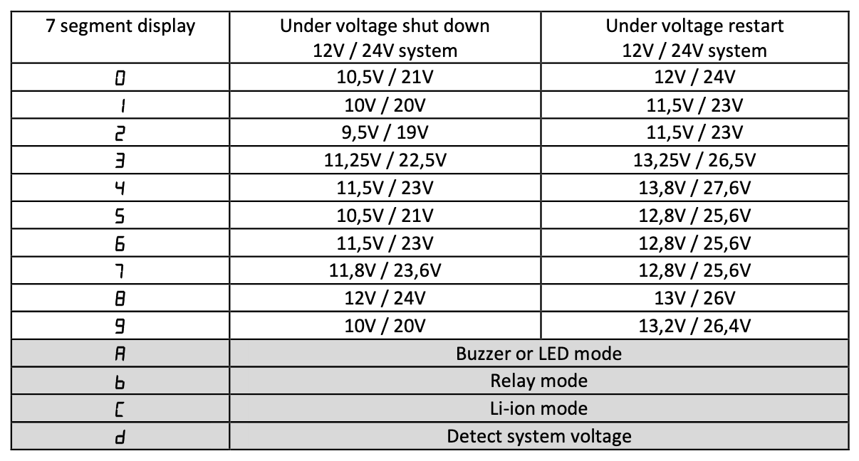
-Program the BP to C for Lithium.  In this mode voltage or SOC disconnect control of the BP goes to the SBMS0 and its settings.  Whatever voltage setting you program on the BP is inactive, so no need to do anything with that.  Also, the alarm output is inactive.

 -Wire the provided black ground wire on BP pin 1.2 to a Batt- that is always active.

-Wire the BP 2.1 pin to whichever SBMS0 EXTIOx- connection is appropriate for its use.  Use an appropriate Type setting.  I am using them to separately disconnect my load and charge busses at SBMS0 Over and Under Voltage Lock.

-Wire EXTIOx+ with appropriate resistor to Batt+.  I used a 670 ohm resistor.  The Batt+ must be active before you can activate the BP.  I wired it to the IN terminal on the BP.  

Now both the battery Protects are done and working, so on to other relays.   

Helles Helles

unread,
Nov 1, 2021, 11:07:17 AM11/1/21
to electrodacus
I"m still not clear about connecting a recent version of Victron Battery Protect 100 to Electrodacus for the purpose of load control.
One reason is that in a number of posts here and in the forum I read about an H and an L pin, but the BP100 has not such. Instead, for remote control it has a pin "2.1" and "2.2".(2nd attachment)
The manual states that "8. A remote on-off switch can be connected to the two pole connector (see figure 1) or between pin 2-1 of
the two pole connector and the battery plus."
The standard configuration for the BP 100 is illustrated in a graphic that shows two wires connected for a "remote On/Off switch"  (see 3rd attachment), and one wire for an "External on/Off signal" (see 4th attachment).
However, a third graphic shows the configuration of "Li-Ion mode" as recommended by Oberon Robinson in the Beginners Guide. This shows only one cable from 2.1 to the Victron BMS. (1st attachment)
More confusion stems from the statement in the Beginners Guide, that the "+" and "-" indicators at the EXTIOx ports are not relevant anymore, and only left for backwards compatibility to older versions.
That triggers uncertainty about the rational to connect the EXTIO3+ cable to Battery plus, even with a resistor in between.
Isn"t it that both, the negative and the positive EXTIOx ports do pretty much the same?
And can this  EXTIO3+ port indeed be connected to BAT+ (via an resistor) as proposed by da...@svsoggypaws.com?
BP100 with Etrnal On-Off signal.JPG
BP100 with remote switch.JPG
BP100 with remote switch and pin numbering.JPG
BP220 in Li-Ion mode and with on cable to Victron BMS.JPG

Dacian Todea

unread,
Nov 1, 2021, 2:31:49 PM11/1/21
to electrodacus
They probably realized that H and L created confusion so now they say Remote and Remote+
What they refereed as H in the past is now the Remote and what they refereed as L in the past is Remote+  (you can see where you get the confusion as L should stand for Low and H for High).
In any case connecting the H or pin 2.1 to battery+ will result in the BP100 turning ON and connecting pin L or 2.2 to GND will also have the same result turning the BP100 ON same if L and H are shorted together that will also result in BP100 turning ON.

Depending on what else you want or need to control with EXT IO3 you can use one of multiple methods of connection.
The EXT IO3 as any other IOx on SBMS0 is based on a optoisolator a sort of solid state switch and in case of old version of SBMS0 the Toshiba TLP187 was used and as seen in the diagram below that has a diode in parallel with the transistor meaning it can interrupt the current only in one direction pin 6 is EXT IO3+ and pin 4 is EXT IO3-  so you need to connect pin L or 2.2 to EXT IO3+ and pin H or 2.1 to EXT IO3- 
TLP187.png

Now on the new SBMS0 I'm using the Toshiba TLP172GM and this can interrupt the current in both directions thus is irrelevant if if you connect IO3+ or IO3- to L and H any combination will work.
TLP172GM.png


Now regarding connection. If all you have is DC loads (no inverter) and you need to just control the BP100 then you can just connect the EXT IO3+ to pin 2.2 and EXT IO3- to pin 2.1 and to test that it works just set the EXT IO3 as type 0 in the SBMS menu and BP100 should turn OFF.
But if you also need to control some other devices with same EXT IO3 you may prefer to have the EXT IO3+ connected to battery+ trough a 10Kohm resistor and then connect the EXT IO3- to pin H / 2.1 on the BP100 and maybe some other device that also requires a positive voltage to turn ON.

Greg Norman

unread,
Oct 27, 2022, 9:56:27 PM10/27/22
to electrodacus
So as you said, for controlling DC loads only by SBMS0 connect the EXT IO3+ to pin 2.2 and EXT IO3- to pin 2.1. Question: do I need to connect ground wire 1.2 to battery negative? 

Dacian Todea (electrodacus)

unread,
Oct 28, 2022, 11:43:30 AM10/28/22
to electrodacus
No need to have any other connection just EXT IO3+ to pin L and EXT IO3- to pin H.  
The EXT IO3 will be open circuit when set on type 0 so set on type zero to test that BP100 is OFF.
You can see the EXT IO3 as a switch just that is in parallel with a diode so if you connect the wrong way the BP100 will always be ON due to circuit being closed by the diode.
Before even connecting EXT IO3 make sure that BP100 is working correctly meaning it is OFF with nothing connected at the remote port and only turns ON if the two pins of the remote are shorted.
Then if that works connect to EXT IO3 and set the EXT IO3 in the SBMS0 menu as type 0 and if it was connected correctly the BP100 will still be OFF then you can set the EXT IO3 as type 2 and the BP100 should turn ON assuming there is no error and battery is not fully discharged.
Do not use the BP100 to supply a large capacitive load like an inverter as that will more than likely damage the BP100.

Reply all
Reply to author
Forward
0 new messages