Controlling Victron components 12.
152 views
Skip to first unread message

Henrik Voldsgaard
May 6, 2021, 4:19:17 PM5/6/21
to electrodacus
I am about to connect my Victron devices to my SBMS0 (12v - 4S - 400 AH). I was a bit puzzled by Dacian's comments to the Victron connections to 24V in another thread in this forum, where opto-isolators were needed.
I have this simple 12 v setup (no solar) and my plan is to remove the cable loop on each device and connect the remote directly to the SBMS0. Is that OK?
Thank's
Henrik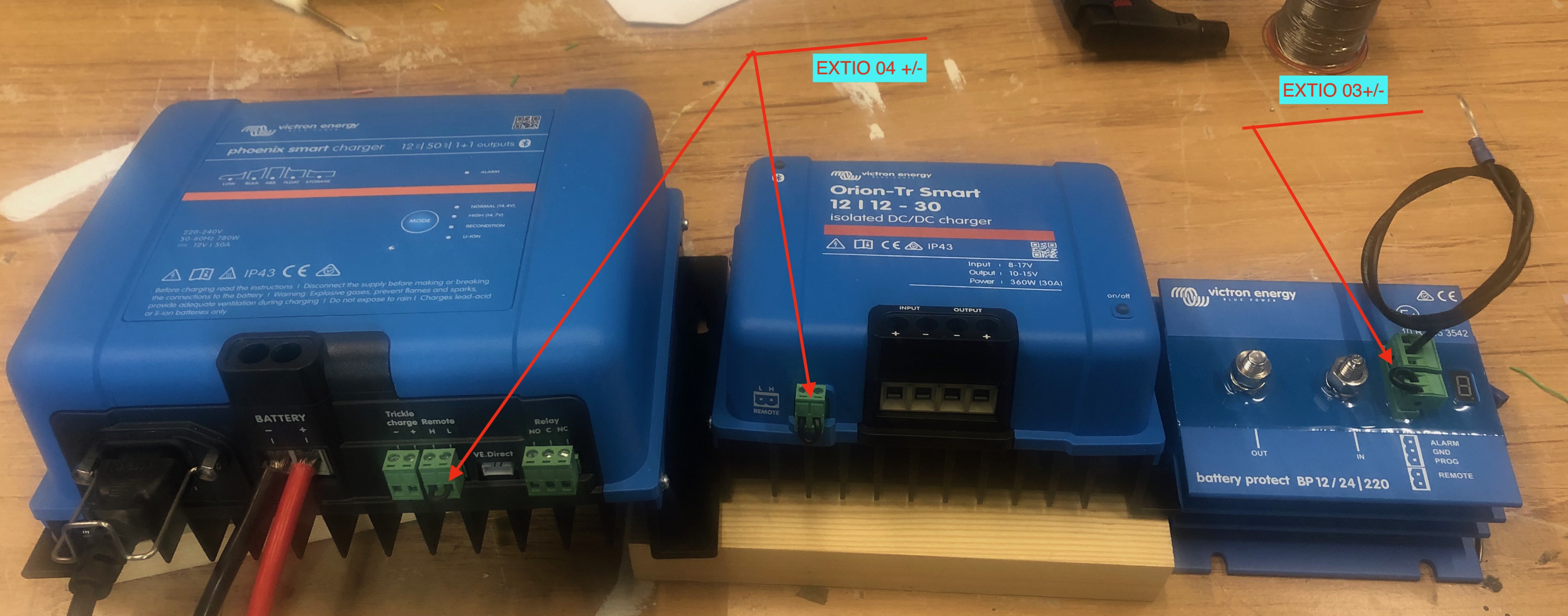

Dacian Todea
May 6, 2021, 4:57:28 PM5/6/21
to electrodacus
Henrik,
Not all victron devices have the same type of remote ON/OFF. For example the Multiplus inverter Aux inputs use 5V logic while other devices used battery voltage level as the ones you show.
Not sure if you can parallel the Orion and phoenix smart directly but what you can do in this case is connect EXT IO4+ to battery positive terminal through a 1kOhm resistor and then connect the EXT IO4- to H connection on the two devices and that will sure work.
Since the Battery Protect is just one device you can just connect it directly to EXT IO3 just need to take care of polarity with EXT IO3+ connected to L and EXT IO3- connected to H
Not sure which is H and which one is L on the BP220 as they have no real standard but to find out you just use a multimeter and see which one is positive and that will be the L (I know it seems confusing but L is pulled high with a pull up resistor internally and can be used as a remote by connecting that to GND) on the H is zero volt but if you connect there battery+ you can turn ON the BP220 so either L or H can be used as remote or both if you short them as the L will be pulled down by the H that will be supplied by the L :) So they sense both on L and H.
Dacian Todea
May 6, 2021, 6:50:35 PM5/6/21
to electrodacus
Henrik,
You cannot reply on forum through email.
Any 1/2W to 1W 1KOhm resistor will work fine should cost a few cents and you already have the connectors you just remove the short black wire and connect the EXT IOx- to the connection noted with H so you just use one of the two contacts on that remote connector.
Henrik Voldsgaard
May 9, 2021, 3:22:59 AM5/9/21
to electrodacus
Hi Dacian
Just another thought.
The ac- charger and the DC-DC will never be used at the same time. The DC-DC will only work with the engine where the DC-DC is activated by a connection to the ignition.
In harbour I will use the AC-charger when the engine is not running.
In fact they will not be paralleled will they? And will I then need a resistor?
In the rare situations where I will have to run the engine I harbour for service purposes, I can either de-connect the AC-shorepower or have a de-activation switch on the ignition connection to the DC-DC
What do you think?
Thank's
Henrik
Dacian Todea
May 9, 2021, 12:38:19 PM5/9/21
to electrodacus
Henrik,
The grid charger can use the EXT IO5 set as type 1 and have the EXT IO5+ connected to battery+ through a 1kOhm resistor and the EXT IO5- to the H pin or if you prefer you can in this case just connect the EXT IO5+ to the L pin and EXT IO5- to H pin no resistor will be needed unlike battery to battery charger where the ignition signal needs to be in series with SBMS0 EXT IOx as else you can overdischarge your starter battery if engine is not running.
Henrik Voldsgaard
May 16, 2021, 7:58:53 AM5/16/21
to electrodacus
Hi Dacian
Thanks for your advice and directions regarding connecting the SBMS0 to the grid charger and Orieon DC-DC.
You offered a few different options that I have drawn into the attached models 1 and 2. First, I would of course like an assessment of whether I have understood your instructions correctly? Secondly, I am interested in whether there is a difference in function between model 1 and model 2? Thirdly, I have an idea to mount a switch for the DC-DC (marked with '?') And I would like your assessment of whether SBMS0 can handle it in model 1, where 'ignition' is connected directly to SBMS0?
Thank's
Best regards
Henrik
Henrik Voldsgaard
May 16, 2021, 8:04:20 AM5/16/21
to electrodacus
Hi Dacian - now with attachment
Thanks for your advice and directions regarding connecting the SBMS0 to the grid charger and Orieon DC-DC.
You offered a few different options that I have drawn into the attached models 1 and 2. First, I would of course like an assessment of whether I have understood your instructions correctly? Secondly, I am interested in whether there is a difference in function between model 1 and model 2? Thirdly, I have an idea to mount a switch for the DC-DC (marked with '?') And I would like your assessment of whether SBMS0 can handle it in model 1, where 'ignition' is connected directly to SBMS0?
Thank's
Best regards
Henrik
Dacian Todea
May 16, 2021, 1:31:45 PM5/16/21
to electrodacus
Henrik,
I guess you created those in Microsoft version of powerpoint and I opened them in Libreoffice (as I'm in Linux) they look fairly bad should have posted as pdf but as far as I can see model 2 is OK is just about the ignition being used on EXT IO4 and using EXT IO5 to control the Orion.
On vers 3 not sure what is with the ignition signal as it seems connected wrongly but it may just be the Libreoffice interpretation of the .pptx file.
Henrik Voldsgaard
May 16, 2021, 2:03:39 PM5/16/21
to electrodacus
Hi Dacian
Sorry for the document format and for not being suffiently concentrated when making the drawing in model 2.
Will it be ok with a switch to DC-DC and how will SBMS0 react when you switch off at the same time as the ignition send a signal to the SBMS0 that the engine is running?
I will like to be able to switch the DC-DC off in case there is shore power and the motor is running for service.
PDF attached
Dacian Todea
May 16, 2021, 2:17:40 PM5/16/21
to electrodacus
Well it does not look hugely better :) The text is better scaled but I was thinking there was more wrong on the drawings. Like for example the EXT IO3 shows as if is connected to the two power terminals when it will connect to the two pin green connector on the BP220
Yes that model 2 is fine in therms of EXT IOx connections.
Henrik Voldsgaard
May 16, 2021, 2:40:20 PM5/16/21
to electrodacus
Thank's - I am aware of the connections for the Battery Protect :-)
Reply all
Reply to author
Forward
0 new messages