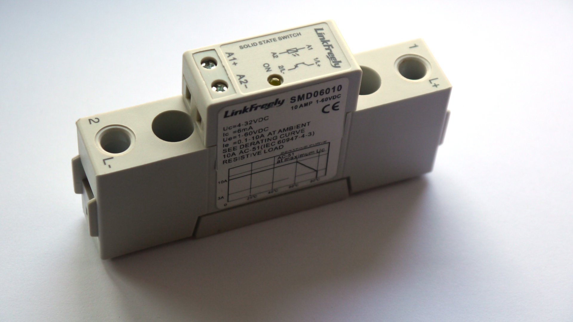
10A 60V Solid State Switch for EXT IOx expansion or maybe other uses.
119 views
Skip to first unread message

Dacian Todea
Aug 28, 2021, 8:31:39 PM8/28/21
to electrodacus
Some people have asked if there are alternative to the inexpensive optoisolator boards to extend the number of different devices controlled with EXT IOx.
Main complain about those boards seems to be the low quality connectors and maybe bad soldering on them or easy to break the solder point as you tighten the wire.
I recommended an inexpensive so called Solid State Switch (basically a solid state relay) with transformer isolation and a single mosfet on the output.
I will say the device seems to be according to spec and can handle the 10A rating without any problems or need for any heatsink and it is inexpensive as it can be had for around 10CAD (7USD) as the one I have and there is 1 or $2 more for the one that has the clamp to be installed on a DIN rail.
I just got one to test so that I can recommend and yes is not often when they work as advertised :) but this one is.
The power mosfet is a Sanyo 2SK3825 with 10 to 13mOhm but including PCB trace I measured around 15mOhm under full 10A load.
So if used at 10A total loss as heat will be 10A * 10A * 0.015Ohm = 1.5W and that is not a problem with passive cooling. Likely the higher rating ones I saw 25A and 40A are this exact one just installed on a heatsink. But those are more expensive and 10A is already way overkill to control remote ON/OFF on different devices.
You can even use it instead of Victron BP65 as long as you have a 10A fuse and you use it for mostly restive type loads not captive.
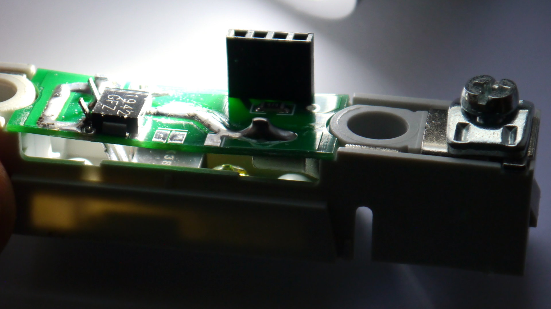
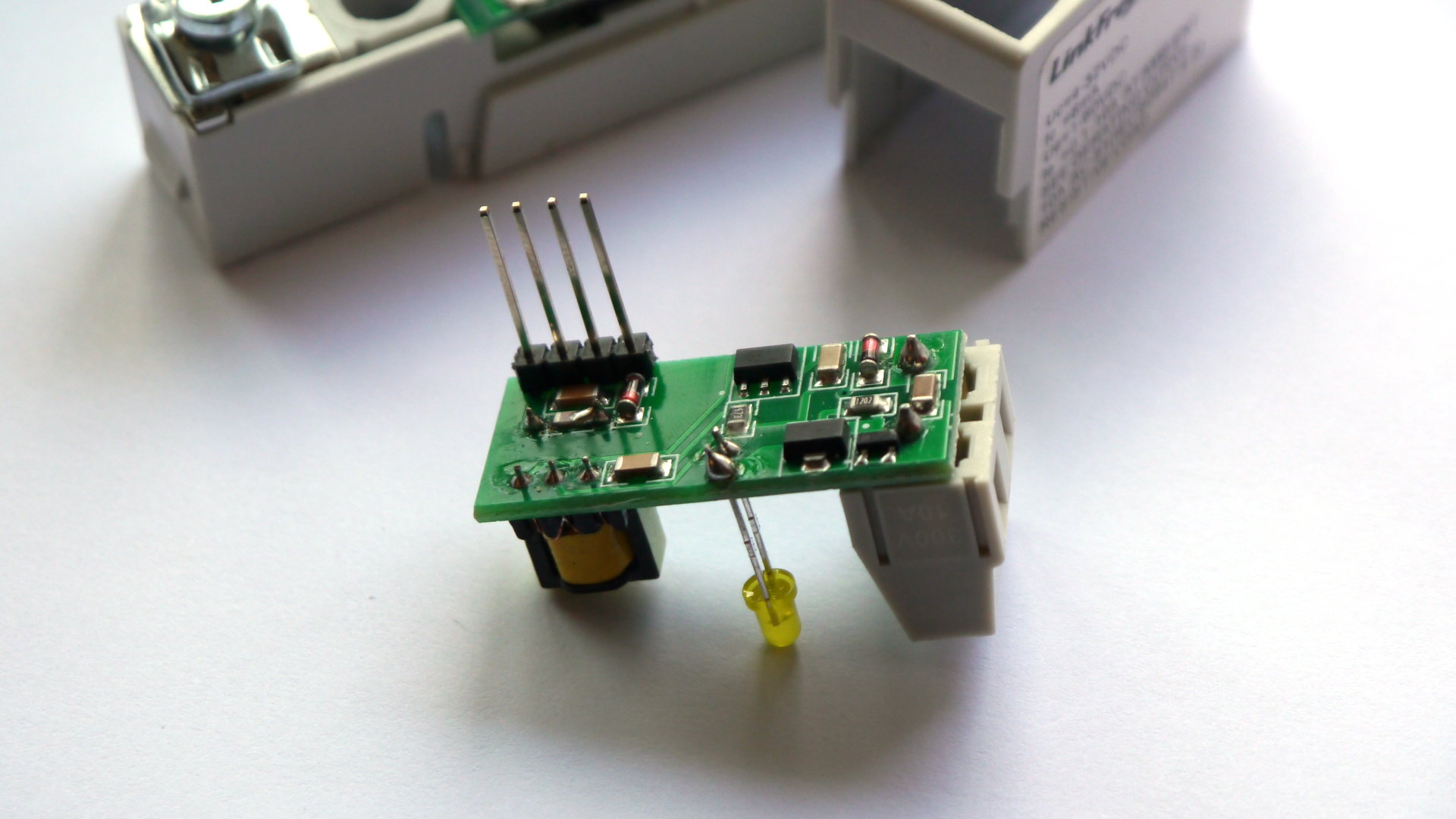
Bellow a few photos of the internal construction.
My unit. The input requires just 1 or 2mA depending on voltage and you need at least 5V as 4V is a bit to low and anything up to 32V is fine so you can just connect directy to battery trough EXT IOx in series with a resistor to protect wires and EXT IOx in case of a short circuit. You can have almost as many as you want of these in parallel controlled by one EXT IOx
Here is the bottom part only containing the mosfet I mentioned 2SK3825 (may be some sort of clone but it works as advertised so not relevant) a TVS 51V 1500W to protect from transients and a 470kOhm resistor plus the connectors that are soldered to same PCB.
And this is the part on top that connects to the power board trough the 4pin connector and this one contains the transformer for isolation a few transistors to do the switching for the transformer a 2 pin connector for control and a yellow LED as indicator.
Seems like a lot of manually soldered parts not sure how they can get to about $7 considering the effort.

Jim A
Aug 29, 2021, 10:18:38 AM8/29/21
to electrodacus
Dacian, Could this be used to isolate a Raspberry Pi from the UART connectors?
Dacian Todea
Aug 29, 2021, 1:27:23 PM8/29/21
to electrodacus
No, this will be way to slow for UART communication.
Jim A
Aug 29, 2021, 2:36:48 PM8/29/21
to electrodacus
Unfortunate, I still have not found anything 'off-the-shelf' and reliable that I can use with my SBMS120.
Dacian Todea
Aug 29, 2021, 3:26:21 PM8/29/21
to electrodacus
Most ready made isolators are for USB to UART not UART to UART as most modern computers have USB but do not have a UART or a RS232
Of course that USB to UART isolator will contain a USB to UART IC and then a UART to UART isolator and you want just that other half as a separate board.
It will be fairly easy to build one but not sure if there is one you can buy on a board with connectors.
Here is a schematic using the 6N137 https://electronics.stackexchange.com/questions/317622/how-to-get-3-3v-output-from-vishay-6n137-high-speed-opto-coupler
All it needs is two 470Ohm resistors one on the input on pin 2 then the other side of the resistor connects to SBMS TX pin and the pin 3 connects to GND
While in that diagram it shows a 4.7K resistor you will need to ause a 470Ohm so you need that 6N137 and two 470Ohm resistors plus a 100nF capacitor.
Reply all
Reply to author
Forward
0 new messages