MPS-V Plus 3.5kW inverter
2,128 views
Skip to first unread message

Dacian Todea
Jun 21, 2021, 11:49:36 PM6/21/21
to electrodacus
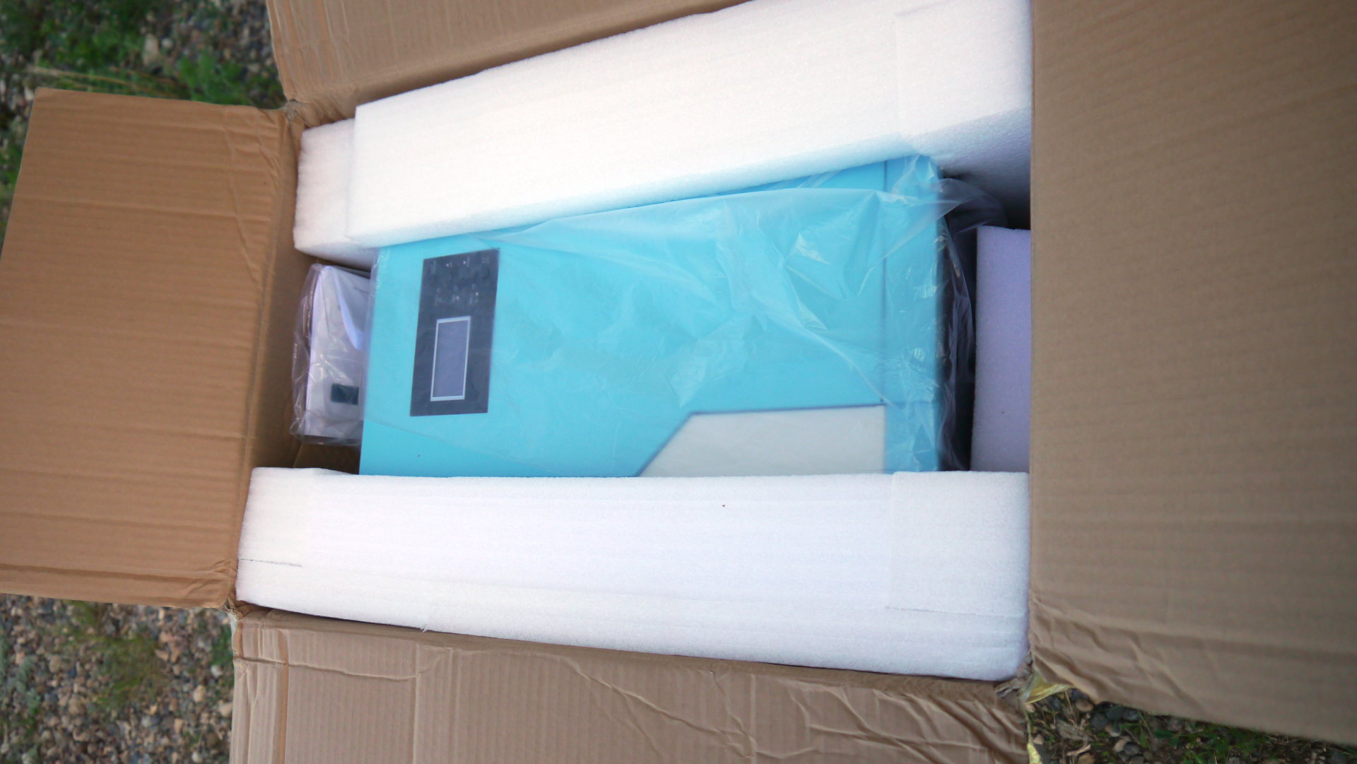
Just got this inverter and took a few photos. I looked for some time for a low cost quality inverter that I can recommend.
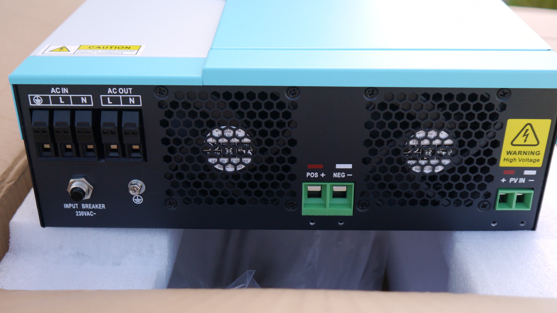
The two down sides of this inverter is the relatively high self consumption 43W (measured as spec says 35W) and it only comes as a 230V AC version (not a problem for those outside North America).
All other things seems to be positive including the very low price and excellent build quality plus excellent spec mostly the 10 second for up to 150% overload and 5 seconds for up to 200% overload (that is 10x more than most other inverters).
I do need to test this claims but I have no reason not to think this are real.
I have a fairly similar inverter from MPP Solar for almost 5 years of daily use and it performs great tho this is a 2.4kW version so smaller and a different brand but similar design.
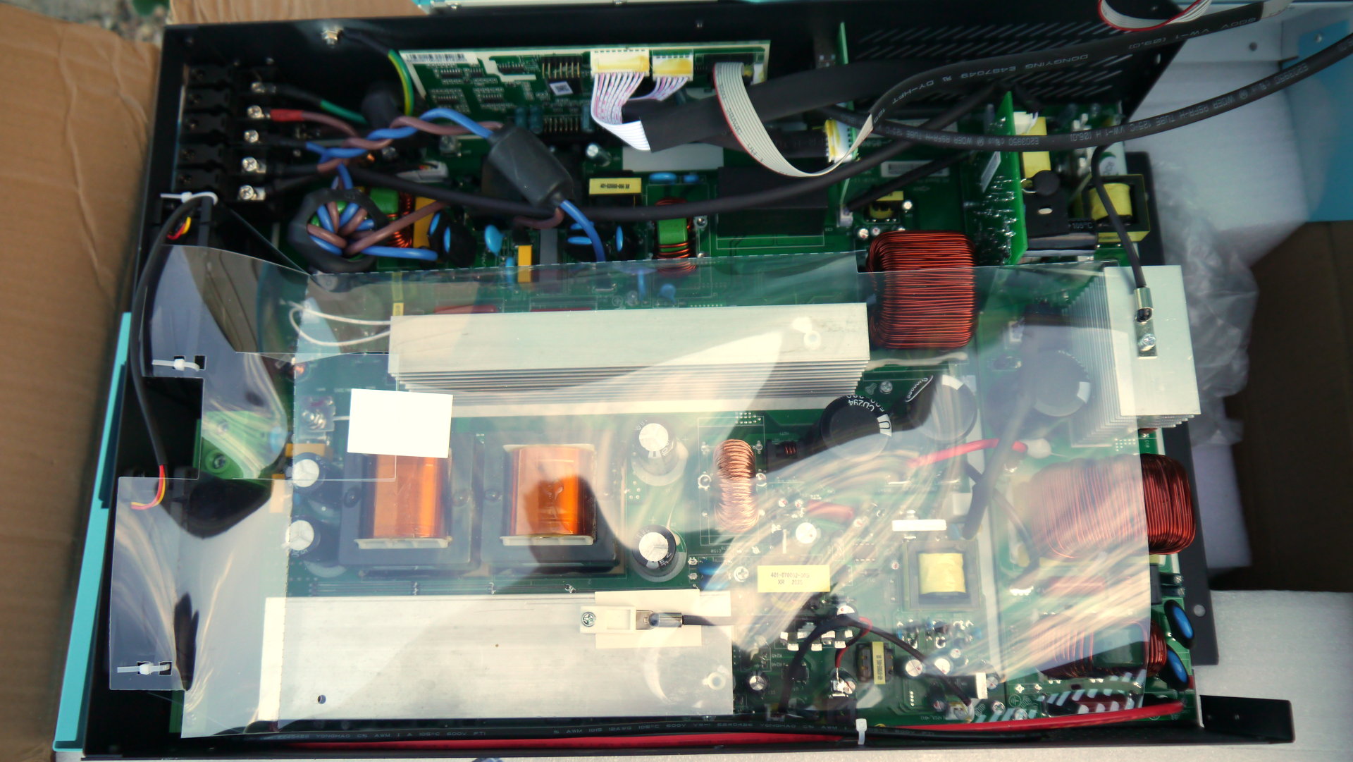
By looking at the internal construction the design seems to be a large step UP DC-DC converter (bidirectional to also be used as a charger) probably making around 400Vdc then from that they make the 230Vac
And there is also an MPPT but that is also a step up and requires at least 120V max power point voltage at the input so they recommend minimum 5 panels in series and the output of that will also be around 400V and it will parallel with the DC-DC converter connected to battery then from that the 230V AC is made.
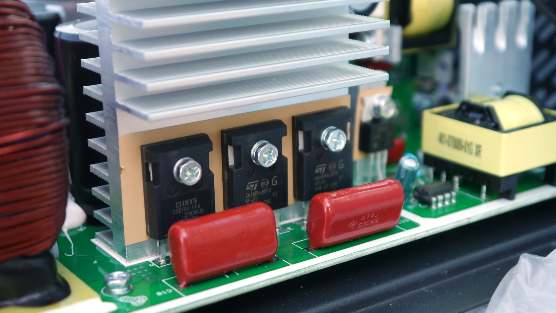
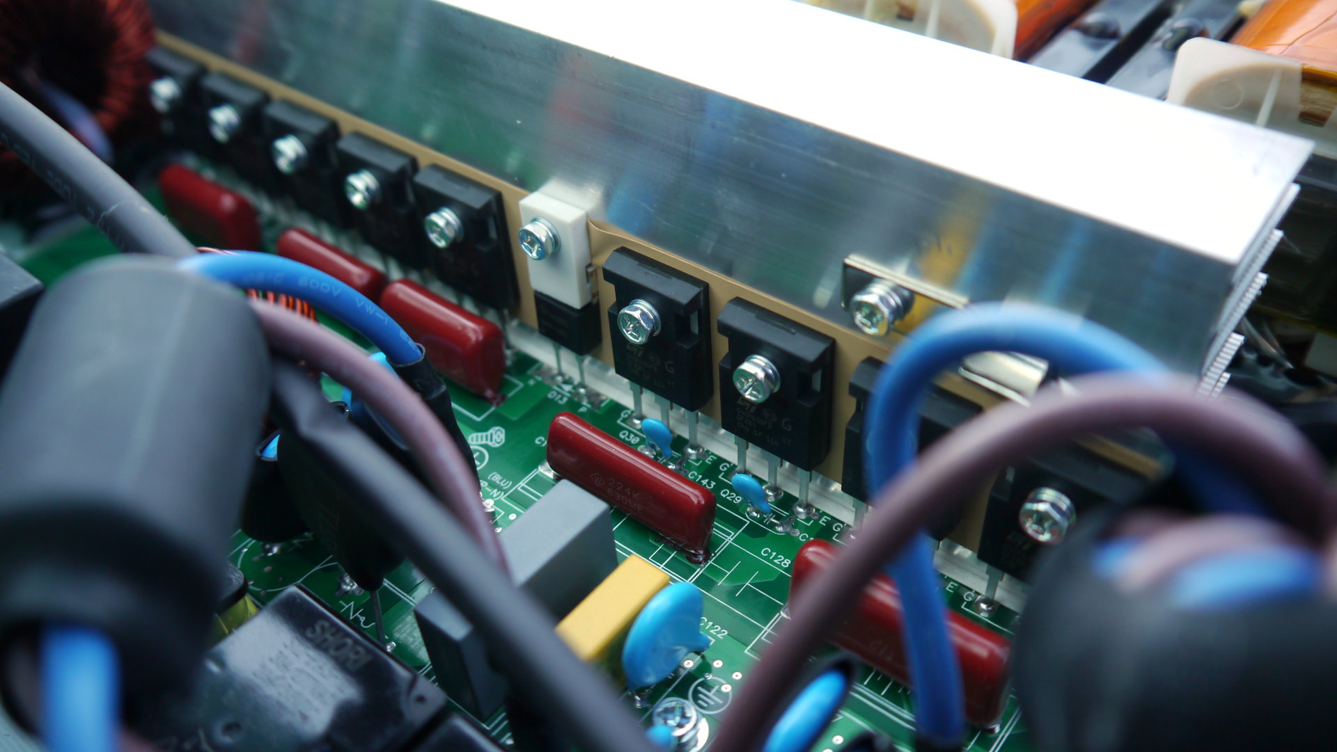
It seems they are using ST IGBT transistors everywhere 650V rated different models.
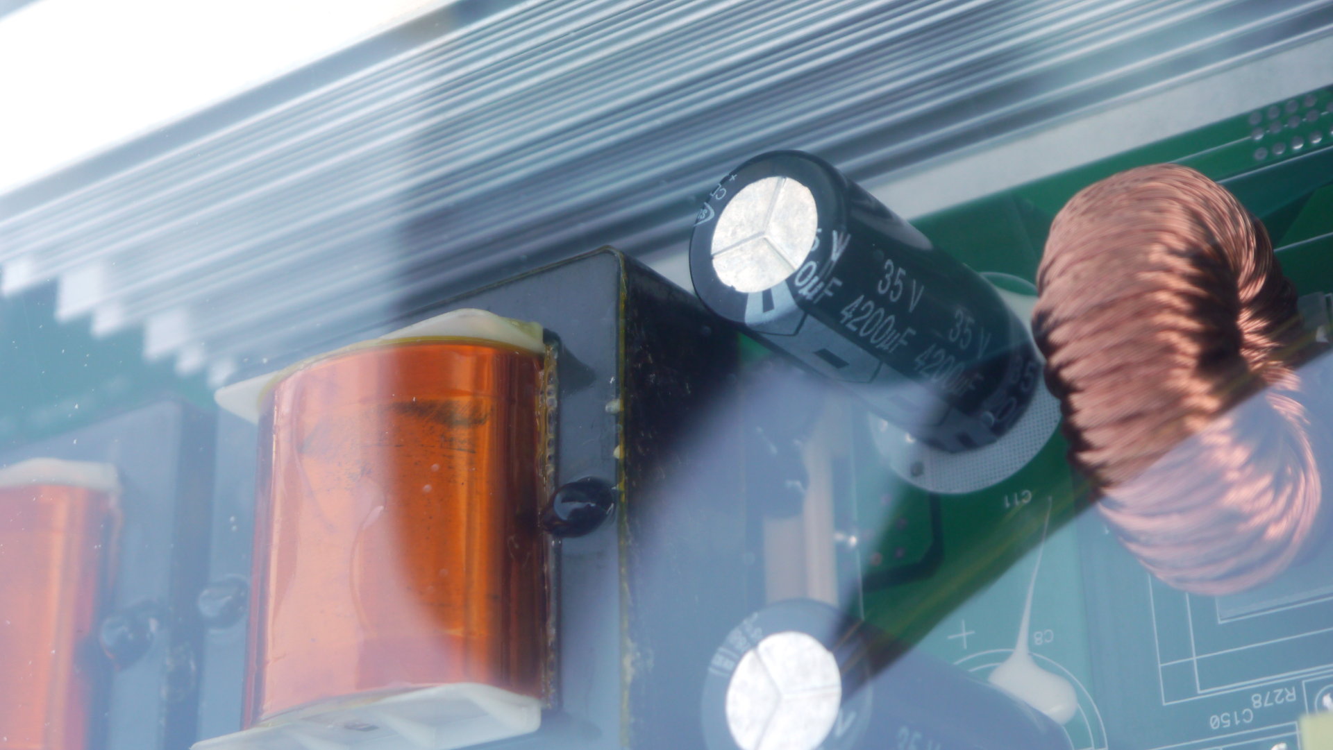
The DC-DC on the battery side has two transformers so there are likely two parallel circuits and there are 4 input capacitors 4200uF at 35V for this 24V version guessing they will have 63V rated capacitors for the 48V version of this inverter.
The limiting factor for continuous use is the input connector that is only 125A rated tho installed between two fans so should at least be able to handle what they claim 162A for some minutes and same with the 150A rated fuse that is cooled by the fans so maybe it will be fine.
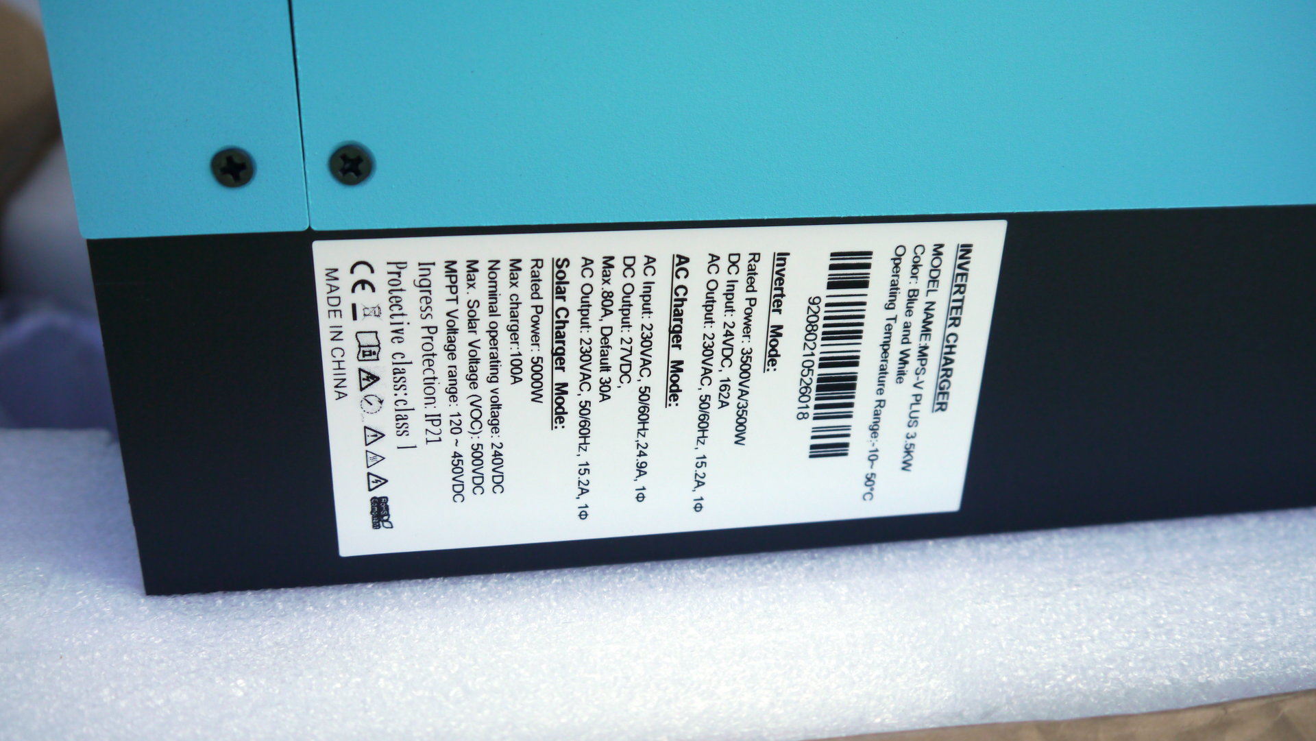
Now a 8s LiFePO4 is almost always above 26V and assuming that 26V x 162A = 4212W on input side but if we consider the connector 125A limit (much more conservative) then is 3250W on DC side that will correspond to 3022W on AC side assuming that spec peak efficiency of 93% (I will test this).
Here is the seller I purchased this from but there are many others https://www.aliexpress.com/item/4000171107997.html
Looks like now is at 410CAD (I can see the price in CAD as I'm in Canada) + 168CAD shipping but I paid 158CAD shipping so in total I see I paid 567CAD whatever that converted in USD at that time.
Shipping was fairly fast with FedEx I just needed to pickup from airport as they can not deliver to PO Box.
In any case just under 600CAD delivered is an excellent price. I also ordered from Mouser a 2500W isolation transformer so I can convert 230V in to 115V but this is a bit of a different story. I now have a 1000W isolation transformer with the current 2400W inverter and so I can supply loads of up to 2000W as long as average over long period is below 1000W all is fine.
And 2000W is my max load for one of the ovens so I do not need more but I got this to test and be able to recommend to others.
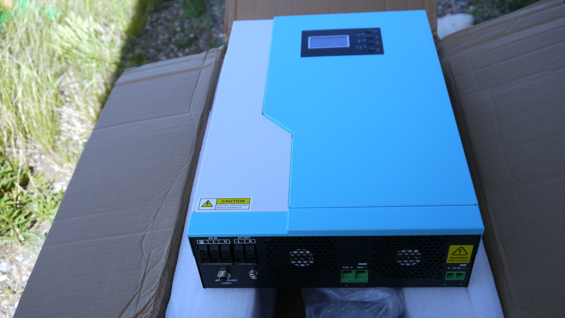
A few photos I took just after I opened the box. It will take some time before I receive the transformer and maybe the batteries and then I will do more tests and compare to my current inverter. But first impressions are very good.
Forgot about the color (not a big fan of blue but not that relevant :) )
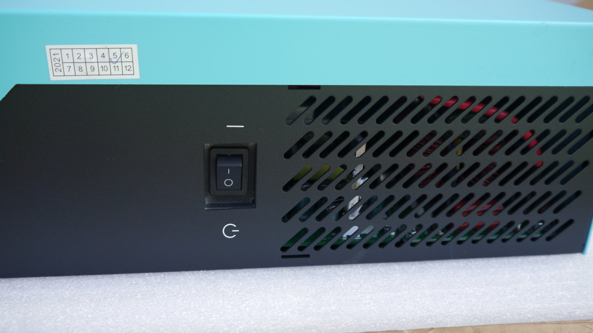
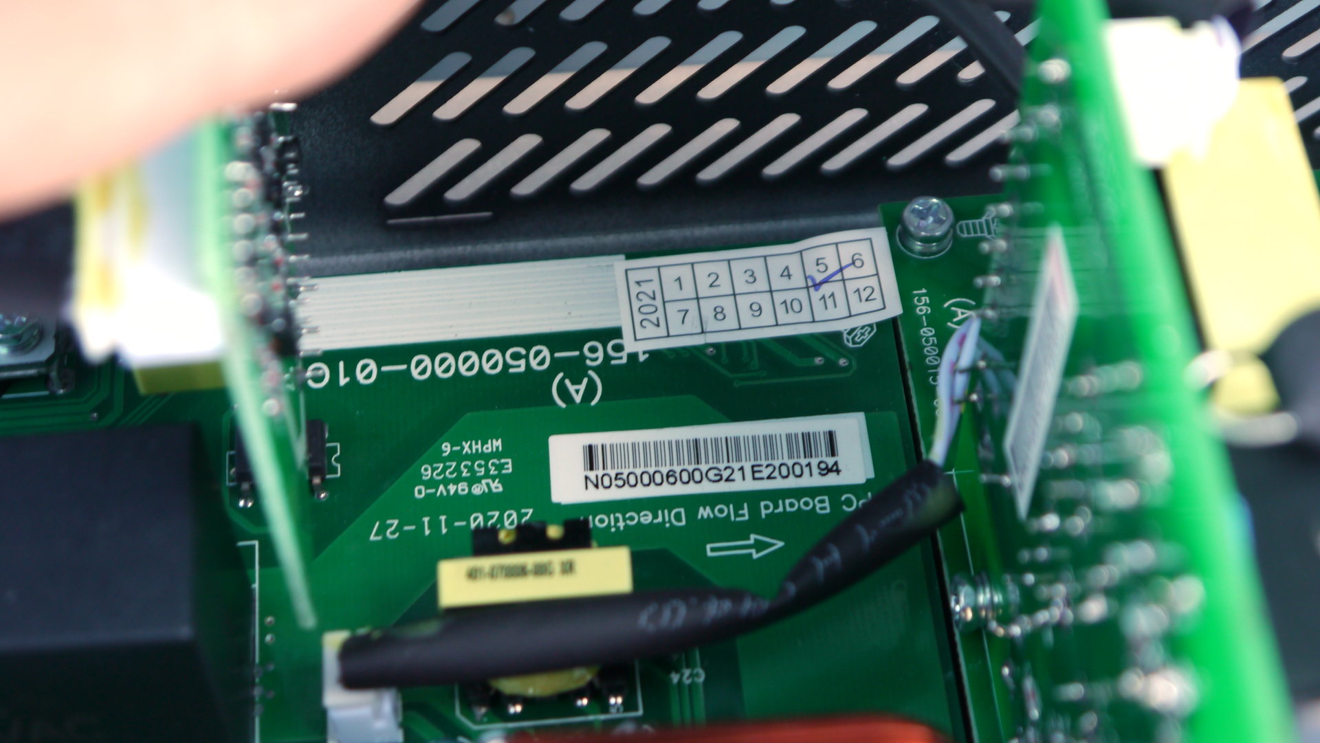
Look at manufacturing date is fresh from factory :)
There are two PCB's the large one on the Left contains the battery DC-DC converter includes the two large transformers at the bottom and the top part is the high voltage DC to AC conversion plus the UPS part with the 3 relays.
Then the smaller PCB on the right is the MPPT converter and there are two wires paralleling the two high voltage busses.
The two ST branded IGBT for the MPPT and an IXYS branded diode.
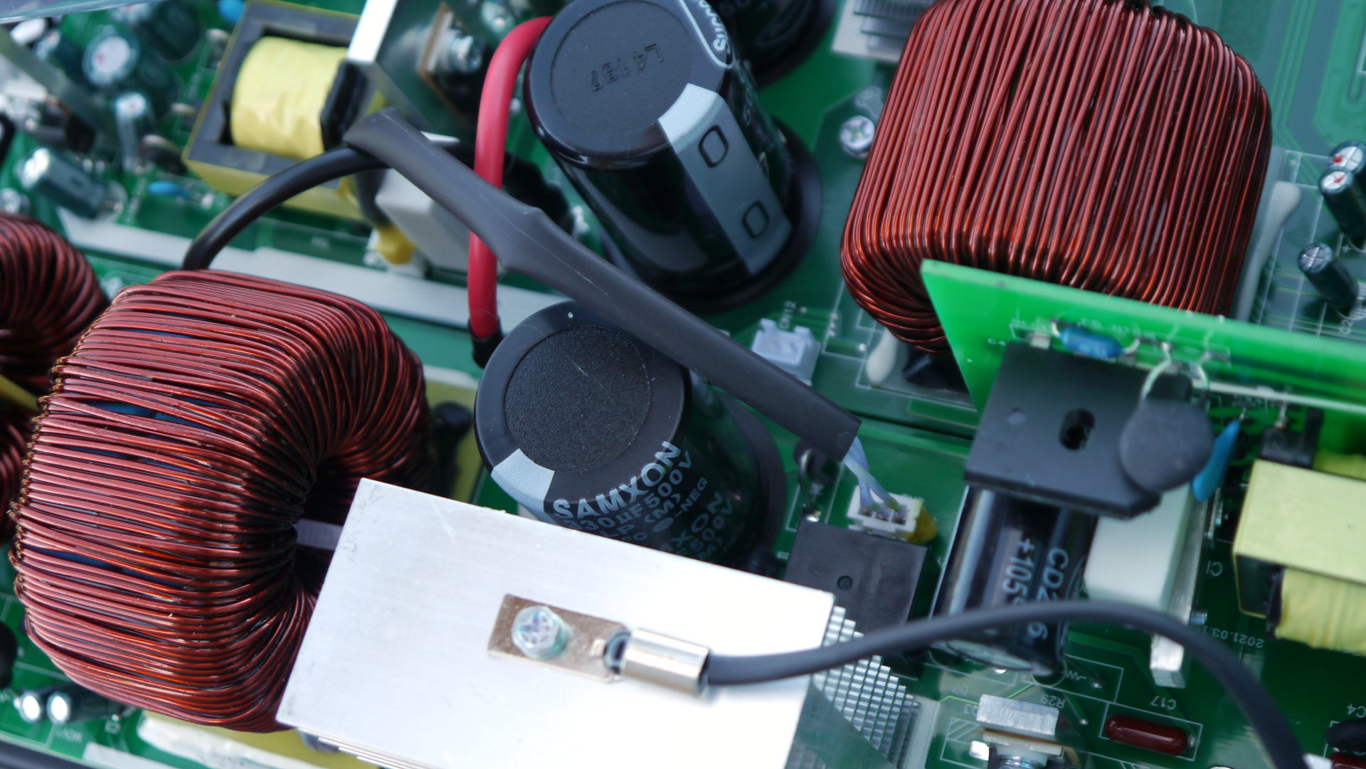
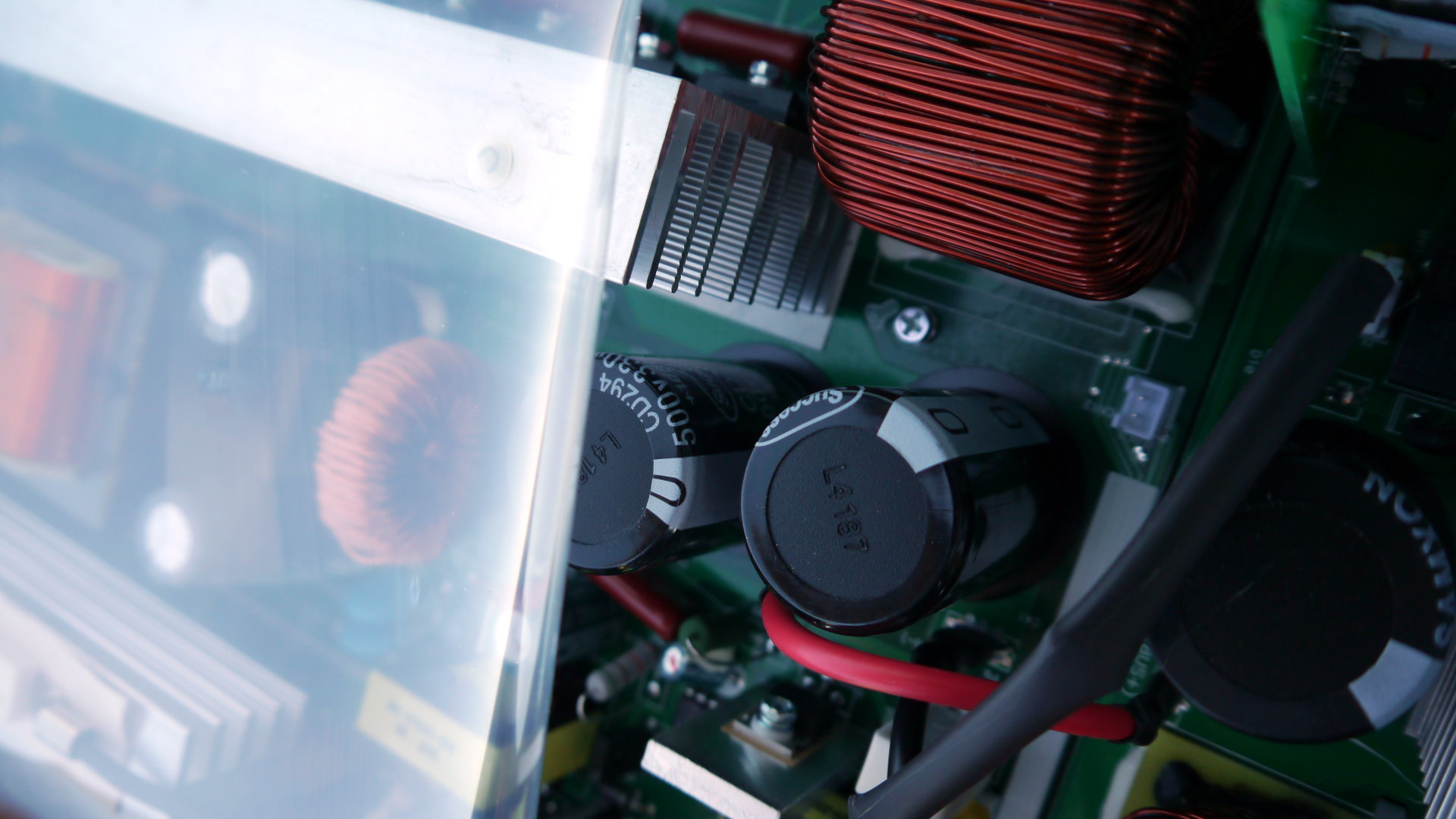
The 330uF 500V rated capacitor on the MPPT output. Notice the red and black wires going to the inverter high voltage side.
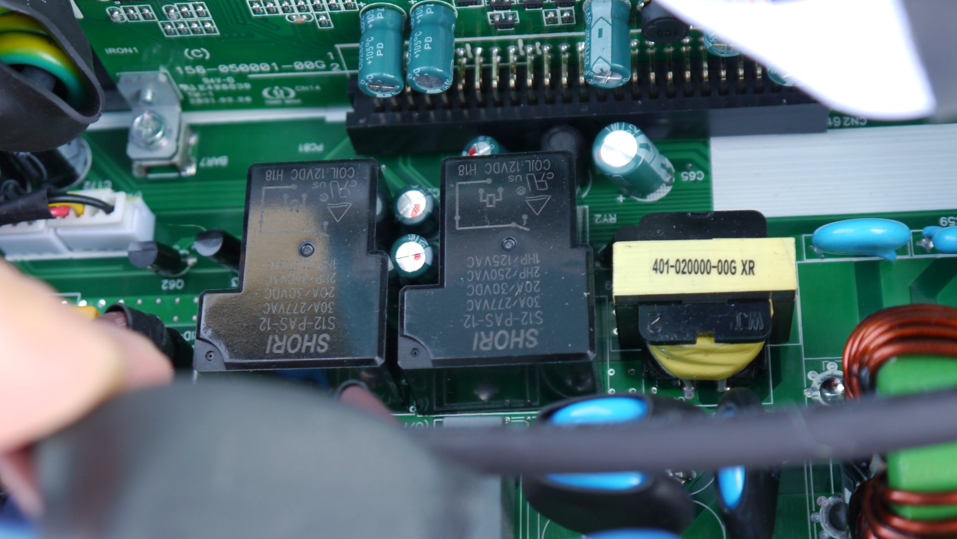
Two of the AC bypass relay. There is a third one not in the photo.
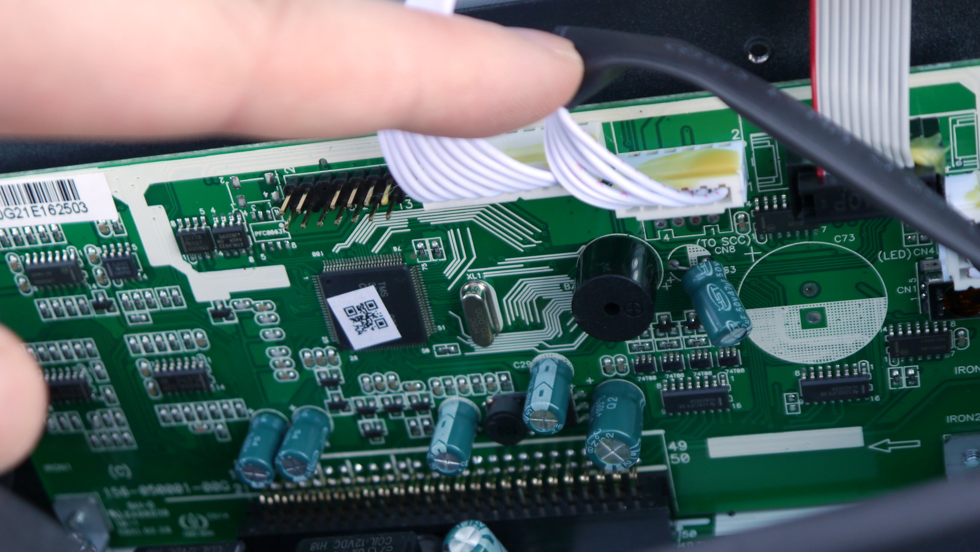
Main control board.
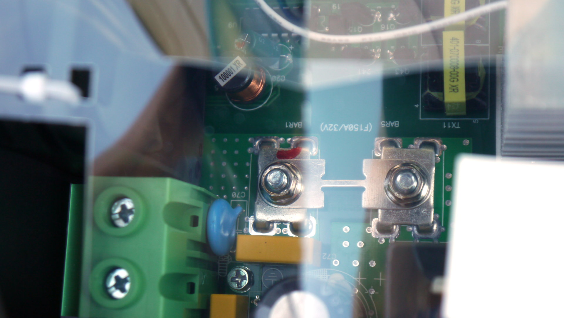
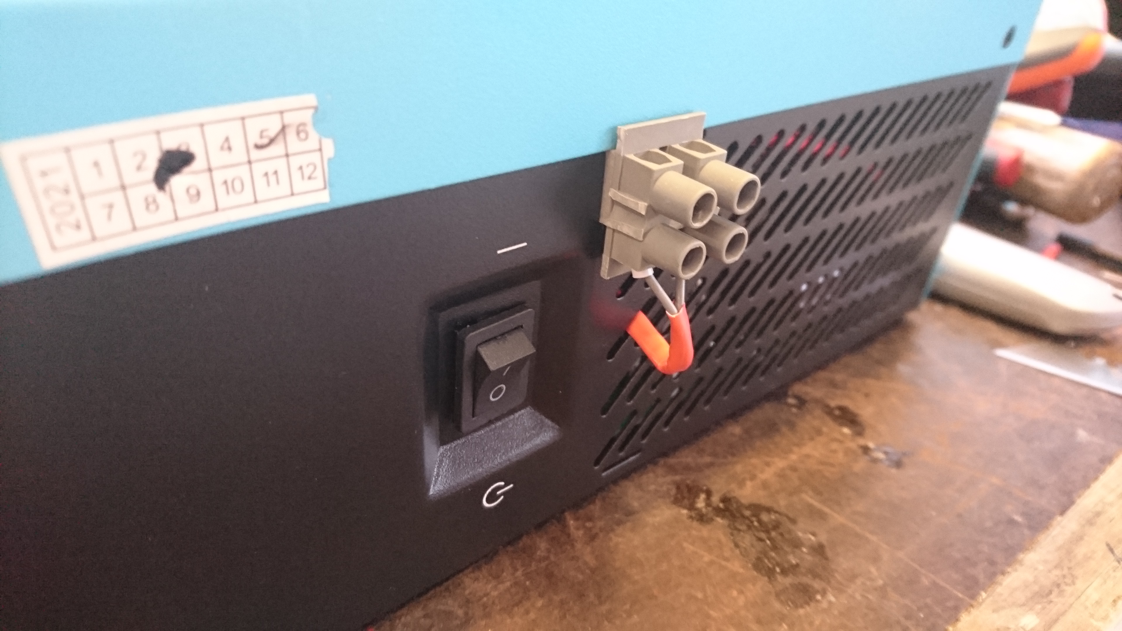
The 125A rated battery DC connector and the 150A fuse. There was a spare fuse in the box but hopefully will never be needed it seems to have 0.2mOhm
The input capacitors 4200uF 35V two next to each transformer so 4 of them in total.
The two 330uF 500V capacitors on the DC-DC output side. I will need to measure what voltage they have here but I guess it is around 400V maybe even 450V so do not play inside this inverter and actually any other inverter :)
Again manufacturing date just last month and even board design date is late last year.
IGBT for the AC side also from ST just a different model than those on the MPPT.

Plamen
Jul 3, 2021, 4:56:44 AM7/3/21
to electrodacus
Hi Dacian.
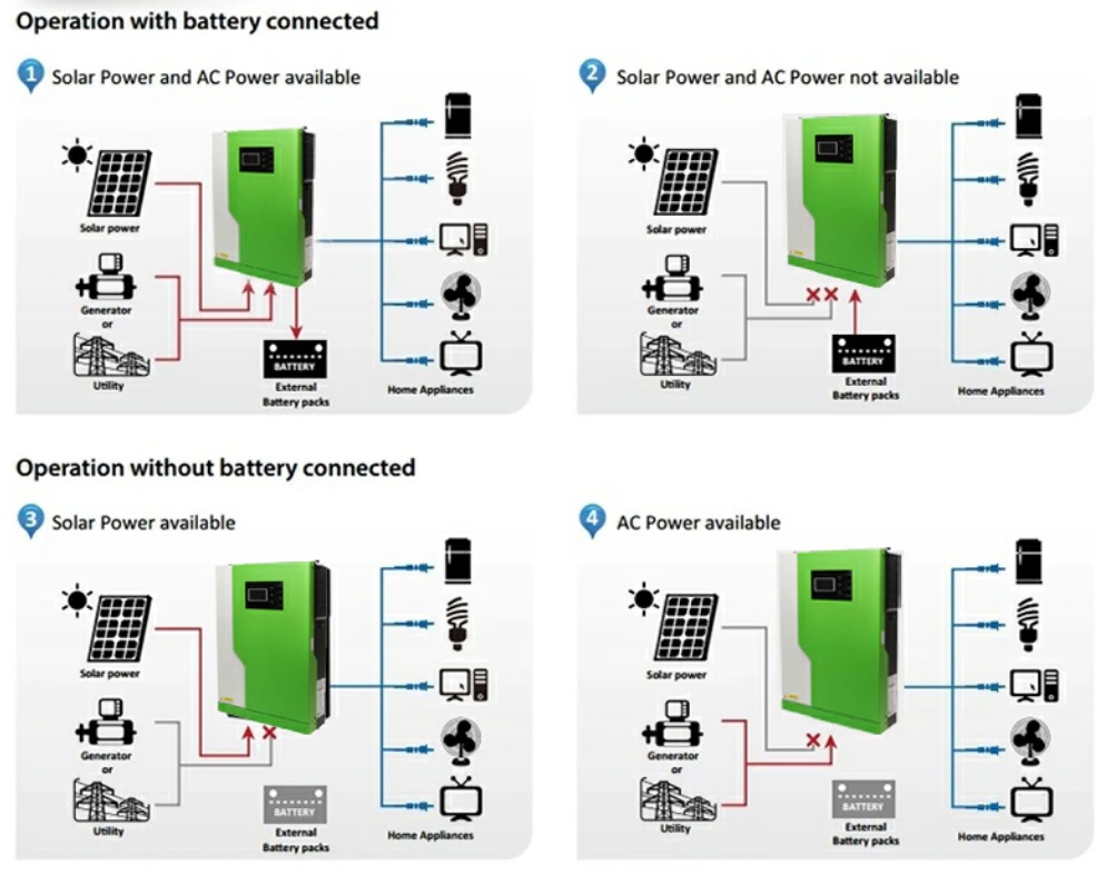
Is it true that it also works without a battery, only with photovoltaic?
Plamen
Jul 3, 2021, 5:01:42 AM7/3/21
to electrodacus
Dacian Todea
Jul 3, 2021, 5:04:42 AM7/3/21
to electrodacus
Yes it is true but also useless.
Your load will always need to be below what solar panels produce.
Say you get 3kW from the panels at some specific point then your max load needs to be below about 2.5kW (there are some conversion losses).
If you try to turn ON a load that needs more than that the entire system will shunt down and reset as there is no battery to provide the difference.
Any small cloud will power off all your loads. Also your fridge start up current if higher than what PV array can provide at the time will power off the inverter.
This is not an intentional useful future just an accident of the design.
This is not an intentional useful future just an accident of the design.
Plamen
Jul 3, 2021, 5:26:38 AM7/3/21
to electrodacus
It only has main on/off switch. I was thinking if it can be used for charging from a PV that is at a bigger distance. If that 500v. open voltage is useful, then the charging should be controlled by a SS switch that disconnects the PV line. Or You recommend it only as inverter.
Dacian Todea
Jul 3, 2021, 12:18:41 PM7/3/21
to electrodacus
You can try and find a 600 or 650V DC SSR to connect on the input and I will not recommed more than 10x 60 cell panels in series despite what manufacturer claims as that MPPT solar charger is just a step up DC-DC converter so it can not reduce the PV input voltage it can only bust that from at least 120V so you need at least 4 probably 5x 60 cell panels and no more than 10 panels at the input and then a SSR capable of handling that or maybe it will be better if you can find the ON/OFF control circuit inside so no extra device is needed. I can not find that out and then recommend doing that since this are very high voltages we are taking about and you know I do not like anything above the safe 60Vdc open circuit voltage.
Plamen
Jul 3, 2021, 2:25:23 PM7/3/21
to electrodacus
I don't have that inverter but if i'll make another PV array as carport in the future this one may be a good choice.
Thanks!

Leon Close
Jul 12, 2021, 3:59:13 AM7/12/21
to electrodacus
To control this inverter with the SBMS0, is it possible to use the communication ports somehow? Or is it necessary to tap in to the power switch?
Dacian Todea
Jul 12, 2021, 8:28:44 PM7/12/21
to electrodacus
Only the power switch can be used. The proprietary serial communication even if not proprietary will not be useful as inverter will need to be ON for this to work so that way the inverter can not be fully turned OFF and self consumption alone is large and will discharge the battery without the SBMS being able to do anything. With the power switch if any cell is to low 2.8V the SBMS can fully turn OFF the inverter and there will only be less than 1W because of the SBMS
Leon Close
Jul 12, 2021, 8:42:54 PM7/12/21
to electrodacus
Thanks, that makes sense.

Steve Marotta
Jul 17, 2021, 6:26:02 AM7/17/21
to electrodacus
Hi Dacian,
Would the AC charge function on this unit be able to be utilised with an SBMS0?
If so how would it be controlled? In my proposed use case it would be the connection of a backup AC 230v generator in case of bad weather and minimal solar production.
Thanks
Plamen
Jul 17, 2021, 7:50:45 AM7/17/21
to electrodacus
Hi Steve, You could wire a Solid state relay on the AC 230V side of the inverter or in your case maybe even better to connect SBMS0 in series withe the generator on/off switch. This way when battery is charged not only the charging but your gen. will also stop.
Plamen
Jul 17, 2021, 7:55:14 AM7/17/21
to electrodacus
Downside is that if you have situation where your battery is completely discharged you should manually override the SBMS0 and start the inverter so the charging can start too. Hopefully you'll never get there.
Dacian Todea
Jul 17, 2021, 11:42:22 AM7/17/21
to electrodacus
No this can not be controlled directly by the SBMS0 but if all you need is some occasional charging from generator when your battery is low then you can have a SSR on the AC input line and have the SBMS0 control that.
Maybe what Plamen mentioned can also work but have no idea of the type of generator and you will not want the generator to start every time the battery needs charging.
Is best to avoid using a generator as that energy is super expensive when compared to solar and even with grid.
Plamen
Jul 17, 2021, 11:57:18 AM7/17/21
to electrodacus
I imagined that it's a manual start generator that is started by pulling a cord. Then SBMS will only can stop the gen. but not start it.
Dacian Todea
Jul 17, 2021, 11:59:15 AM7/17/21
to electrodacus
Plamen,
That may work then. I'm not familiar with generators as I never owned one.
Plamen
Jul 17, 2021, 12:03:23 PM7/17/21
to electrodacus
I know :-) Lucky you!
Leon Close
Jul 18, 2021, 7:10:59 AM7/18/21
to electrodacus
Having wired this connector to the main switch, is it ok to run a twisted pair directly to the EXTIO3+ and
EXTIO3-? I have not tested current in the inverter's switching circuit, I guess it is less than the 50mA the SBMS0 can handle but am not sure.
Dacian Todea
Jul 18, 2021, 12:27:34 PM7/18/21
to electrodacus
I did not had the time to test anything on the inverter but based on the old inverter current there is less than 10mA so yes you can connect directly to EXT IO3.
Leon Close
Jul 19, 2021, 1:36:39 AM7/19/21
to electrodacus
Thanks. I might try and make a measurement anyway, just so we know for certain.

Sasa Duric
Feb 18, 2026, 11:27:58 AMFeb 18
to electrodacus
Not sure are these inverter variants are all the same, but I here is my problem...
Should I tie PE+N with a switch? And, how? I am planing to use switch over for my camper to shose from the grid/inverter to supply my camper, and I thought first to use third contact of Hager SFT340 switchover to bridge PE+N when in the inverter position and have it off when in the grid position, but the inverter also floats when connected to the grid, just the voltages are bit different. What would be proper and safe way to do it?
I wanted to add RCBP to it's output, but it have floating Ground so it won't work properly.
These are measured voltages offgrid and connected to the grid:
offgrid
PE-N 72V
PE-L 180V
PE-L 180V
tied to grid
PE-N 126V
PE-L 113V
PE-N 126V
PE-L 113V
Should I tie PE+N with a switch? And, how? I am planing to use switch over for my camper to shose from the grid/inverter to supply my camper, and I thought first to use third contact of Hager SFT340 switchover to bridge PE+N when in the inverter position and have it off when in the grid position, but the inverter also floats when connected to the grid, just the voltages are bit different. What would be proper and safe way to do it?
Sasa Duric
Feb 18, 2026, 11:31:17 AMFeb 18
to electrodacus
I meant RCCB. It seams no edit is possible
Dacian Todea (electrodacus)
Feb 18, 2026, 1:15:59 PMFeb 18
to electrodacus
Yes all inverters are like this.
I'm fully offgrid all the time and my house is always fully isolated (no ground connection). I even use a transformer on the output of my inverters since these are 230Vac output and I use 115V here in Canada.
If you want to connect PE+N that should be only when you are not grid connected. The camp site most likely has his own RCCB and that will trip if you have the PE+N bridged on your side.
To me it sounds correct to use the third contact on that transfer switch to bridge the PE+N when on the inverter and disconnected while switched to grid but I did not think at all possible scenario and I do not know your full installation. I do not work with earth ground in my setup so maybe I'm not the best to answer this. Maybe one of the other forum users has a similar setup and can better answer.
Not quite sure why you need a transfer switch. I was thinking you just connect the inverter input to the grid and you loads are always supplied from inverter output. Inverter acts as a UPS/ transfer switch.
Sasa Duric
Feb 19, 2026, 11:10:14 AMFeb 19
to electrodacus
Don't you have RCCB in your system? Or you have one of those that work in floating systems?
I have read it is not ideal and can be problematic with some devices. I suspect my fridge is broken as I run it on the floating supply the whole year, and I have noticed induction cooktop have some buzzing noice when that i do not hear when it is on the grid. I have checked the signal, and it looks proper sinusoidal and have 50Hz. That was with my other FCHAO 1.8kW inverter.
I wanted to avoid using this invertor as my only main 230V source for a few reasons. One of it is because of the noise. It is very, very loud to have it in the living area. And, I wanted to be able to quickly switch to a grid when parket at home and stationary.
Dacian Todea (electrodacus)
Feb 19, 2026, 11:53:12 AMFeb 19
to electrodacus
My system is not grounded so an RCCB will not work or be needed.
The buzzing has to do with how clean the sine wave from your inverter is not the fact that it is floating. Likely the induction counter top does not even have a metal case so no earthing connection anyway.
Without a load the sine may look perfectly fine but under load particularly a ugly load like an induction cook-top the inverter will not be able to respond that fast in correcting the voltage.
The noise of the inverter is real. My inverter is mostly off and only turned on a few hours a day when it is needed mostly for cooking. During the night is always off. Most of my loads lights, fridge, computers are powered from 24Vdc directly.
I did not think you needed any energy while parked at home.
Sasa Duric
Feb 19, 2026, 12:04:10 PMFeb 19
to electrodacus
I didn't new that. I need to hook this new one on the scope under the load and recheck. Thanks for the tip.
BTW. is your fridge DC?
Dacian Todea (electrodacus)
Feb 19, 2026, 12:14:22 PMFeb 19
to electrodacus
Yes the fridge is 12V/24Vdc mine runs at 24V directly from battery. Here are a few photos and power consumption numbers for the fridge https://groups.google.com/g/electrodacus/c/5nuUDAxD_ps/m/q2lyjt14AgAJ

Max Theiss
Mar 23, 2026, 9:49:00 AMMar 23
to electrodacus

Dacian Todea (electrodacus)
Mar 23, 2026, 9:45:08 PMMar 23
to electrodacus
This exists for some time. I do not see that much of a difference. It is the same design maybe with some small incremental improvements.
They have a 3.6 and 4.2kVA instead of the one I have 3.5kVA
And they are manufactured by many brands and each one wants to differentiate himself from others. Mine works every day for the past few years with no issues.
Reply all
Reply to author
Forward
0 new messages