Three phase induction motor
jo...@anelectricmotor.com

Three phase induction motor
Three phase induction motor
- Three-phase squirrel-cage induction motor
- Induction motor construction
- Working principle of a three-phase motor
- AC motor slip
- Induction motor connection
- Three phase alternating current
- Star and delta
- Terminals marking
- Using single phase power supply
- Induction motor control
- Direct-on-line starting
- Soft start
- Speed control
- Three-Phase Wound Rotor Motor
- Construction features
- Marking of rotor terminals
- Starting of WRIM
- Induction motor construction
- Working principle of a three-phase motor
- AC motor slip
- Three phase alternating current
- Star and delta
- Terminals marking
- Using single phase power supply
- Direct-on-line starting
- Soft start
- Speed control
- Construction features
- Marking of rotor terminals
- Starting of WRIM
Three-phase induction motor – is an asynchronous electric motor, that has a three-phase stator winding.
Three-phase squirrel-cage induction motor
A squirrel-cage induction motor (SCIM) – is an asynchronous electric motor, in which the rotor is made with a short-circuited winding in the form of a squirrel cage [1].
Induction motor construction
The three-phase induction electric motor, as well as any electric motor, consists of two main parts – the stator and the rotor. The stator is a stationary part, the rotor is a rotating part. Usually, the rotor is located inside the stator. There is a small distance between the rotor and the stator, called an air gap, typically 0.5–2 mm.

Induction motor stator
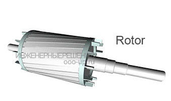
Induction motor rotor
The stator consists of an outer frame and a core with windings. The stator core is assembled from thin-sheet technical steel, usually 0.5 mm thick, covered with insulating varnish. Stator core laminations significantly limit the losses (eddy currents losses) arising in the process of magnetic reversal of the core by a rotating magnetic field. The stator windings are located in the slots of the core.
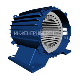 Frame and stator core of an induction motor
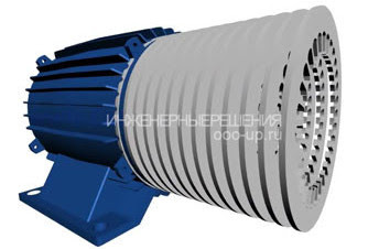
The construction of the laminated core of the induction motor
The rotor consists of a core with a short-circuited winding and a shaft. The rotor core also has a laminated construction. In this case, the rotor core sheets are not varnished, since the current has a small frequency and the oxide film is sufficient to limit the eddy currents.
Working principle of a three-phase induction motor. Rotating magnetic field
The principle of operation of a three-phase induction motor is based on the ability of a three-phase winding to create a rotating magnetic field when it is connected to a three-phase electric power system.
Rotating magnetic field – is the basic concept of electric motors and generators.

Rotating magnetic field of an induction motor
The frequency of rotation of this field or synchronous frequency of rotation is directly proportional to the frequency of the alternating current f1 and inversely proportional to the number of pairs of poles p of the three-phase winding.
- where n1 – the frequency of the stator rotating magnetic field, rpm,
- f1 – frequency of alternating current, Hz,
- p – the number of pole pairs.
The concept of a rotating magnetic field
To understand the phenomenon of a rotating magnetic field better, consider a simplified three-phase winding with three turns. The current flowing through the conductor creates a magnetic field around it. The figure below shows the field created by a three-phase alternating current at a particular point in time.

Magnetic field of the conductor with direct current
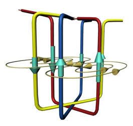 Magnetic field produced by a windings current
The components of the alternating current will change with time, as a result of which the magnetic field created by them will change. In this case, the resulting magnetic field of the three-phase winding will assume a different orientation, while maintaining the same amplitude.

Rotating magnetic field
Action of a rotating magnetic field on a closed conductor
Now we place the closed conductor inside the rotating magnetic field. According to the Faraday’s law of induction, a changing of the magnetic field will lead to the appearance of an electromotive force (EMF) in the conductor. In turn, the EMF will produce a current in the conductor. Thus, in a magnetic field there will be a closed conductor with a current on which force will act, according to Ampere’s law. As a result of which the loop will begin to rotate.
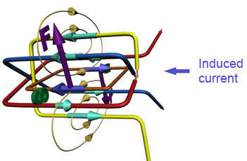 The influence of a rotating magnetic field on a closed conductor with current
Squirrel cage rotor of the induction motor
An induction electric motor works according to this principle also. Instead of a frame with a current inside an asynchronous motor is used a short-circuited rotor resembling a squirrel-cage in construction. A squirrel-cage rotor consists of rods shorted by the end rings.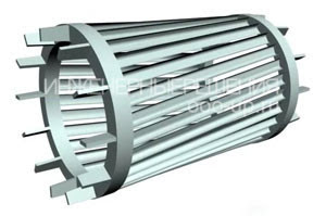 Short-circuited “squirrel-cage” rotor most widely used in asynchronous electric motors (shown without shaft and core)
Three-phase alternating current, passing through the stator windings, creates a rotating magnetic field. Thus, just as described earlier, a current will be induced in the rotor bars, causing the rotor start to rotate. In the figure below you can notice the difference between the induced currents in the rods. This is due to the fact that the magnitude of the change in the magnetic field differs in different pairs of rods, due to their different location relative to the field. The change in current in the rods will change with time.

Rotating magnetic field penetrating squirrel-cage rotor
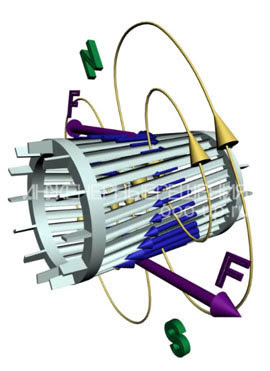 Magnetic torque acting on the rotor
You may also notice that the rotor rods are inclined relative to the axis of rotation. This is done in order to reduce the higher harmonics of the EMF and prevent torque fluctuation. If the rods were directed along the axis of rotation, then a pulsating magnetic field would arise in them due to the fact that the magnetic resistance of the winding is much higher than the magnetic resistance of the stator teeth.
Induction motor slip. Rotor speed
A distinctive feature of an induction motor is that the rotor speed n2 is less than the synchronous speed of rotation of the stator magnetic field n1.
This is explained by the fact that the EMF in the rotor winding rods is induced only when the rotation speed is unequal n2

- where s is the slip of an induction motor,
- n1 – speed of the stator magnetic field, rpm,
- n2 – rotor speed, rpm,
Consider the case where the rotor speed will coincide with the frequency of rotation of the stator magnetic field. In this case, the relative magnetic field of the rotor will be constant, so EMF will not be generated in the rotor bars, and hence the current will not be generated. This means that the force acting on the rotor will be zero. Thus the rotor will slow down. After that, an alternating magnetic field will again act on the rotor bars, thus the induced current and force will increase. In reality, the rotor of an asynchronous electric motor will never reach the speed of rotation of the stator magnetic field. The rotor will rotate at a certain speed which is slightly less than the synchronous speed.
Slip induction motor can vary in the range from 0 to 1, ie, 0-100%. If s ~ 0, then this corresponds to idling mode, when the rotor of the motor practically does not experience the load torque; if s = 1 – short circuit mode in which the motor rotor is stationary (n2 = 0). Slip depends on the mechanical load on the motor shaft and increases with its growth.
The slip corresponding to the rated load of the motor is called the rated (nominal) slip. For low and medium power asynchronous motors, the rated slip varies from 8% to 2%.
Energy conversion
An induction motor converts the electrical energy supplied to the stator windings into mechanical energy (rotation of the rotor shaft). But the input and output power are not equal to each other as during the conversion energy loss occurs: friction, heating, eddy currents and hysteresis losses. This energy is dissipated as heat. Therefore, the asynchronous motor has a fan for cooling.
Induction motor connection
Three phase alternating current
The three-phase alternating current (AC) power grid is the most widely distributed among electrical power transmission systems. The main advantage of a three-phase system compared to single-phase and two-phase systems is its efficiency. In a three-phase circuit, the energy is transmitted through three wires, and the currents flowing in different wires are shifted relative to each other in phase by 120°, while the sinusoidal EMF at different phases have the same frequency and amplitude. Three-phase current (phase difference 120°)
Star and delta
The three-phase winding of the electric motor stator is connected according to the “star” or “delta” wiring diagram, depending on the supply voltage of the grid. The leads of the three-phase winding can be: connected inside the electric motor (three wires go out of the motor), brought out (six wires go out), brought into the junction box (six wires go out to the box, three out of the box).
Phase voltage – the potential difference between the beginning and end of one phase. Another definition for star connection: phase voltage is the potential difference between a line wire and a neutral (note that neutral not available in delta connection).
Line voltage (line-to-line voltage) – in a polyphase system is the potential difference between two linear wires (between phases).
Attention: Although the power for the star and delta connections is calculated using the same formula, connecting the same motor with different connection scheme to the same electrical grid will result in different power consumption. If this is not the correct connection of the electric motor, it can lead to the melting of the stator windings.
Example: Suppose an electric motor was connected according to the “star” diagram to a three-phase AC grid Ul=380 V (respectively Up=220 V) and consumed a current Il=1 A. Total power consumption:
S = 1,73∙380∙1 = 658 W.
Now we change the wiring diagram to “delta”, the line voltage will remain the same Ul=380 V, and the phase voltage will increase by the square root of 3 times Up=Ul= 380 V. An increase in the phase voltage will increase the phase current by the square root of 3. Thus, the line current of the delta connection will be three times the linear current of the star circuit. Consequently, the power consumption will be 3 times more:
S = 1,73∙380∙3 = 1975 W.
Thus, if the motor is designed to be connected to a three-phase AC grid using a star diagram, connecting this motor using a delta diagram can break it.
If in normal mode the electric motor is connected according to the “delta” scheme, then in order to reduce the starting currents during the start-up period, it can be connected according to the “star” scheme. In this case, together with the starting current, the starting torque will also decrease.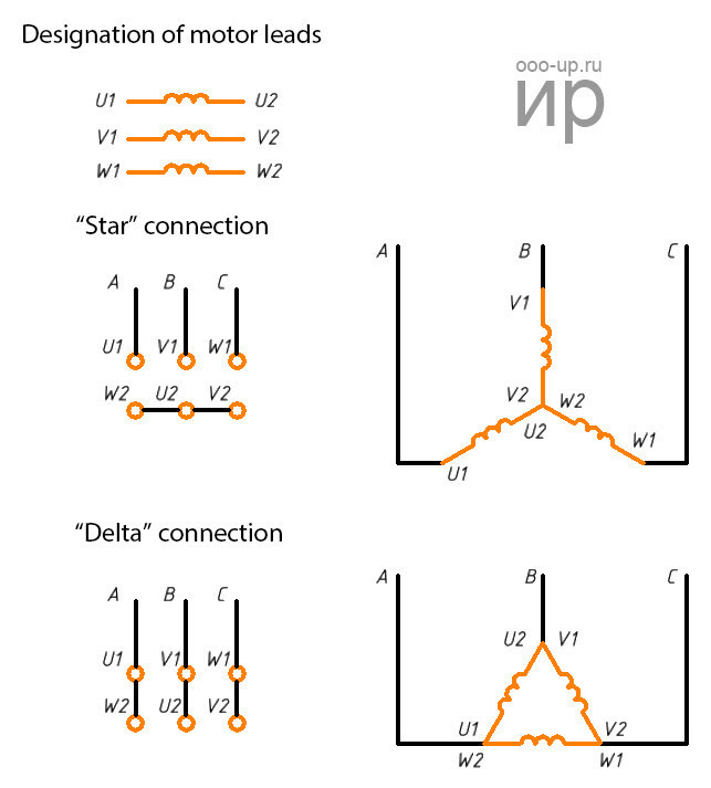
Connection of the electric motor according to the star and delta diagram
Marking of three-phase motor stator terminals
Terminal markings of the stator windings of the three-phase machines according to GOST 26772-85 [2] and IEC 60034-8-2014 [4]
![Marking of three-phase motor stator terminals Terminal markings of the stator windings of the three-phase machines according to GOST 26772-85 [2] and IEC 60034-8-2014 [4] Marking of three-phase motor stator terminals Terminal markings of the stator windings of the three-phase machines according to GOST 26772-85 [2] and IEC 60034-8-2014 [4]](https://ci5.googleusercontent.com/proxy/BijSmWZXptcbZ0N62ay9JdeNZz7IXf15nmVk6iQzEcR12QBjr3Y4DRU2yBKIa8sa03pqfilZJVHzIF2aBVMzw_Sw0Jngi5KSgjxP-wICUVeUNLQRPTRsKTVrKK0_oeSRVAaj88re0mKVszpUxW88B7jtu_e2NeKkopX9Dcc49TqWCU_zk4LsZ8MKFHQy7ItweyK0cqHi6OD8e8zxRNauIUK0ohWXnGo=s0-d-e1-ft#https://i0.wp.com/s3.amazonaws.com/images.wealthyaffiliate.com/uploads/2588097/sitecontent/1515a0aefe7f11906302739a68b64050_cropped.jpg?w=750&ssl=1)
Connection of a three-phase induction motor to a single-phase power using a phase-shifting passive element
Three-phase asynchronous motors can be connected to a single-phase network using phase-shifting elements. In this case, the electric motor will operate either in mode of the single-phase motor with auxiliary winding (fig. a, b, d) or in mode of the two-phase motor with a permanently working running capacitor (fig. c, e, f).
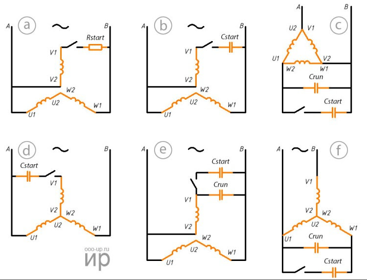
Wiring diagrams of a three-phase induction motor to a single-phase power
The diagrams, shown in figure “a”, “b”, “e”, are applied when all six ends of the winding are brought out. Electric motors with a winding connection according to the schemes “a”, “b”, “d” are almost equivalent to motors that are designed as single-phase induction electric motors with starting winding. With such wiring diagram the rated power is 40-50% of the power in three-phase mode, and when working with a running capacitor 75-80%.
The capacity of the running capacitor at a frequency of 50 Hz for the wiring diagrams “c”, “e”, “f” is approximately calculated, respectively, by the formulas:

- ,where Crun – is the capacity of the running capacitor, uF,
- Irated – rated (phase) stator current of a three-phase motor, A
- U1 – voltage of the single-phase power grid, V.
Induction motor control
Techniques for connecting an AC induction motor to the mains:
- direct power connection
- connection from the soft starter
- connection from the variable frequency drive (vfd)
- Techniques for connecting an AC induction motor to the mains:
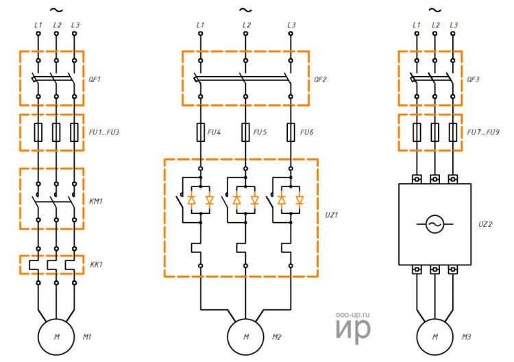
Variants for connecting an AC induction motor using a magnetic starter (left), soft starter (center) and variable frequency drive (right). Wiring diagrams are presented in a simplified form.
FU1-FU9 – fuses, KK1 – thermal relay, KM1 – magnetic starter, L1-L3 – terminals for connection to three-phase AC power, M1-M3 – AC induction electric motors, QF1-QF3 – circuit breakers, UZ1 – soft starter, UZ2 – frequency converter (vfd)
Direct-on-line starting
The use of magnetic starters allows you to control asynchronous motors by directly connecting the motor to the AC power grid.
With the help of magnetic starters, you can implement the scheme:
- non-reversing start: start and stop;
- reversing start: start, stop and reverse.
The use of a thermal relay allows protect of the motor against current values much higher than the nominal value.
Non-reversing starter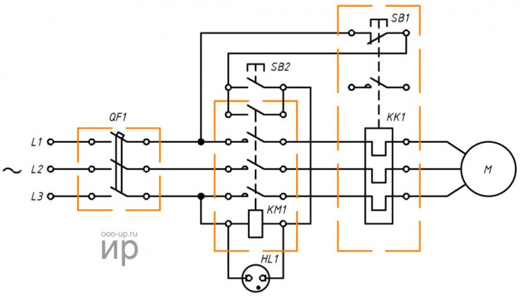
Wiring diagram of the non-reversing starter. Non-reversing connection a three-phase induction motor to a three-phase power grid of alternating electric current through a magnetic contactor
L1, L2, L3 – terminals for connection to three-phase AC power, QF1 – circuit breaker, SB1 – stop button, SB2 – start button, KM1 – magnetic contactor, KK1 – thermal relay, HL1 – warning lamp, M – three-phase AC induction motor
Reversing starter
Wiring diagram of the reversing starter. Reversing connection a three-phase induction motor to a three-phase AC power grid through a magnetic contactor
L1, L2, L3 – terminals for connection to three-phase AC power, QF1 – circuit breaker, KM1, KM2 – magnetic contactors, KK1 – thermal relay, M – three-phase AC induction motor, SB1 – stop button, SB2 – “forward” start button, SB3 – “back” (reverse) start button, HL1, HL2 – warning lamps
The disadvantage of direct commutation of the windings of the asynchronous electric motor with the power grid is the presence of large starting currents during start electric motor.
Soft start of an induction motor
In tasks where adjustment of the motor speed is not required during operation, a soft starter is used to reduce the starting currents at start.
The soft starter protects the induction motor from damage caused by a huge increase in energy consumption during start-up by limiting inrush currents. The soft starter device allows for smooth acceleration and deceleration of the induction motor.
A soft starter is cheaper and more compact than a variable frequency drive. It is used where the adjustment of the motor speed and torque is required only at start-up.
Speed and torque control of an induction motor
Variable frequency drive is using to control the rotational speed and torque of an induction motor. The principle of operation of the variable frequency drive is based on the change of frequency and voltage of alternating current.
- Using a variable frequency drive allows you to:
- reduce power consumption of the electric motor;
- control the electric motor speed (soft start and stop, speed adjustment during operation);
- avoid overloading the motor and thereby increase its service life.

Functional diagram of the variable frequency drive
- Depending on the functional the variable frequency drives implement the following techniques of control an asynchronous motor:
- scalar control;
- vector control.
Scalar control is simple and cheap to implement, but has the following disadvantages — a slow response to load changes and a small control range. Therefore, scalar control is usually used in tasks where the load is either constant or varies according to a known law (for example, fan control).
Scalar control of an induction motor with speed sensor
Vector control is used in tasks where it is required to independently control the speed and torque of an electric motor (for example, an elevator), which, in particular, makes it possible to maintain a constant rotation speed with varying load torque. At the same time, vector control is the most efficient control from the point of view of energy conversion efficiency and increasing the operating time of the electric motor.
Among the vector control techniques of an induction electric motors, the most widely used are: field oriented control and direct torque control.

Induction motor field oriented control with rotor position sensor
Field-oriented control allows you to smoothly and accurately control the motion parameters (speed and torque), but its implementation requires information about the direction of the motor’s rotor flux vector.
- According to the method of obtaining information about the position of the rotor flux linkage of the electric motor, there are:
- sensored field oriented control;
- sensorless field oriented control: the rotor flux linkage position is calculated mathematically based on the information available in the variable frequency drive (supply voltage, stator voltages and currents, resistance and inductance of the stator and rotor windings, number of pole pairs in motor).

Sensorless field oriented control of induction motor
Direct torque control has a simple scheme and high dynamics of work, but at the same time high ripple of torque and current.
Three phase wound rotor motor
Wound rotor induction motor (WRIM) – an induction motor, in which the rotor winding is attached to slip rings [1].
Prior to widespread variable frequency drives, induction motors of medium and high power were made with a wound rotor. Three-phase induction motors with a wound rotor were usually used in devices with severe starting conditions, for example, as crane AC motors, or to drive devices that require smooth control of the rotational speed.
WRIM construction
Wound rotor
Structurally, the wound rotor is a three-phase winding (similar to the stator winding) laid in the slots of the rotor core. The ends of the phases of such a rotor winding are usually connected in a “star”, and the beginning is connected to slip rings, isolated from each other and from the shaft. A three-phase starting or adjusting rheostat is usually connected to the slip rings via brushes. Wound rotor induction motors have a more complex structure than squirrel-cage motors, however, they have better starting and adjusting properties.
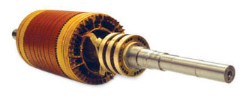
Wound rotor
WRIM stator
The stator of induction motor with a wound rotor (WRIM) does not differ in design from the stator of an induction motor with a squirrel-cage rotor (SCIM).
Terminal markings of the secondary windings of the three-phase WRIM
Terminal markings of the rotor windings of the three-phase machines according to GOST 26772-85 [2] and IEC 60034-8-2014 [4]

WRIM start-up
Wound rotor motors are started using a starting resistor in the rotor circuit.
Wirewound and liquid rheostats are used.
 Wirewound rheostats are stepped, and switching from one stage to another is carried out either manually using the controller’s handle, an essential element of which is a shaft with contacts fixed on it, or automatically using contactors or controller with electric drive.
Liquid rheostat is a vessel with electrolyte, in which the electrodes are lowered. The resistance of the rheostat is regulated by changing the immersion depth of the electrodes [3].
To increase efficiency and reduce brush wear, some WRIM contain a special device (short-circuited mechanism), which, after starting, raises the brushes and closes the rings.
With a resistive start, favorable starting characteristics are achieved, since high values of the torques are achieved at low values of starting currents. Currently, WRIM are replaced by a combination of an squirrel-cage induction motor and a variable frequency drive.
References
- GOST 27471-87 Rotating electrical machines. Terms and definitions.
- GOST 26772-85 Rotating electrical machines. Terminal markings and direction of rotation.
- A.I.Voldek. Electrical machines. Textbook for students of higher tech. institutions. Second edition-Leningrad: 1974.
- IEC 60034-8-2014 Rotating electrical machines – Part 8: Terminal markings and direction of rotation
Want to share this great info with others?
Address: No. 10, Qianjia Industrial Zone, Yaoguan Town, Wujin District, Changzhou City, Jiangsu Province, China.
TEL: +86-519-88387662 +86-13337883086 FAX: +86-519-85121683 Connect to social media: |
