Abaqus Hexahedron Writer
739 views
Skip to first unread message

Sihwa Sung
Sep 21, 2015, 7:43:06 AM9/21/15
to dream3d-users
Hello,
I have a question that can I get the orientation information for each grains using the pipe line 'Abaqus Hexahedron Writer'?
I know that I could get the orientation infomation in '.csv' file with the pipe line 'Pack Primary Phase'.
But this pipe line places before the pipe line 'Match Crystallograpy',so I couldn't get the pole figure what I expected as I drew pole figures with Euler Angles in csv file .
After using the 'Abaqus Hexahedron Writer', I could get the five input files for the Abaqus, but there was no information of orientation for each grain. (=Euler angle sets).
I want to make sure weather I can get the expecting pole figure after finishing all processes.
So, is there a manner to check the final pole figures? For example, creating one more .input file which has orientation information and crystallographic information for grians during the .input files for the Abaqus are made.
I'll wait for your answer.
Thank you and have a nice day.
Friendly
Sihwa Sung

Sean Donegan
Oct 7, 2015, 2:33:37 PM10/7/15
to dream3d-users
Hi Sihwa,
If you are interested in seeing a pole figure for your Euler angles, the easiest way is to run the "Write Pole Figure Images" filter. Simply place this filter after your "Match Crystallography" filter and supply it with your Euler angles. You will also have the provide the crystal structures and phases, which should be present in your pipeline since you are creating a synthetic structure. The pole figure filter also requires a mask array, which you may not have in your pipeline. You can create a mask array by using the "Create Data Array" filter. You will want to set the scalar type to "bool", the number if components to 1, and the initialization value to 1. You will also want to put the created array in the same attribute matrix as your Euler angles (probably named CellData).
hope that helps,
-Sean

Vicky Liu
Jan 12, 2016, 7:22:58 AM1/12/16
to dream3d-users
Hi Sean,
I'm a colleague of Sihwa, and now I'm going on with this topic. I still have the same problem with Sihwa.
I tried your suggestion, added "Create Data Array" filter and "Write Pole Figure Images" filter after "Match Crystallography" filter, as shown here:
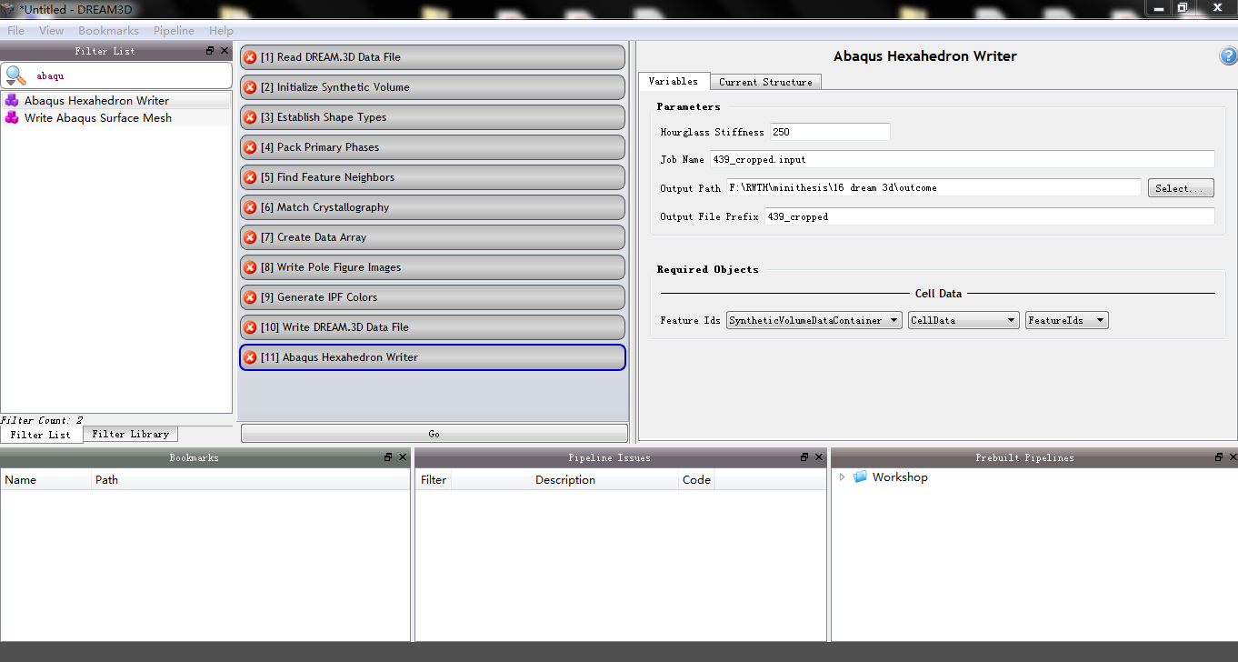
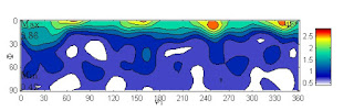
However, after 'Abaqus Hexahedron Writer', I could still get only five input files as well as one csv file, as attached. There was no orientation information in the input files and the orientations from csv file were totally wrong for my material, it's pole figures (this is I plotted the orientations from csv using MTEX):

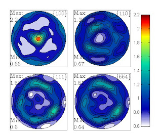
but it should be (this is pole figures in StatsGenerator):

Could you help me check this question? if necessary, I can send you my used experimental data from ebsd.ang file and the used input dream3d file for 'Abaqus Hexahedron Writer', which couldn't be attached here due to the browser problem.
Thanks in advance!
Best regards,
Vicky
Sean Donegan
Jan 14, 2016, 8:26:15 AM1/14/16
to dream3d-users
Hi Vicky,
Just to make sure I understand, you want to be able to export the orientation information so that it can be imported into Abaqus, correct? Currently, the "Abaqus Hexahedron Writer" filter only exports the grain Ids onto the elements; this limitation is mostly because we don't have a license of Abaqus on which to test what the correct file formats are for adding other information, such as Euler angles. If you are able to provide an example Abaqus input file that shows what the format should be for storing such information, I would be happy to update the filter so that it can export the orientation information as well.
-Sean
On Monday, September 21, 2015 at 7:43:06 AM UTC-4, Sihwa Sung wrote:
On Monday, September 21, 2015 at 7:43:06 AM UTC-4, Sihwa Sung wrote:
Vicky Liu
Jan 14, 2016, 6:23:42 PM1/14/16
to dream3d-users
Hi Sean,
Yes, I need the orientation information for Abaqus input.
For my calculation, the crystal plasticity is accomplished by DAMASK,(the Düsseldorf Advanced Material Simulation Kit, MPIE.) and Abaqus is used as the boundary value problem solver. Therefore, there are two kinds of input files: 'material.config' file for the orientation\texture information and material parameters setting of materials, 'REV.inp' file for the nodes setting, elements setting, section setting, boundary conditions setting, process setting, etc.
I attached an example for my simulation, this is a RVE for 0.5*0.5*0.5 with mesh 10*10*10, i.e. 1000 elements, and one element is one grain, so, there is 1000 materials, i.e. 1000 orientations/textures. Hope these will be helpful.
Thanks in advance!
Vicky

latm...@gmail.com
Jan 15, 2016, 7:22:31 AM1/15/16
to dream3d-users
Hi Vicky:
To get orientations, you can use Write Los Alamos FFT filter. This filter writes an ASCII file that contains Euler angles for each voxel.
Then you can write your own MATLAB or Python script to read the data and export it in a format that suits you. See this post for example.
If you use DAMASK, it already has a script (GeomFromVPSC) that should convert Los Alamos FFT files into material.config files (I have not used it myself though).
So you should be able to export ABAQUS mesh using Abaqus Hexagon Writer in Dream.3D, export orientations using Write Los Alamos FFT in Dream.3D, and convert Los Alamos FFT file into material.config file using GeomFromVPSC script in DAMASK.
Marat
Vicky Liu
Jan 15, 2016, 7:18:16 PM1/15/16
to dream3d-users
Hi Marat,
Thank you for your suggestion.
I tried 'Write Los Alamos FFT' filter, It worked and gave a txt file ('AnglesOutput_Step3.txt') with orientation information of every element. As I set the 'Initialize Synthetic Volume' filter with dimensions 15*15*15, it gave 3375 elements with their orientations. But I'm not sure about the meaning of all 8 columns in this txt file. First three should be Euler angles, what are the followed five columns?
Besides, the output orientations were still not so good for my material, I plotted their odf and pole figures (with Euler angles from AnglesOutput_Step3.txt file):
This was still far away from what it should be... Here is the correct odf and pole figures of 3375 discrete orientations from my material as comparison.


Do your have any idea for improving the output orientations from Dream3D?
Thank you again in advance!
Vicky
Sean Donegan
Jan 18, 2016, 8:13:54 AM1/18/16
to dream3d-users
Hi Vicky,
The column data in the Los Alamos FFT file is the following:
[Phi1] [PHI] [Phi2] [X] [Y] [Z] [Grain Id] [Phase Id]
where the Euler angles are in degrees in the Bunge convention, (x,y,z) are the voxel coordinates, and the grain and phase Ids are integer Ids for which grain and phase each voxel belongs to.
You seem to want to match an ODF to one you already have; currently, how are you generating your statistics file that you use to construct your synthetic microstructure? If you already have an ODF as discrete values, then you should read them directly into StatsGenerator when constructing your statistics file. This can be done in the ODF tab in StatsGenerator by selecting the "Bulk Load Weights and Spreads" option. The necessary file format can be found in the "Write StatsGenerator ODF Angle File" filter documentation (in DREAM.3D itself). By creating the ODF in your statistics file this way, DREAM.3D will try and match to that exact ODF.
hope that helps,
-Sean
On Monday, September 21, 2015 at 7:43:06 AM UTC-4, Sihwa Sung wrote:
On Monday, September 21, 2015 at 7:43:06 AM UTC-4, Sihwa Sung wrote:
Vicky Liu
Jan 19, 2016, 5:32:30 AM1/19/16
to dream3d-users
Hi Sean,
Thanks you for your information firstly, I think I need to explain my processes now.
Thanks you for your information firstly, I think I need to explain my processes now.
Step 1, using "Write StatsGenerator ODF Angle files" pipeline to creat a input file(.txt) for StatsGenerator ODF distributions, this input data file was directly from my EBSD measurment results(.ang).
I.e. for this step, input: 439_cropped_EBSD.ang file, output: AnglesOutput_step1.txt file.
Step2, using "StatsGenerator " to creat a Dream3D file with correct grain size, orientation and misorientation distributions.
After this step, I could get the same pole figures with my EBSD measurement, (as I showed in my first message under this topic), so, until this step, everything seems ok and correct.
I.e. for this step, input: AnglesOutput_step1.txt file, output:439_cropped_step2.dream3d file.
Step3, using "Abaqus Hexahedron Writer" pipeline to generate synthetic micro structures with correct grain size and orientation information.
I.e. for this step, input: 439_cropped_step2.dream3d file, output: five 439_cropped.inp files, a 439_cropped_primary.csv file and a AnglesOutput_step3.txt file.
Now, we can see that the orientation distributions from the 439_cropped_primary.csv file or the AnglesOutput_step3.txt file are totally different with my EBSD measurement and step2 StatsGenerator results, as I've already shown before.
That means, I've already given Dream3d all me materials microstructures information using StatsGenerator, unfortunately, Dream3d didnot give the matched microstructure information in the end.
Could you help me to check where the problem is? Is it from step 2 439_cropped_step2.dream3d file or because of the processes in step3?
Thanks again in advance!
Vicky
Sean Donegan
Jan 21, 2016, 9:00:49 AM1/21/16
to dream3d-users
Hi Vicky,
Thank you for explaining your workflow; could you post your angles file that you generate from step 1? This will allow me to work through your process on my end and debug the issue. Also, if it is not too large to post here and you are allowed to, can you post your original .ang file?
thanks,
-Sean
On Monday, September 21, 2015 at 7:43:06 AM UTC-4, Sihwa Sung wrote:
On Monday, September 21, 2015 at 7:43:06 AM UTC-4, Sihwa Sung wrote:
Reply all
Reply to author
Forward
0 new messages