APM 2.6 and 3DR LEA-6H Compass (HMC5883L) - example test sketch, grateful for help
752 views
Skip to first unread message

JP B
Nov 5, 2013, 12:09:53 PM11/5/13
to diyr...@googlegroups.com
Hi,
Have an APM2.6 with external 3DR LEA-6H GPS and Compass. Compass is HMC5883L. I am writing my own firmware to control the rover and get sensor feedback to a UI, and am currently looking at obtaining the compass values.
Upon advice I have calibrated the compass within the APM mission planner> I have then uploaded the example sketch below to the APM to test the compass. I cannot for the life of me get a correct heading calculation (raw x/y/z values seem to be consistent across the several test sketches I have found on the net).
With regard to orientation my compass is laid flat and arrow pointing in "forward" direction of travel for the rover. I wonder whether it is a yaw rotation issue (change calculation to emulate roll of compass on axis), or whether wrong axis used in calculation of heading. Must admit this is driving me a little crazy, so I would appreciate some help in order to retain my hair!
Sample test sketch below:
#include <Wire.h> //I2C Arduino Library
#define address 0x1E //0011110b, I2C 7bit address of HMC5883
void setup(){
//Initialize Serial and I2C communications
Serial.begin(9600);
Wire.begin();
//Put the HMC5883 IC into the correct operating mode
Wire.beginTransmission(address); //open communication with HMC5883
Wire.write(0x02); //select mode register
Wire.write(0x00); //continuous measurement mode
Wire.endTransmission();
}
void loop(){
int x,y,z; //triple axis data
//Tell the HMC5883 where to begin reading data
Wire.beginTransmission(address);
Wire.write(0x03); //select register 3, X MSB register
Wire.endTransmission();
//Read data from each axis, 2 registers per axis
Wire.requestFrom(address, 6);
if(6<=Wire.available()){
x = Wire.read()<<8; //X msb
x |= Wire.read(); //X lsb
z = Wire.read()<<8; //Z msb
z |= Wire.read(); //Z lsb
y = Wire.read()<<8; //Y msb
y |= Wire.read(); //Y lsb
}
//Print out values of each axis
Serial.print("x: ");
Serial.print(x);
Serial.print(" y: ");
Serial.print(y);
Serial.print(" z: ");
Serial.print(z);
float heading = atan2(y, x);
if(heading < 0)
heading += 2*PI;
float headingDegrees = heading * 180/M_PI;
Serial.print(" Heading: ");
Serial.println(headingDegrees);
delay(100);
}
Example output when Rover is pointing due south, as checked with my reliable Suunto Ambit watch compass. If I manually rotate the rover to point due North, the Heading only changes to approx 270.
x: 288 y: -229 z: 575 Heading: 321.51
x: 288 y: -229 z: 574 Heading: 321.51
x: 287 y: -227 z: 574 Heading: 321.66
x: 286 y: -230 z: 573 Heading: 321.19
x: 288 y: -230 z: 574 Heading: 321.39
x: 287 y: -232 z: 573 Heading: 321.05
x: 287 y: -233 z: 573 Heading: 320.93
x: 287 y: -230 z: 573 Heading: 321.29
x: 288 y: -232 z: 573 Heading: 321.15
x: 287 y: -233 z: 572 Heading: 320.93
x: 286 y: -232 z: 573 Heading: 320.95
x: 287 y: -230 z: 573 Heading: 321.29
x: 287 y: -233 z: 573 Heading: 320.93
x: 287 y: -234 z: 573 Heading: 320.81
x: 287 y: -233 z: 573 Heading: 320.93
x: 288 y: -231 z: 573 Heading: 321.27
x: 287 y: -233 z: 573 Heading: 320.93
x: 287 y: -228 z: 574 Heading: 321.54
x: 288 y: -229 z: 574 Heading: 321.51
x: 286 y: -229 z: 574 Heading: 321.32
x: 287 y: -230 z: 574 Heading: 321.29
x: 287 y: -229 z: 574 Heading: 321.41
x: 287 y: -229 z: 574 Heading: 321.41
x: 287 y: -230 z: 574 Heading: 321.29
x: 287 y: -233 z: 572 Heading: 320.93
Thanks for any help.

Wayne Holder
Nov 5, 2013, 12:45:31 PM11/5/13
to diyr...@googlegroups.com
I think you may misunderstand how calibration works. The HMC5883 does not have an internal calibration mechanism that remembes calibration data. Instead, the idea is that you need to adjust the x/y/z values to compensate for offsets before trying to use them to compute a heading angle. I recommend that you capture a set of x/y data as you slowly rotate the compass module around the Z axis, then plot the X/Y data using a tool like Excel. In an ideal world, this data would plot a perfect circle around the origin. But, I think you'll find that it does not. For more on this, see my short article on my own adventures with compass calibration at:
https://sites.google.com/site/wayneholder/self-driving-rc-car/calibrating-the-compass
Waynehttps://sites.google.com/site/wayneholder/self-driving-rc-car/calibrating-the-compass
--
You received this message because you are subscribed to the Google Groups "diyrovers" group.
To unsubscribe from this group and stop receiving emails from it, send an email to diyrovers+...@googlegroups.com.
To post to this group, send email to diyr...@googlegroups.com.
To view this discussion on the web visit https://groups.google.com/d/msgid/diyrovers/36e512d9-cb50-4931-b5a5-10d266f8d829%40googlegroups.com.
For more options, visit https://groups.google.com/groups/opt_out.
JP B
Nov 5, 2013, 1:05:30 PM11/5/13
to diyr...@googlegroups.com
Hi Wayne,
Thank-you for your very helpful and informative reply. I read your article and that does help to explain, and also helps define the purpose of the derived offset shown when using the standard APM mission planner compass calibration.
Curiously though when uploading and executing the example compass sketch from the AP_Compass library I get weird heading results, even though from reviewing the code it performs a calibration.
I will continue my investigation , of course if you have any example sketches or excel sheets to assist that would be most welcome to save some time, however I will persevere! Thanks again.

jesse brockmann
Nov 5, 2013, 1:06:07 PM11/5/13
to diyr...@googlegroups.com
When you do the calibration via the Mission Planner, it will calculate the values for calibration, and normally those are written to the EEPROM on the controller. The controller software will then read in the values, and those values are used during the calculation of heading. What I've heard of is using a calibration that is done with each startup. This is done by doing a couple circles, then using the min/max values for the evaluation.
I wish someone would come out with a true compass module that just works and has like 0.1 degrees accuracy. The modules being used now are just magnetometers, that is they measure magnetic fields, but they do not say you are at a heading of 80 degrees, etc. That requires a bunch of math, certain data about the module being used, even data about the location where the module is being used. Pipes, wires, buildings can all change the magnetic fields. But it seems right now that is just a dream. The calibration of those modules is tricky, and best case seems to be 1 degree of accuracy.
To view this discussion on the web visit https://groups.google.com/d/msgid/diyrovers/CAB%2BjonBa98kOA3s5pyt8owsr4%3D1vVOKsF_U0%3DovBPxGrdq0dhw%40mail.gmail.com.
JP B
Nov 5, 2013, 1:15:53 PM11/5/13
to diyr...@googlegroups.com
I have just performed the compass calibration again in MP, here are the calculated offsets:


Jon Watte
Nov 5, 2013, 1:20:46 PM11/5/13
to diyrovers
from reviewing the code it performs a calibration
Does it actually drive the rover in a circle while doing that?
A suitable calibration needs to exercise the entire 360 degrees of orientation.
Sincerely,
jw
Sincerely,
Jon Watte
--
"I pledge allegiance to the flag of the United States of America, and to the republic for which it stands, one nation indivisible, with liberty and justice for all."
~ Adopted by U.S. Congress, June 22, 1942
To view this discussion on the web visit https://groups.google.com/d/msgid/diyrovers/3d548c60-9b71-4bfd-a8fe-b339bac2e7d0%40googlegroups.com.
JP B
Nov 5, 2013, 1:24:37 PM11/5/13
to diyr...@googlegroups.com
The calibration just asked to move the compass through all 6 axis - simply hand-held rover and rotated.
Wayne Holder
Nov 5, 2013, 1:46:15 PM11/5/13
to diyr...@googlegroups.com
I wish I could say that magnetometers were easy beasts to work with but, in my experience, they're rather finicky, Here are a few things I've learned:
1. Magnetometers are easily influenced by their placement relative to other ferrous objects, motors, magnets, etc. So, calibration must be done after the magnetometer is installed where it's going to be used in the vehicle. In fact, if anything changes in the vehicle, such as adding, or removing any component (including things like battery packs), you should recalibrate.4. Remember that you need to adjust for magnetic declination to get a reading relative to true north. If this is new to you, see this Wikipedia article: http://en.wikipedia.org/wiki/Magnetic_declination for details.
5. Don't forget about the Z axis. You may need to use some kind of tilt compensation code if your vehicle can pitch or roll a lot. I find this can sometimes be ignored for ground vehicles that have a stable suspension, but it can still cause problems when turning at high speeds.
To view this discussion on the web visit https://groups.google.com/d/msgid/diyrovers/3d548c60-9b71-4bfd-a8fe-b339bac2e7d0%40googlegroups.com.
JP B
Nov 5, 2013, 3:02:33 PM11/5/13
to diyr...@googlegroups.com
Well Wayne, tonight has been an education, first ever time creating scatter graphs in Excel!
From my understanding the aim is to use offsets to centre around 0? In this case (approximate) offsets are -160 for X and -400 for Y, which plots as:
After taking 63 readings during the rotation of rover (with compass mounted/installed) here is the X/Y scatter graph before any offsets applied (looking very much like your second motor graph in your article):
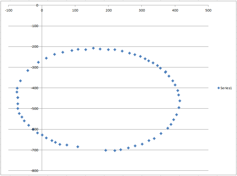
From my understanding the aim is to use offsets to centre around 0? In this case (approximate) offsets are -160 for X and -400 for Y, which plots as:

The plots are looking more oval than circular. I would appreciate your insights.
I assume these X/Y offsets are applied to the calculated magnetic X/Y from the compass before a heading is calculated? I took the opportunity to try this however I still get unexpected heading values - I suspect I perhaps need to adjust the Y for the compass is mounted in the 3DR LEA-6H GPS housing (180 degree roll perhaps)?
Thanks for the education thus far!
Wayne Holder
Nov 5, 2013, 3:26:42 PM11/5/13
to diyr...@googlegroups.com
It looks like you're on the right track. I think all you need to do now is scale the X axis to match the scale of the Y axis so you can get a circle rather than an oval. Something along the lines of multiplying the x values by (maxX - minX) / (maxY - minY). However, graph again to see if you got it right. Then, I simply use atan2() to calculate the angle.
WayneTo view this discussion on the web visit https://groups.google.com/d/msgid/diyrovers/46b3d1ed-b82d-4b97-ab93-3d217483e3ec%40googlegroups.com.
JP B
Nov 5, 2013, 3:29:09 PM11/5/13
to diyr...@googlegroups.com
However, having just thought about this a little more, surely it doesn't matter about the Y axis (for now) - I assume these values from the compass are radians? I have an X radian and Y radian from which I should eb able to calculate a heading. From the resources I have seen on the net the calculation in the posted sketch looks correct, grateful for any comment:
float heading = atan2(y, x);
if(heading < 0)
heading += 2*PI;
float headingDegrees = heading * 180/M_PI;
I put specific X/Y values (adjusted with offset) through the calculation, to get a heading. In brackets is the heading obtained from my Suunto Ambit GPS watch, logged when making the initial X/Y log (with the first two values I almost would have said just a rotation of 90 degrees would have done it, but the last two recordings blow it).
x: 32 y: -302 Heading: 276.05 (watch = 0 deg)
x: -234 y: -1 Heading: 180.24 (watch = 94 deg)
x: 81 y: 178 Heading: 65.53 (watch = 200 deg)
x: 236 y: -154 Heading: 326.87 (watch = 300 deg)
Wayne Holder
Nov 5, 2013, 3:40:06 PM11/5/13
to diyr...@googlegroups.com
Yes. With atan2() you're going to get the angle in radians. I didn't see a sketch posted but, if you're working with excel, you should be able to test all the calculations in there using the sample data you captured. Then, you can graph the output from atan2(), which should produce a sawtooth like graph.
Wayne--
You received this message because you are subscribed to the Google Groups "diyrovers" group.
To unsubscribe from this group and stop receiving emails from it, send an email to diyrovers+...@googlegroups.com.
To post to this group, send email to diyr...@googlegroups.com.
To view this discussion on the web visit https://groups.google.com/d/msgid/diyrovers/d97ba01d-6de0-4ca9-bcbc-4b3c78166cdf%40googlegroups.com.

Michael Shimniok
Nov 5, 2013, 4:08:55 PM11/5/13
to diyr...@googlegroups.com
On 11/05/2013 01:02 PM, JP B wrote:
> The plots are looking more oval than circular. I would appreciate
> your insights.
That's just a scaling issue. one axis is more sensitive than the other.
> The plots are looking more oval than circular. I would appreciate
> your insights.
Here's my write-up if it helps:
http://www.bot-thoughts.com/2011/04/quick-and-dirty-compass-calibration-in.html
Beware outliers in your data points.
> I assume these X/Y offsets are applied to the calculated magnetic X/Y
> from the compass before a heading is calculated?
scale them with a multiplier, like I do in my code here:
void Sensors::Read_Compass()
{
_compass.readMag(m);
for (int i=0; i < 3; i++) {
mag[i] = ((float) m[i] - m_offset[i]) * m_scale[i] * m_sign[i];
}
return;
}
> I took the opportunity to try this however I still get unexpected
> heading values - I suspect I perhaps need to adjust the Y for the
> compass is mounted in the 3DR LEA-6H GPS housing (180 degree roll
> perhaps)?
Yup. There's the orientation (X should be the long axis of the vehicle,
> I took the opportunity to try this however I still get unexpected
> heading values - I suspect I perhaps need to adjust the Y for the
> compass is mounted in the 3DR LEA-6H GPS housing (180 degree roll
> perhaps)?
Y transverse, and Z vertical) then there's sign for each axis, too.
Michael
Jon Watte
Nov 5, 2013, 4:18:58 PM11/5/13
to diyrovers
Also, the magnetic field away from the (magnetic) equator will be aimed diagonally into the Earth. Thus, even with perfectly equal sensitivity, you will see an oval cross section, because the "circle" is in the plane of the field, and thus includes a Z component.
Some math that helps in calibrating these things is calculating the covariance matrix. Invert that and you'll get three basis axes as well as an average to subtract from the readings, which will allow you to do the proper 3D transforms to get a "real" circle, and will also by reference let you calculate the orientation of your bot!
Sincerely,
jw
Sincerely,
Jon Watte
--
"I pledge allegiance to the flag of the United States of America, and to the republic for which it stands, one nation indivisible, with liberty and justice for all."
~ Adopted by U.S. Congress, June 22, 1942
--
You received this message because you are subscribed to the Google Groups "diyrovers" group.
To unsubscribe from this group and stop receiving emails from it, send an email to diyrovers+unsubscribe@googlegroups.com.
To view this discussion on the web visit https://groups.google.com/d/msgid/diyrovers/52795E67.8070709%40gmail.com.
JP B
Nov 6, 2013, 5:39:26 AM11/6/13
to diyr...@googlegroups.com
I want to say a big thank-you to all of you have given great contributions in aiding my understand of this topic, helping improve my maths (still fairly sub-standard!!) and thinking of ways to test and calibrate instruments in general.
As you will know yourselves, building a rover is a journey - there is so much to learn, about a multitude of different topics. Sometimes my head aches with all the new knowledge, but it is so satisfying to see something working, to get a physical reaction from a creation you have made.
Now I know a littler more about magnetometers - a bit rough around the edges, but it's up and running, yeah!
After applying the offsets and scaling, I now get this nice circular pattern:

After calculating the radians angle with atan2, I get the following, just as Wayne indicated:

Then again similar after applying calculation for heading in degrees:

And now with a working test sketch to provide heading in degrees. Note I was off by 180 degrees - rover pointing north gave a heading of 180, rover pointing south a heading of 360, so you can see an adjustment in the sketch for this - I welcome any suggestions that are smarter than the "patch" I have applied to correct this.
Thanks again all, now to the gyro!
#include <Wire.h> //I2C Arduino Library
#define address 0x1E //0011110b, I2C 7bit address of HMC5883
void setup(){
//Initialize Serial and I2C communications
Serial.begin(9600);
Wire.begin();
//Put the HMC5883 IC into the correct operating mode
Wire.beginTransmission(address); //open communication with HMC5883
Wire.write(0x02); //select mode register
Wire.write(0x00); //continuous measurement mode
Wire.endTransmission();
}
void loop(){
int xmag,
ymag,
zmag;
int xoffset = -160;
int yoffset = -460;
float xscale = 0.95639;
float xadjusted;
float yadjusted;
//Tell the HMC5883 where to begin reading data
Wire.beginTransmission(address);
Wire.write(0x03); //select register 3, X MSB register
Wire.endTransmission();
//Read data from each axis, 2 registers per axis
Wire.requestFrom(address, 6);
if(6<=Wire.available()){
xmag = Wire.read()<<8; //X msb
xmag |= Wire.read(); //X lsb
zmag = Wire.read()<<8; //Z msb
zmag |= Wire.read(); //Z lsb
ymag = Wire.read()<<8; //Y msb
ymag |= Wire.read(); //Y lsb
}
xadjusted = (xmag + xoffset) * xscale;
yadjusted = (ymag - yoffset);
float heading_radian = atan2(xadjusted, yadjusted);
if (heading_radian < 0) {
heading_radian += 2*PI;
}
float heading_degrees = heading_radian * (180/M_PI);
heading_degrees -= 180;
if (heading_degrees < 0){
heading_degrees += 360;
}
Serial.print(" Heading: ");
Serial.println(heading_degrees);
delay(100);
}
Michael Shimniok
Nov 6, 2013, 11:18:49 AM11/6/13
to diyr...@googlegroups.com
> And now with a working test sketch to provide heading in degrees.
> Note I was off by 180 degrees - rover pointing north gave a heading of
> 180, rover pointing south a heading of 360, so you can see an
> adjustment in the sketch for this - I welcome any suggestions that are
> smarter than the "patch" I have applied to correct this.
Or Y axis, either one? (ie, board mounted upside down or backwards). Or
did my coffee not yet counteract my lack of sleep? :) I am sure I've
seen in ArduPilot and/or ArduIMU code some #defines to set the sign of
each axis of each sensor... ?
JP B
Nov 6, 2013, 11:32:20 AM11/6/13
to diyr...@googlegroups.com
Hi Michael,
Thanks. Yes you are right, there is some work in the standard code to determine if roll of any axis should be done, snippet from AP_Compass_HMC5843.cpp
// rotate to the desired orientation
Vector3f rot_mag = Vector3f(mag_x,mag_y,mag_z);
if (product_id == AP_COMPASS_TYPE_HMC5883L) {
rot_mag.rotate(ROTATION_YAW_90);
}
// apply default board orientation for this compass type. This is
// a noop on most boards
rot_mag.rotate(MAG_BOARD_ORIENTATION);
which executes rotate in vector3.cpp of AP_Math library. The more I look at the standard code the more I marvel (and in fear of) it's complexity. I haven't had enough coffee either, and don't plan to as I need sleep tonight after this compass thing buzzing my head last evening, so what I have will do for now as it works - not elegant, but I'll come back to it later to add declination etc.
void Vector3<T>::rotate(enum Rotation rotation)
{
T tmp;
switch (rotation) {
case ROTATION_NONE:
case ROTATION_MAX:
return;
case ROTATION_YAW_45: {
tmp = HALF_SQRT_2*(x - y);
y = HALF_SQRT_2*(x + y);
x = tmp;
return;
}
case ROTATION_YAW_90: {
tmp = x; x = -y; y = tmp;
return;
}
case ROTATION_YAW_135: {
tmp = -HALF_SQRT_2*(x + y);
y = HALF_SQRT_2*(x - y);
x = tmp;
return;
}
case ROTATION_YAW_180:
x = -x; y = -y;
return;
case ROTATION_YAW_225: {
tmp = HALF_SQRT_2*(y - x);
y = -HALF_SQRT_2*(x + y);
x = tmp;
return;
}
case ROTATION_YAW_270: {
tmp = x; x = y; y = -tmp;
return;
}
case ROTATION_YAW_315: {
tmp = HALF_SQRT_2*(x + y);
y = HALF_SQRT_2*(y - x);
x = tmp;
return;
}
case ROTATION_ROLL_180: {
y = -y; z = -z;
return;
}
case ROTATION_ROLL_180_YAW_45: {
tmp = HALF_SQRT_2*(x + y);
y = HALF_SQRT_2*(x - y);
x = tmp; z = -z;
return;
}
case ROTATION_ROLL_180_YAW_90: {
tmp = x; x = y; y = tmp; z = -z;
return;
}
case ROTATION_ROLL_180_YAW_135: {
tmp = HALF_SQRT_2*(y - x);
y = HALF_SQRT_2*(y + x);
x = tmp; z = -z;
return;
}
case ROTATION_PITCH_180: {
x = -x; z = -z;
return;
}
case ROTATION_ROLL_180_YAW_225: {
tmp = -HALF_SQRT_2*(x + y);
y = HALF_SQRT_2*(y - x);
x = tmp; z = -z;
return;
}
case ROTATION_ROLL_180_YAW_270: {
tmp = x; x = -y; y = -tmp; z = -z;
return;
}
case ROTATION_ROLL_180_YAW_315: {
tmp = HALF_SQRT_2*(x - y);
y = -HALF_SQRT_2*(x + y);
x = tmp; z = -z;
return;
}
case ROTATION_ROLL_90: {
tmp = z; z = y; y = -tmp;
return;
}
case ROTATION_ROLL_90_YAW_45: {
tmp = z; z = y; y = -tmp;
tmp = HALF_SQRT_2*(x - y);
y = HALF_SQRT_2*(x + y);
x = tmp;
return;
}
case ROTATION_ROLL_90_YAW_90: {
tmp = z; z = y; y = -tmp;
tmp = x; x = -y; y = tmp;
return;
}
case ROTATION_ROLL_90_YAW_135: {
tmp = z; z = y; y = -tmp;
tmp = -HALF_SQRT_2*(x + y);
y = HALF_SQRT_2*(x - y);
x = tmp;
return;
}
case ROTATION_ROLL_270: {
tmp = z; z = -y; y = tmp;
return;
}
etc etc
Michael Shimniok
Nov 6, 2013, 11:40:20 AM11/6/13
to diyr...@googlegroups.com
On 11/06/2013 09:32 AM, JP B wrote:
> Thanks. Yes you are right, there is some work in the standard code to
> determine if roll of any axis should be done, snippet from
> AP_Compass_HMC5843.cpp
Hm, that's different than I imagined. Here's what I saw last, which
> Thanks. Yes you are right, there is some work in the standard code to
> determine if roll of any axis should be done, snippet from
> AP_Compass_HMC5843.cpp
comes out of Pololu's MinIMU9AHRS software which was based AFAIK on
ArduIMU. This is in Compass.pde:
// adjust for LSM303 compass axis offsets/sensitivity differences by
scaling to +/-0.5 range
c_magnetom_x = (float)(magnetom_x - SENSOR_SIGN[6]*M_X_MIN) /
(M_X_MAX - M_X_MIN) - SENSOR_SIGN[6]*0.5;
c_magnetom_y = (float)(magnetom_y - SENSOR_SIGN[7]*M_Y_MIN) /
(M_Y_MAX - M_Y_MIN) - SENSOR_SIGN[7]*0.5;
c_magnetom_z = (float)(magnetom_z - SENSOR_SIGN[8]*M_Z_MIN) /
(M_Z_MAX - M_Z_MIN) - SENSOR_SIGN[8]*0.5;
Where
int SENSOR_SIGN[9] = {1,1,1,-1,-1,-1,1,1,1}; //Correct directions x,y,z
- gyro, accelerometer, magnetometer
is declared in MinIMU9AHRS.pde
Michael
Wayne Holder
Nov 6, 2013, 11:40:44 AM11/6/13
to diyr...@googlegroups.com
It sounds like you've made great progress. Congratulations! One way to fix the rotation by 180 issue (if I understand you correctly) is to just flip the sign of that axis value in the input to atan2().
And, you're very right in saying that building a rover is a journey. I probably devote far more time to this hobby than is practical, or reasonable, but it's just such a fascinatingly complex problem that I can't resist trying to build better and better solutions.
--
You received this message because you are subscribed to the Google Groups "diyrovers" group.
To unsubscribe from this group and stop receiving emails from it, send an email to diyrovers+...@googlegroups.com.
To view this discussion on the web visit https://groups.google.com/d/msgid/diyrovers/c29900bd-1029-4979-a84e-b3528f7568e3%40googlegroups.com.
Jon Watte
Nov 6, 2013, 5:06:44 PM11/6/13
to diyrovers
If you flip just one sign in atan2(), you will go from left-handed to right-handed space, so it will increase going counterclockwise. Not what you want.
If you want to rotate by 180 degrees, negate BOTH input values to atan2() (this is a 180 degree rotation.)
Sincerely,
jw
Sincerely,
Jon Watte
--
"I pledge allegiance to the flag of the United States of America, and to the republic for which it stands, one nation indivisible, with liberty and justice for all."
~ Adopted by U.S. Congress, June 22, 1942
To view this discussion on the web visit https://groups.google.com/d/msgid/diyrovers/CAB%2BjonDHUffK3LHiZODctfASjCUdFdfvNE%3DJ7sCxiktAD3%3D3Ag%40mail.gmail.com.
Wayne Holder
Nov 6, 2013, 5:15:13 PM11/6/13
to diyr...@googlegroups.com
Yup. My mistake. Thanks for the correction.
WayneTo view this discussion on the web visit https://groups.google.com/d/msgid/diyrovers/CAJgyHGNw8H2mOqDUHgmsk2X7-BxMnAw8cg5akx-k4ijvkYUJkA%40mail.gmail.com.
Reply all
Reply to author
Forward
0 new messages