Turnigy Accucell 8150 Problem
502 views
Skip to first unread message

surroot
Feb 7, 2015, 6:12:38 AM2/7/15
to cheali-...@googlegroups.com
Hi there!
I have a problem with my Turnigy Accucell 8150 charger.
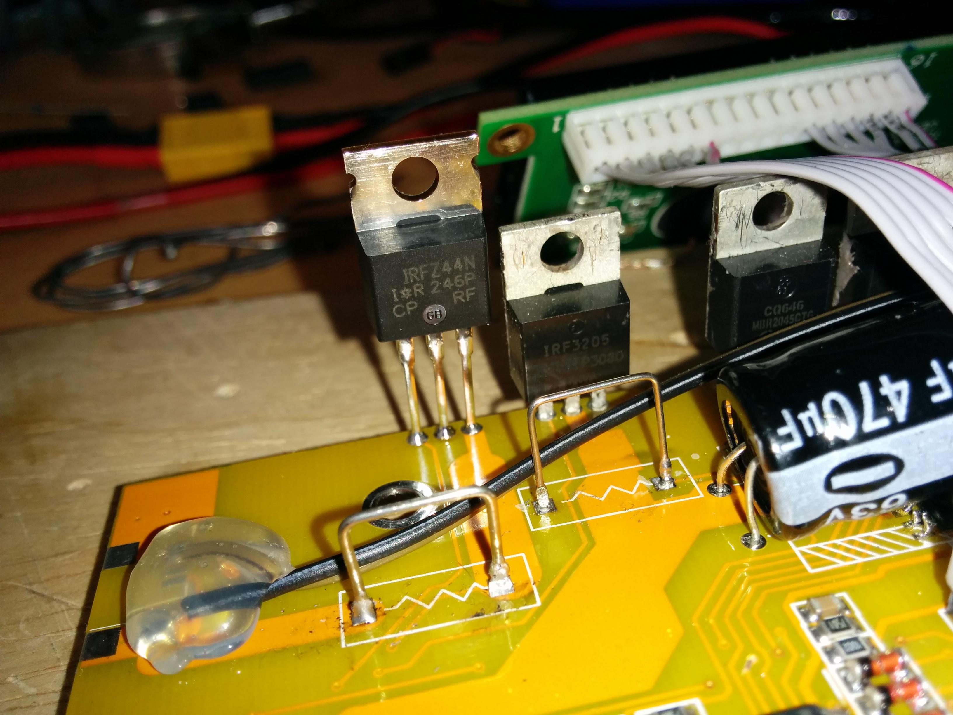
I flashed it with cheali-charger, which worked great, but when I had assembly finished and tried to charge my LiPo, I had a short between the MOSFET (Q20, Q22 on the second page of the wiring diagram) for Bat+ and Bat- (Image attached). Since then I can do everything except charge the battery - discharge, voltage reading, balance port reading works.
I've already exchanged the IRFZ44N but do not want to change more components at the moment as there may be someone who exactly knows which part to swap to make it charge again?
Any help appreciated!
Thanks,
Surroot

Paweł Si
Feb 7, 2015, 9:53:05 AM2/7/15
to cheali-...@googlegroups.com
parts: Q15,Q14,D2,D3,L1,C7 are involved in the charging process.
(also Q22 and R150 - but since discharging is working they should be OK)
please check D2, D3, if they are OK, it's probably Q15,
if you are able to charge small batteries (powers supply voltage is higher then the battery voltage)
and not able to charge batteries with higher voltage then it's probably Q14.
Best Regards,
Paweł
surroot
Feb 7, 2015, 11:52:10 AM2/7/15
to cheali-...@googlegroups.com
Hello Pawel,
thank you for your help!
I've swapped both D2, D3 (one part MBR2045CTG) and Q15 (IRFZ44N), but it still doesn't work. It sends out 0mA but displays sometimes crazy values like 16000mA and jumps around between different values from 0mA up to 3500mA or something. The value always changes, so I think the current reading is somehow broken. Maybe an ADC pin of ATmega32 is damaged?
I try swapping Q14 and try again.
Best Regards,
Surroot
Paweł Si
Feb 7, 2015, 12:59:51 PM2/7/15
to surroot, cheali-...@googlegroups.com
2015-02-07 17:52 GMT+01:00 surroot <philip...@gmail.com>:
Hello Pawel,thank you for your help!I've swapped both D2, D3 (one part MBR2045CTG) and Q15 (IRFZ44N),
Q15 is a P-channel enhancement-mode MOSFET, and IRFZ44N is N-channel enhancement-mode MOSFET!
surroot
Feb 7, 2015, 2:01:33 PM2/7/15
to cheali-...@googlegroups.com, philip...@gmail.com
Oh, oops, so I swapped Q14 first... ^^
I've swapped the other Diodes MBR2045CTG and the P-Channel MOSFET (IRF4905) now, but it still doesn't work.
Current output: 0mA, the display says some strange values...
Thanks!
Paweł Si
Feb 7, 2015, 2:13:12 PM2/7/15
to cheali-...@googlegroups.com
2015-02-07 20:01 GMT+01:00 surroot <philip...@gmail.com>:
Oh, oops, so I swapped Q14 first... ^^I've swapped the other Diodes MBR2045CTG and the P-Channel MOSFET (IRF4905) now, but it still doesn't work.Current output: 0mA, the display says some strange values...
Hm...the current is measured on R150 (through Q22) maybe is damaged after all,
you could also check the elements/voltages near the nearby LM2904 op-amp.
surroot
Feb 7, 2015, 4:02:53 PM2/7/15
to cheali-...@googlegroups.com
My multimeter beeps when I connect it to both R138 and R150.
Actually I don't know what to look for when I check the voltages. VCC seems to be ok on all LM2904, some about 11V some 5V. I've also swapped all LM2904 and LM393, still the same.
What else could me broken, when there comes 0 current to the battery?
The ATmega32 measures the current on ADC pin PA2?
Paweł Si
Feb 7, 2015, 4:33:50 PM2/7/15
to cheali-...@googlegroups.com
2015-02-07 22:02 GMT+01:00 surroot <philip...@gmail.com>:
My multimeter beeps when I connect it to both R138 and R150.Actually I don't know what to look for when I check the voltages. VCC seems to be ok on all LM2904, some about 11V some 5V. I've also swapped all LM2904 and LM393, still the same.What else could me broken, when there comes 0 current to the battery?The ATmega32 measures the current on ADC pin PA2?
Yes, current is measured on pin 35 (PA2 - resistor R154),
if no current is flowing the voltage should be very small on this pin (in mV)
you could also try to reset calibration to default ("options"->"reset default")
surroot
Feb 8, 2015, 5:47:37 AM2/8/15
to cheali-...@googlegroups.com
Hi Paweł
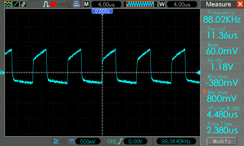
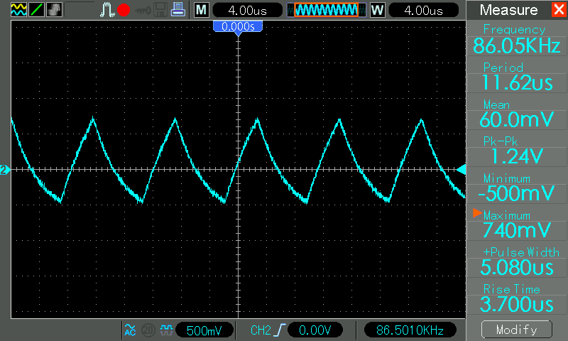
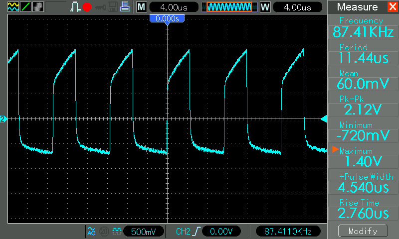
I don't know if its a normal behavior of LM393 4 2/2 to oscillate (measurements attached)?
Anyway, there doesn't seem to get any voltage to the battery. --> The gate of Q15 is high. Shouldn't it be low when the charger wants to charge?
Pin 1 of LM393 3 2/1 is also high, so Q16 is pulling Q15 high, so Q15 is blocking.
Pin 2 is 0V and Pin 3 is oscillating like in picture Pin_6.png.
Because of the difference between the comparator inputs it drives its output high.
Please correct me if anything is wrong.
Thanks!
Paweł Si
Feb 8, 2015, 8:24:37 AM2/8/15
to cheali-...@googlegroups.com
2015-02-08 11:47 GMT+01:00 surroot <philip...@gmail.com>:
Hi PawełI don't know if its a normal behavior of LM393 4 2/2 to oscillate (measurements attached)?
Yes, that's normal, LM393 4 2/2 - is a "jigsaw" oscillator,
and:
Anyway, there doesn't seem to get any voltage to the battery. --> The gate of Q15 is high. Shouldn't it be low when the charger wants to charge?
Q15 should be turned on/off based on the current flow through R150 (based on the signal on "AA") and the "jigsaw" oscillator,
Pin 1 of LM393 3 2/1 is also high, so Q16 is pulling Q15 high, so Q15 is blocking.Pin 2 is 0V and Pin 3 is oscillating like in picture Pin_6.png.
"Pin 2 is 0V" - this is your issue, it should be higher.
In a working charger, the firmware sets a voltage (proportional to the expected output current) on "BB",
this voltage is subcontracted from the actually flowing current on output ("AA" signal) in LM2904 5 2/1
and given to LM393 3 2/1 pin 2.
if output current is 0A, the voltage on "AA" should be low, and on "BB" should be higher then "AA",
what gives a positive voltage on "LM393 3 2/1 pin 2".
There is also LM393 4 2/1 which acts as a "safety valve" (input are on D4,D5,D6), the "safety valve" is activated when:
1. D4 - voltage on BAT+ is too high,
2. D5 - output current is too high (AA, signal too high)
3. D6 - firmware turns off the circuit - charging process ends
surroot
Feb 8, 2015, 10:14:07 AM2/8/15
to cheali-...@googlegroups.com
Well I found the problem:
I had to increase the charge value to ~1700 to get 100mA charge current. I never thought of going that high before because discharge works at a value of about 200.
It starts to charge the battery at 1286 and I've reached exactly 100mA at 1688.
I'm going to swap the components back to the originals and try to charge a 5Ah LiPo with 1C later.
I'm sorry that I've wasted your time Paweł, thank you very much for your help (I've learned a lot about the charging process)!
Best regards.
Paweł Si
Feb 8, 2015, 11:39:40 AM2/8/15
to cheali-...@googlegroups.com
2015-02-08 16:14 GMT+01:00 surroot <philip...@gmail.com>:
Well I found the problem:I had to increase the charge value to ~1700 to get 100mA charge current. I never thought of going that high before because discharge works at a value of about 200.
hmm... the maximum allowed "value" is 32768 this should be near ~7A of output current,
so I'm guessing for 0.1A it should be about 32768/7*0.1 ~= 460 (or less)
~1700 is too high.
your charger has probably a output current measurement problem - R150 has a bigger resistance then it should,
(or some parts values near LM2904 1 2/2 differ).
It starts to charge the battery at 1286 and I've reached exactly 100mA at 1688.I'm going to swap the components back to the originals and try to charge a 5Ah LiPo with 1C later.
I'm sorry that I've wasted your time Paweł,
helping someone is never a wast of time ;)
thank you very much for your help
(I've learned a lot about the charging process)!
nice to hear that!
Best Regards,
Paweł
surroot
Feb 8, 2015, 2:34:32 PM2/8/15
to cheali-...@googlegroups.com
1000mA is reached at about 5400.
When I go to the charge menu and try to charge the battery it says "calibration error I charge".
Tomorrow I'm going to measure R150 if its value is really 0,03Ω. I don't have an mΩ-meter, so I have to unsolder it and measure the current at a voltage.
R151 near LM2904 1 2/2 is a 10k on my PCB instead of 1k.
R152 is an 1k1 instead of 1k.
R153 has 9.85k, should be 10k (maybe of the internals of 1 2/2?).
R154 is 300Ω.
Do I have to edit the cheali sources to accept my charge values?
Paweł Si
Feb 9, 2015, 10:40:28 AM2/9/15
to cheali-...@googlegroups.com
hm... looks better, but still, if 1A is 5400 then 7A will probably be 37800 (to high)
When I go to the charge menu and try to charge the battery it says "calibration error I charge".
it's probably from the wrong R150 resistance.
Tomorrow I'm going to measure R150 if its value is really 0,03Ω. I don't have an mΩ-meter, so I have to unsolder it and measure the current at a voltage.
It's strange that this resistor survived
(If a shunt resistor overheats it can permanently change the resistance of the shunt)
I'm not sure if you will be able to measure it, so I would just check if it looks OK and would add a little more tin to it,
or shorten it a little,
You could however try to measure the voltage drop when charger is running.
R151 near LM2904 1 2/2 is a 10k on my PCB instead of 1k.R152 is an 1k1 instead of 1k.R153 has 9.85k, should be 10k (maybe of the internals of 1 2/2?).R154 is 300Ω.
how to determine the correct parts values, near "LM2904 1 2/2":
1. ADC measures a voltage between 0V-2.5V on pin 35 (PA2 ADC2)
- 0V means no current is flowing
- 2.5V means maximum current (7A)
- the 2.5V limit is set through Vref (pin 29 AREF)
2. R154, R151 are not very important
3. "LM2904 1 2/2" is a non-inverting amplifier, Acl= 1+R153/R152 in your case it's ~= 10
4. so for maximum output current the "LM2904 1 2/2" should have 2.5V/10 = 0.25V on input.
5. in your case: R150 = 0.25V/7A = 0.03Ohm
the exact value of R150 is not very important, as far as it is below 0.035Ohm,
the calibration process will take into account the new resistance.
Do I have to edit the cheali sources to accept my charge values?
no.
surroot
Feb 9, 2015, 1:55:53 PM2/9/15
to cheali-...@googlegroups.com
AREF is exactly 2.5V.
On the input of LM2904 1 2/2 I measure 2.7mV for 100mA charge current and 25.5mV for 1A. So R150 seems to be an 25mOhm resistor.LM2904 1 2/2 has an amplification of 10, so I should get an output of 27mV (100mA charge current) on pin 7. But I actually get 116mV at R154 and ADC2??
Paweł Si
Feb 10, 2015, 6:25:57 AM2/10/15
to cheali-...@googlegroups.com
2015-02-09 19:55 GMT+01:00 surroot <philip...@gmail.com>:
AREF is exactly 2.5V.On the input of LM2904 1 2/2 I measure 2.7mV for 100mA charge current and 25.5mV for 1A. So R150 seems to be an 25mOhm resistor.LM2904 1 2/2 has an amplification of 10, so I should get an output of 27mV (100mA charge current) on pin 7. But I actually get 116mV at R154 and ADC2??
interesting, maybe the LM2904 is damaged?
but you have to take into account that:
1. LM2904 is not a "rail-to-rail" opAmp
(for small output voltage the amplification is different - although 100mV is probably about this limit)
2. it's possible that touching some pins will add noise to the system and all values will be wrong
surroot
Feb 12, 2015, 6:13:29 AM2/12/15
to cheali-...@googlegroups.com
Hey Paweł
I've swapped the LM2904 1 to a new one. Now the 100mA charge calibration value is about 480 and charging works! Thank you!
The only problem I have now is that Q20 (IRF3205) gets really hot when discharging the battery. I know the discharge power has to be dissipated as heat, but it gets really hot. I'm afraid of going over 1A of discharge current. Is there a discharge current limited anywhere in the software?
Do you have a charger where a similar part like Q20 gets that hot?
Best regards,
Surroot
Paweł Si
Feb 12, 2015, 5:18:08 PM2/12/15
to cheali-...@googlegroups.com
2015-02-12 12:13 GMT+01:00 surroot <philip...@gmail.com>:
Hey PawełI've swapped the LM2904 1 to a new one. Now the 100mA charge calibration value is about 480 and charging works! Thank you!The only problem I have now is that Q20 (IRF3205) gets really hot when discharging the battery. I know the discharge power has to be dissipated as heat, but it gets really hot. I'm afraid of going over 1A of discharge current. Is there a discharge current limited anywhere in the software?
It's not about the current but power, in your case the discharge power limit is set to 25W,
without a heat sink the transistor will burn, but with a heat sink I wouldn't worry.
You could change this limit but you would need to recompile the firmware.
Do you have a charger where a similar part like Q20 gets that hot?
all of them :-), on my Power-GT you can't touch the charger after a while
Best Regards,
Paweł
Paweł Si
Feb 12, 2015, 5:21:36 PM2/12/15
to cheali-...@googlegroups.com
The firmware turns off discharging when the chargers temperature gets hotter than 60C,
you could check if the temperature is displayed correctly.
Reply all
Reply to author
Forward
0 new messages