Problem in modelling heat losses along a Plug-Flow Reactor (PFR)

Francisco Mesquita Guimarães
Hi everyone,
I’m developing a model of a stabilized burner for the combustion of ammonia/hydrogen.
My model consists of some Perfectly Stirred Reactors (PSR) and one Plug-Flow Reactor (PFR).
For the modeling of the PFR, I’m using a chain of reactors, as it is done in the example of Cantera’s site (https://cantera.org/examples/python/reactors/pfr.py.html). I also consider heat losses (by conduction and radiation) along the PFR.
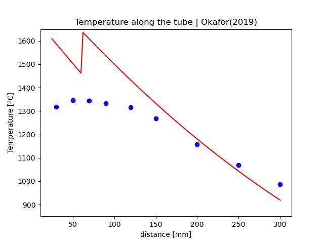
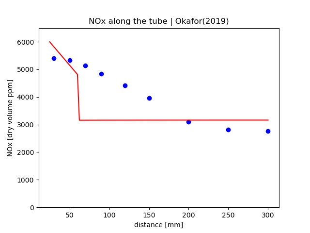
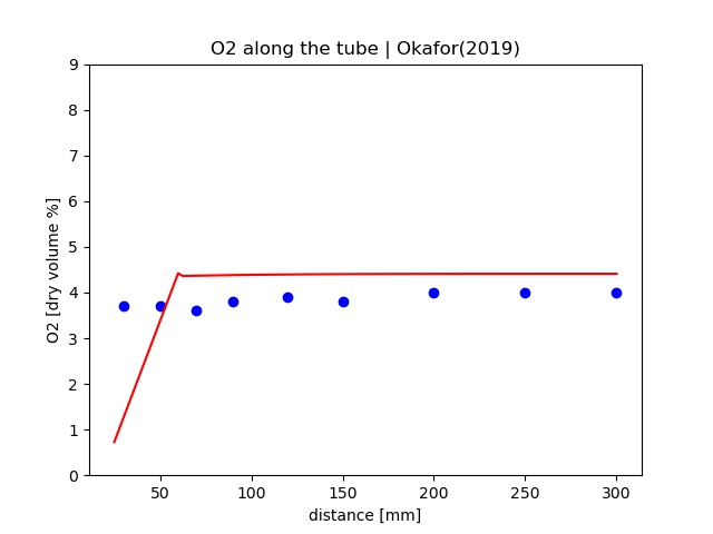
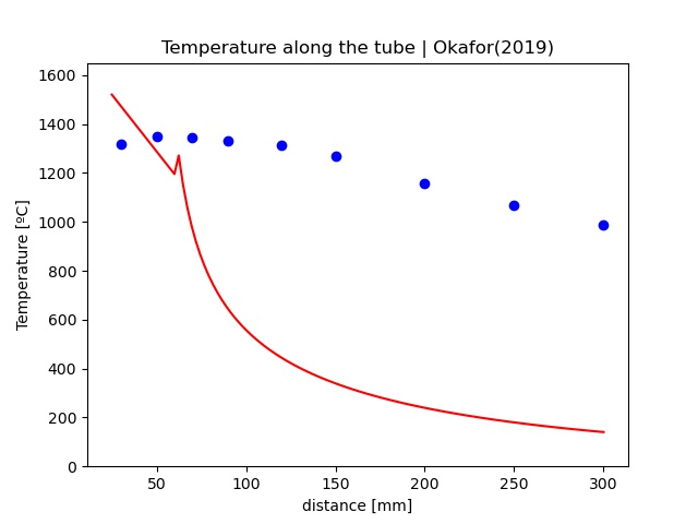
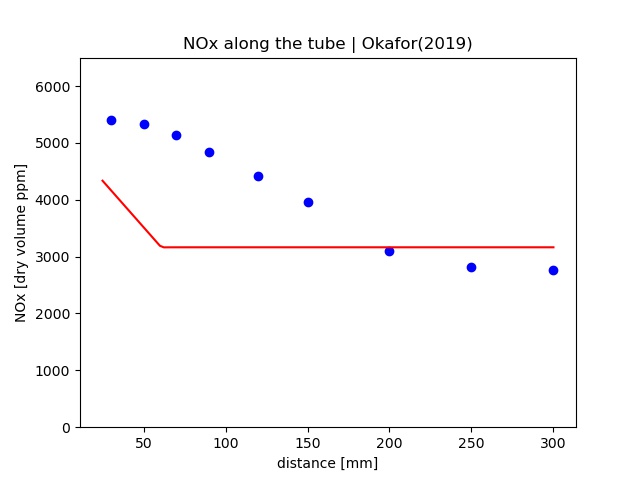
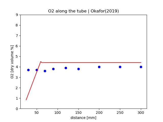
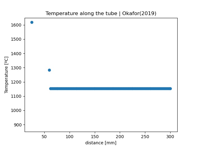
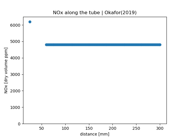
However, despite the heat losses, the temperature and emissions stay constant all along the PFR… And they should decrease through it.
Here are the graphic results and some parts of my code relevant to this issue.
Some previous clarifications:
- PFZ is the PFR
- CRZ is the psr upstream the PFR
- dSurfArea_PFZ is the surface area of each one of the reactors of the chain (PFR)
- the emissivity (emiss_ext) considered is 0.9
- t is 10 seconds, to attain steady state
height_PFZ = height_QT - height_ORZ
crossArea_PFZ = np.pi * intDiameter_QT**2 / 4
vol_PFZ = crossArea_PFZ * height_PFZ
surfArea_PFZ = np.pi * intDiameter_QT * height_PFZ
dLength_PFZ = height_PFZ / nReactors
dSurfArea_PFZ = surfArea_PFZ / nReactors
dVol_PFZ = crossArea_PFZ * dLength_PFZ
wall_PFZ.emissivity = emiss_ext
for n in range(nReactors):
# Set the state of the reservoir to match that of the previous reactor
gas.TDY = PFZ.thermo.TDY
CRZ.syncState()
# integrate the reactor forward in time until steady state is reached
# sim.reinitialize()
sim.set_initial_time(0.0)
# sim.advance_to_steady_state()
sim.advance(t)
# output data
resTime_PFZ[i, j, a, b, c] += PFZ.mass / mdotGas_CRZ_PFZ[j]
states_PFZ.append(PFZ.thermo.state, tres=resTime_PFZ[i, j, a, b, c])
dist = np.hstack([dist, dist[-1] + dLength_PFZ])
Temp_predicted = np.hstack([Temp_predicted, PFZ.T])
wmf_NOx = states_PFZ.X[:, gas.species_index('NO')][-1] + states_PFZ.X[:, gas.species_index('NO2')][-1]
wmf_H2O = states_PFZ.X[:, gas.species_index('H2O')][-1]
dmf_NOx = wmf_NOx / (1 - wmf_H2O)
NOx_predicted = np.hstack([NOx_predicted, dmf_NOx])
wmf_O2 = states_PFZ.X[:, gas.species_index('O2')][-1]
wmf_H2O = states_PFZ.X[:, gas.species_index('H2O')][-1]
dmf_O2 = wmf_O2 / (1 - wmf_H2O)
O2_predicted = np.hstack([O2_predicted, dmf_O2])


Steven DeCaluwe
<temperature_along_tube.jpeg><NOx_along_tube.jpeg><O2_along_tube.jpeg>
Does anyone have any idea what mistake I am making in modelling heat losses along PFR?Thank you very much in advance!Francisco
--
You received this message because you are subscribed to the Google Groups "Cantera Users' Group" group.
To unsubscribe from this group and stop receiving emails from it, send an email to cantera-user...@googlegroups.com.
To view this discussion on the web visit https://groups.google.com/d/msgid/cantera-users/d1a2c767-63b6-4a76-a16f-7d160c22ad67n%40googlegroups.com.
<NOx_along_tube.jpeg><temperature_along_tube.jpeg><O2_along_tube.jpeg>
Francisco Mesquita Guimarães
T0_air = 298
T0_fuel = 298
T0_intQT = 298
fuel = ct.Solution('Okafor(2019).cti')
fuel.TPX = T0_fuel, P, 'NH3:{:.2f}, H2:{:.2f}'.format(xNH3, xH2) # to change the fuel composition
rhoFuel = fuel.density
M_fuel = fuel.mean_molecular_weight
# gaseous oxidizer
air = ct.Solution('Okafor(2019).cti')
air.TPX = T0_air, P, 'O2:{:.2f}, N2:{:.2f}'.format(xO2, xN2)
rhoAir = air.density
M_air = air.mean_molecular_weight
# initial mixture inside reactors (air)
gas = ct.Solution('Okafor(2019).cti')gas.set_equivalence_ratio(phiPri[j], 'NH3:{:.2f}, H2:{:.2f}'.format(xNH3, xH2),'O2:{:.2f}, N2:{:.2f}'.format(xO2, xN2))
gas.TP = T0_intQT, P
rhoGas = gas.density# Create reservoirs for the two inlet streams
resAir = ct.Reservoir(air)
resFuel = ct.Reservoir(fuel)
Steven DeCaluwe
To view this discussion on the web visit https://groups.google.com/d/msgid/cantera-users/745196bb-c21d-4bfd-928b-eaacd6664cd5n%40googlegroups.com.
Francisco Mesquita Guimarães