Definitive thread on Floppy Repair?

greg christie
I’ve had a Cat for a few years - after reading about the floppy issues I’ve just left the one floppy in it.
I’m thinking about doing the needed floppy repair soon. About every six months or so I go through this group looking for documentation on how to do the repair but never seem to find anything definitive.
Are there clear instructions somewhere that I can never find?
Thanks in advance

dwight
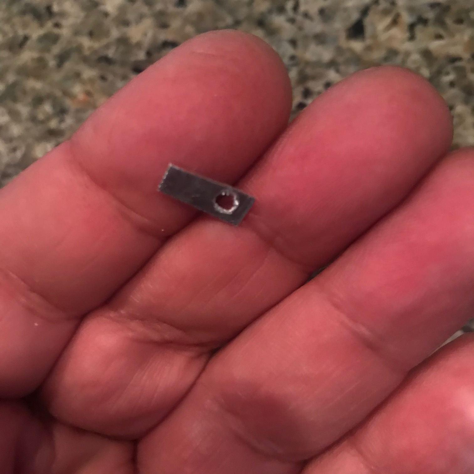
I think Rubin has some pictures of the drive apart. I don't know if we have anything on getting the drive out. What fails is the clamp for the guide rail. It is a piece of nylon that was over stressed in the assembly. Nylon ages and become brittle and it cracks. In a few cases, I've seen it is just getting ready to fail. In others the tip has completely broken off.
What happens then is it lifts up at the back end when the disk is ejected. The being towards the front tilts down and catches on the floppies case. If forced, by pulling hard on the disk, one rips the head off, making the drive useless.
I replaced the piece with a tougher piece of plastic on mine. Jack just used some JB Weld epoxy to hold it down. Either way would work but be sure to limit where the epoxy goes. The heads guide slides really close the where the piece of nylon was.
As I recall disassembling the case is a pain. One will want to also remove the keyboard. I recommend loosening the main board by the screws on the bottom so you can get at the front of the board. You'll be able to access where the keyboard connects to the main board easier. The drive has a ribbon cable permanently attached but the board end uses a IDC type header connector. These are really hard to get loose and sometimes it is easier to loosen the side of the main board, with the floppy bracket loose first, to unconnect it. It is much harder to reach through the hold and one could easily pull the IDC of the ribbon apart from above.
Once you have the drive out, you can remove it from the drive bracket mount.
Pop the cover off and then you need to disassemble the top piece. As I recll, you can slide it forward some and the 4 pins will release it. Note how the eject spring works. As I recall, one has to hold it back while putting the top piece back in. With the top piece out of the way, you can see the back end of the head guide rail.
You'll find attaching the cable for the keyboard is much easier with the main board dropped down a litttle. It is one of the flex cable connectors and is solidly attacked at the keyboard end.
While you have things loose, is a good time to replace the coin cell for the CMOS RAM. I recall it is either a 2032 or a 3032 in a holder, towards the front of the main board.
Dwight
Sent: Thursday, February 20, 2020 9:55 AM
To: Canon Cat <cano...@googlegroups.com>
Subject: [Canon Cat] Definitive thread on Floppy Repair?
You received this message because you are subscribed to the Google Groups "Canon Cat" group.
To unsubscribe from this group and stop receiving emails from it, send an email to canon-cat+...@googlegroups.com.
To view this discussion on the web visit https://groups.google.com/d/msgid/canon-cat/f7ef8949-64f7-43df-87ae-909d1f51036c%40googlegroups.com.

Charles Springer
To view this discussion on the web visit https://groups.google.com/d/msgid/canon-cat/BYAPR01MB5608E1F21BE787C25A3186F0A3130%40BYAPR01MB5608.prod.exchangelabs.com.
dwight
Delrin is nylon with some teflon mixed in. It gets brittle with age, like nylon does.
A small metal spring would be best. There are two holes to locate the piece. One hole has a pin that goes through the mounting and the nylon is staked there. The other hole has a screw to clamp it to the mounting.
The best would be a small piece of spring metal ( not steel though ) with a hole for the screw and a dimple to locate in the hole.
A delrin piece might still work but it doesn't need to be mounted flat to the mounting. It looks like the original design was that the screw would be tightened just enough to hold the guide rod. Someplace in the manufacturing flow, it must have change to completely tightened. This puts a lot of stress on the nylon finger that holds the rod.
The piece is quite small and would be a challenge for most 3D printers. The original looks to be injection molded.
Dwight
Sent: Thursday, February 20, 2020 11:49 AM
To: cano...@googlegroups.com <cano...@googlegroups.com>
Subject: Re: [Canon Cat] Definitive thread on Floppy Repair?
Charles Springer
To view this discussion on the web visit https://groups.google.com/d/msgid/canon-cat/BYAPR01MB5608E16C58EF28EE40B47DE3A3130%40BYAPR01MB5608.prod.exchangelabs.com.
dwight
Dwight
California Electric
I think I need to see the mechanism to truly understand it all. I’ll post pics so this can get documented moving forward.
Hope to dig into it next week.
California Electric
Will post pics as soon as I figure out how - it doesn’t look like the mobile version of google groups lets you.
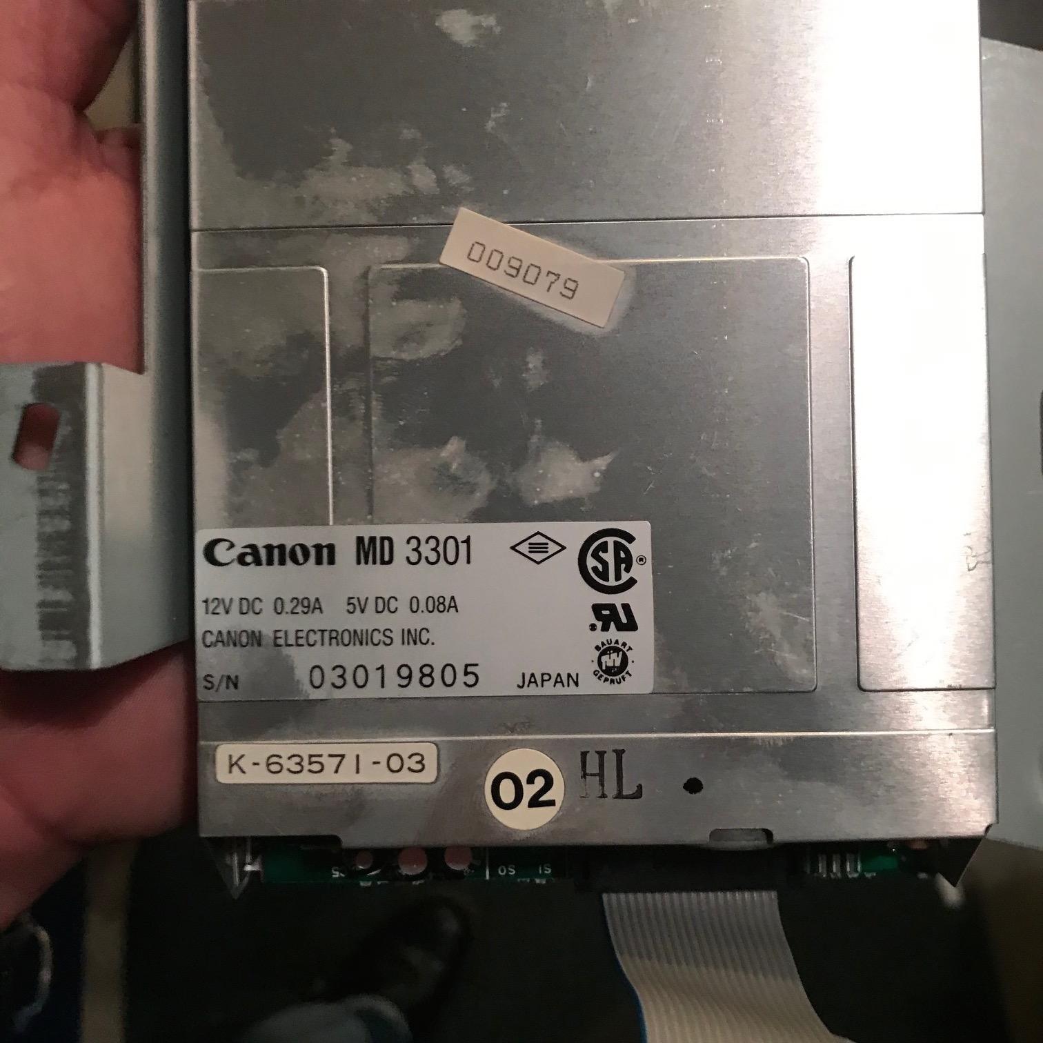
I got access to the FDD by:
1 - invert cat on towel on workspace.
2 - remove 5 screws on bottom pan
3 - gently ease up one edge of pan giving access to the three cable connections. Watch the connectors at the rear of the cat.
4 - gently remove white flex cable from logic board
5 - ease the pan and logic board side over side from the edge without cable connection (visualize the two remaining cables as a hinge). Continue to hold the side of the pan with one hand as you remove the two cable connections. Note the direction of the 9 pin heavy header. Yes it’s keyed with a missing pin, but why risk bending anything.
6 - put pan aside.
NOTE - the FDD is NOT on a flex cable, at least not on my cat. It’s a standard ribbon cable. It’s captive on the floppy side but just a standard 20-pin IDC connector and header on the logic board side. This bodes well for making an adaptor cable for a floppy emu later. The flex cable is for the keyboard.
7 - roll the cat right side up.
8 - remove 4 screws from rear of cat. Two are mildly hidden in the handle area.
9 - Set aside rear case.
10 - remove three screws securing FDD bracket to frame. Note the larger screw is in the lower forward position.
11 - Ease the bracket with FDD off of the cat, being careful not to scrape the cable on the sharp edge of the frame cutout.
NOTE - either the insulation on the cable in the area where it passes through the frame should be reinforced OR the sharp edges of that cutout should be taped. My cable shows some evidence of abrasion in that area.
12 - Set aside cat
13 - Remove four screws holding FDD to bracket. On mine two opposite corners were thread locked - be careful not to strip the soft metal screw heads.
14 - Set aside bracket
Now you have the FDD with captive cable.
More to follow.
California Electric
Also it's possible to get at the floppy just by removing the four screws on the back and pulling the back case, but the header for the floppy is directly under a cutout in the frame, and surrounded by a few caps, so it might be easy to slice your fingers on the frame metal. By dropping the pan and logic boardyou have much better access to the cable end without sharp metal around it.
California Electric
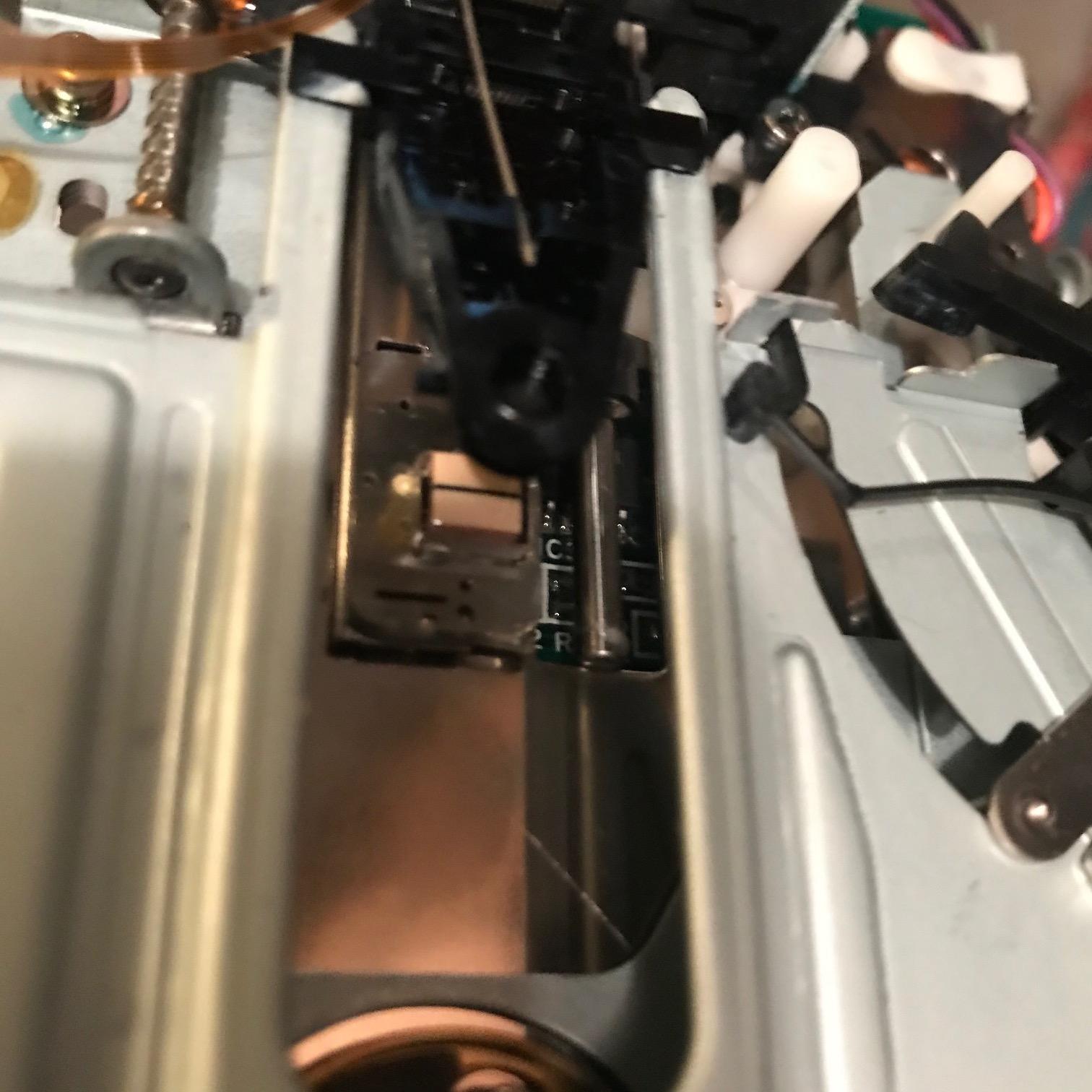
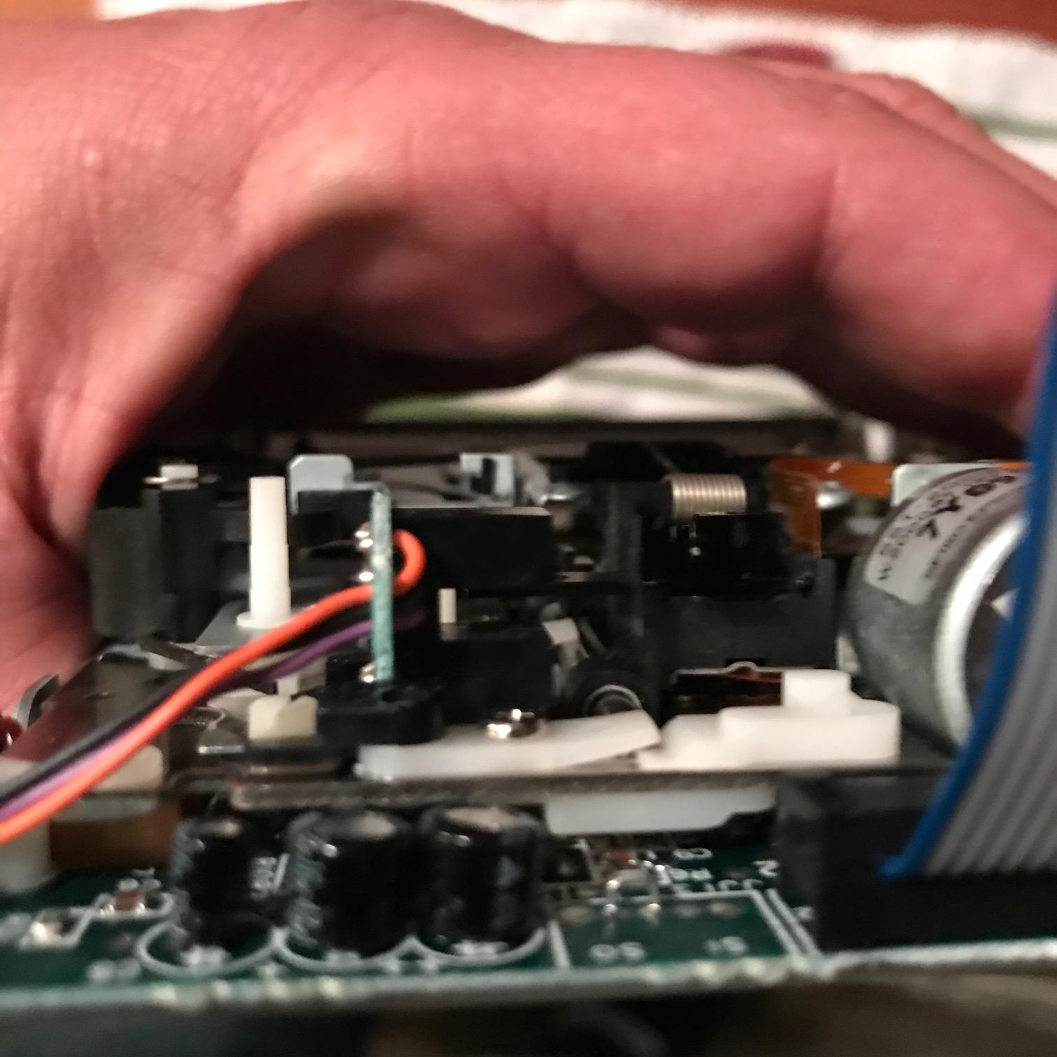
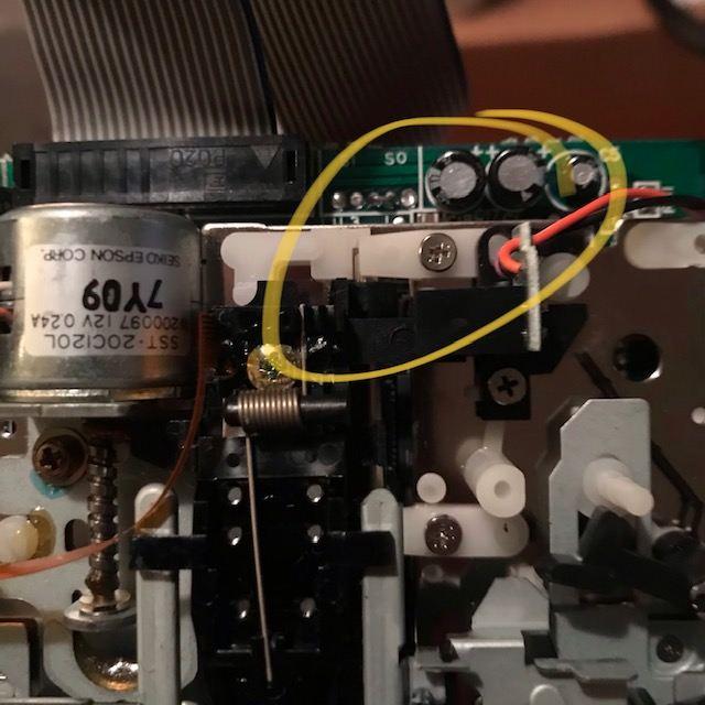
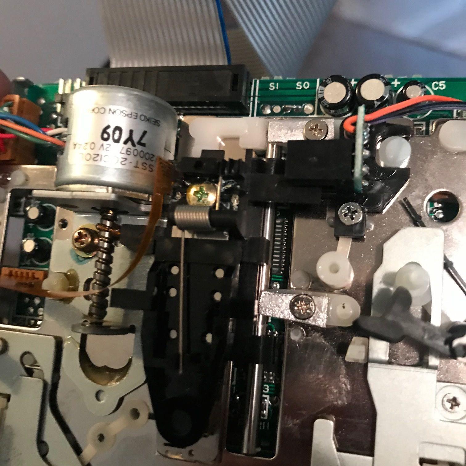
You can see it, just to the right of the head. There seems to be a bit of excess lubricant right on the end of the rod, but it's interesting to see that rod is not secured at that end in any way.
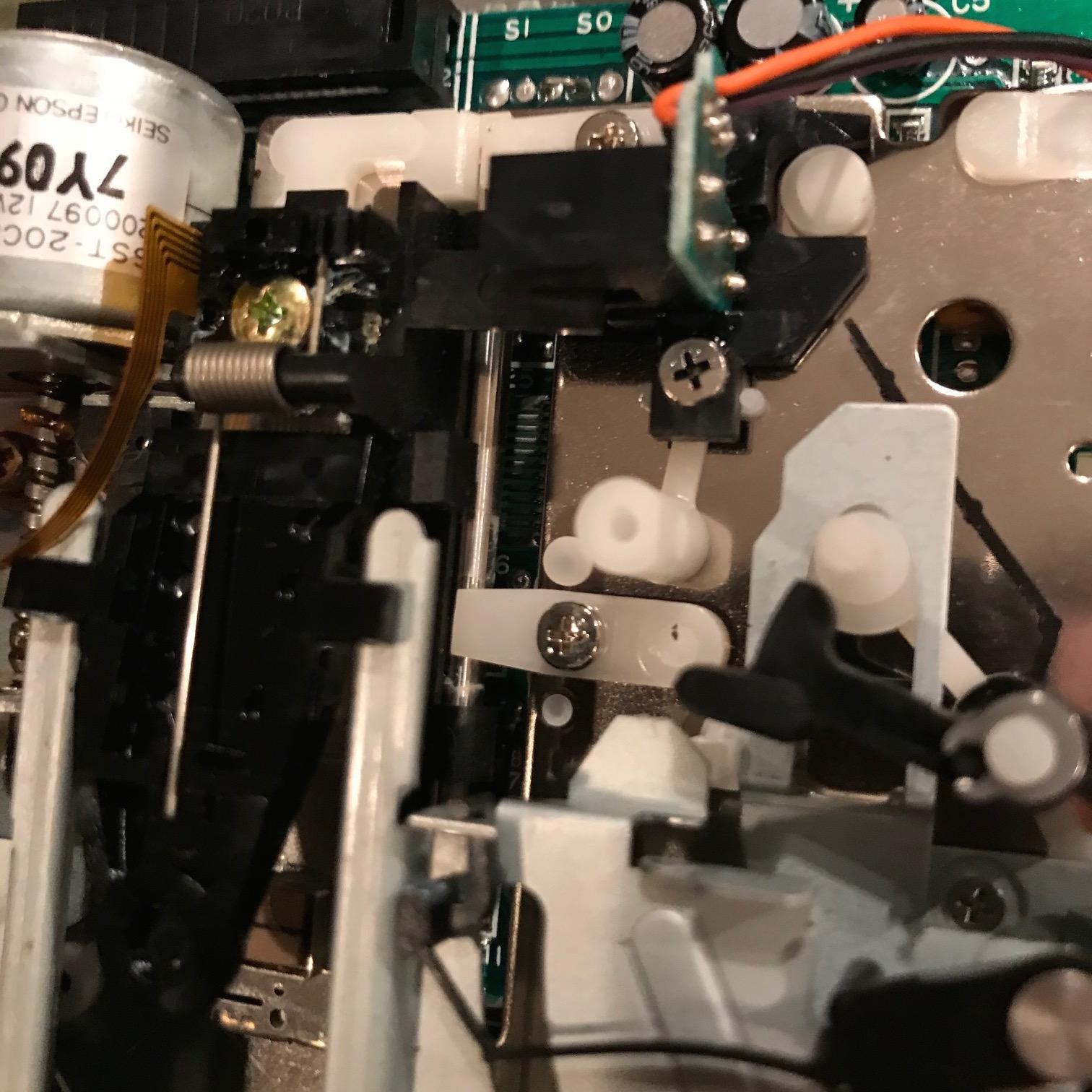
Nearest the top of the picture, just below the three caps, with the shiny screw, and seems to share mounting with the optical interrupter for track 0. Here's a slightly out of focus view from the back of the drive, showing the angle, and how it overlaps the double L shaped piece of identical material:
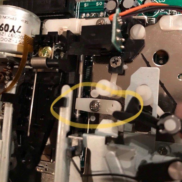
So, Is that the tab that breaks and lets the guide rod shift? If so, what is the goal of the application of epoxy? Are we trying to fix the rod in place? Or trying to reinforce that plastic tab? Am I trying to loosen that tab, apply epoxy in the gap formed by the tilt and overlap and retighten? Epoxy across the top of the two nylon parts effectively tying them together into one piece and reinforcing the top part? All of the above? It looks like there is just enough room to do this while allowing full travel of the head along the rod. This is very slippery nylon like plastic and typically epoxy does not bond well to stuff like this. I can use a scalpel and micro file to roughen the surfaces to hopefully give the epoxy more grip. I agree with the others who think this assembly stinks. I would so much rather have metal circular retainers on BOTH ends of the rod, secured to the frame by screws.
Please let me know if I've identified the correct part (there's no visible evidence of a crack yet), and provide any input you have with regard to what to epoxy, etc...
dwight
Sent: Saturday, February 22, 2020 12:31 AM
To: Canon Cat <cano...@googlegroups.com>
Subject: Re: [Canon Cat] Definitive thread on Floppy Repair?
You received this message because you are subscribed to the Google Groups "Canon Cat" group.
To unsubscribe from this group and stop receiving emails from it, send an email to canon-cat+...@googlegroups.com.
California Electric
California Electric

Or this, at the back end of the guide rod:

It seems from the previous threads that folks are talking about the one in the second photo, at the back of the guide rod. But in the 2017 thread, "New Cat Repairs" by Marcin Wichary it seems that the tab at the back end is fine, but the tab in the middle of the guide rod is what snapped.
Thanks for any and all advice and details....
dwight
To: Canon Cat <cano...@googlegroups.com>
Subject: Re: [Canon Cat] Definitive thread on Floppy Repair?
You received this message because you are subscribed to the Google Groups "Canon Cat" group.
To unsubscribe from this group and stop receiving emails from it, send an email to canon-cat+...@googlegroups.com.
California Electric
Both have shiny screws going through them.
Thanks again!
California Electric
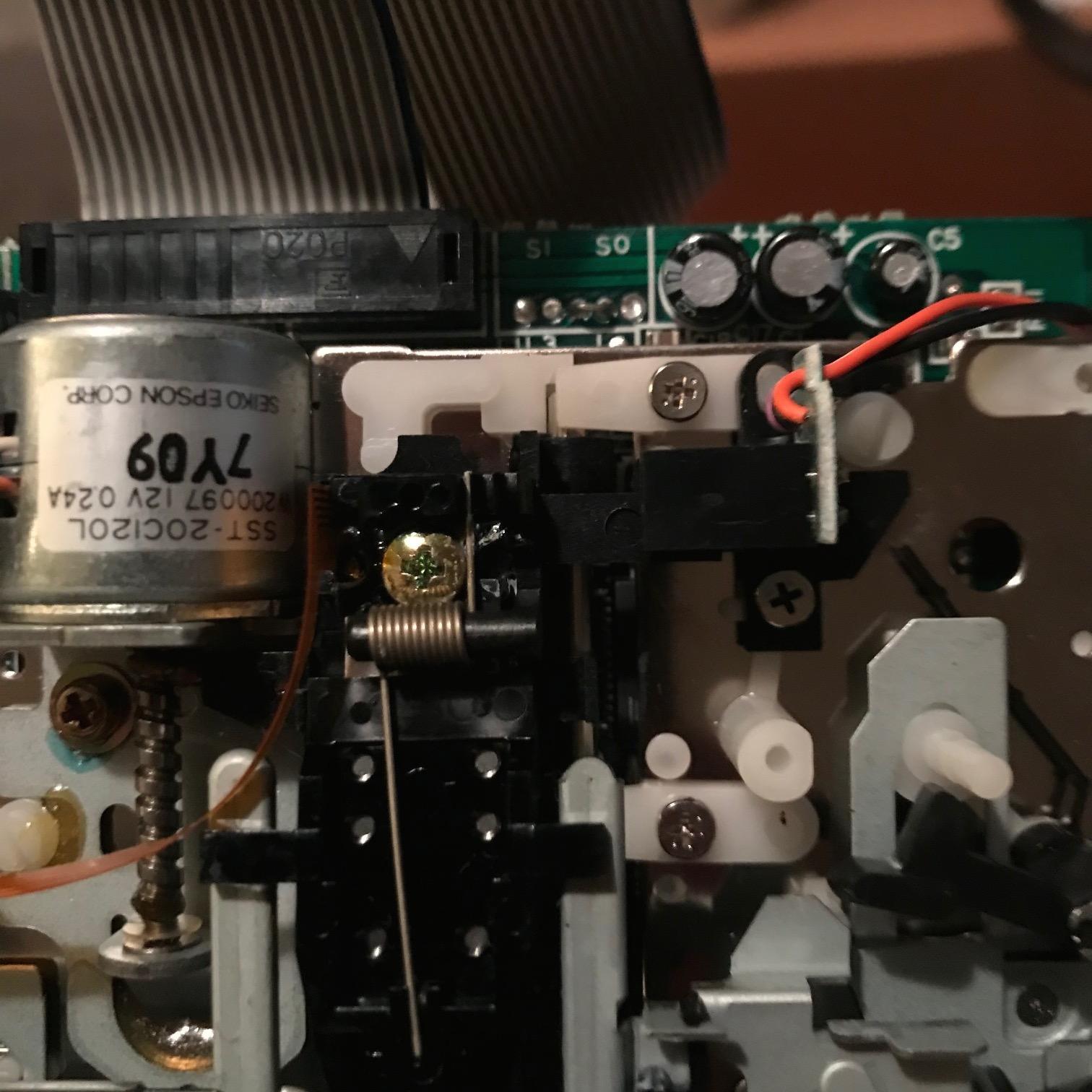
I used industrial CA as a bonding agent to secure the nylon tab to the metal frame they rest on, and some more on the top of the tabs to laminate them to the aluminum straps. The aluminum stock was think enough so that I could use the existing crews to secure them
Here they are installed:
The straps don't interfere with the drive head assembly or any other mechanisms, and clear the guide rod completely.
I've tested the drive with two separate floppies. All good so far (knock wood).
With the straps in place, I am considering a bead of epoxy across the top to provide extra mass and further rigidity to the reinforced tabs.
To finish out the disassembly steps:
16 - Release the spring wires from the left and right sides of the drive.
17 - Remove the large spring from the top of the drive
18 - jiggle the top tray forward and back a bit, trying to clear the black plastic catches and arms.
19 - remove screw and the black plastic block on the right, near the black hook shaped part and the pivot for the metal arm (where you removed the large spring). Note that the block is mounted both insde and outside the frame of the drive. It will need to go back exactly the same way.
20 - jiggle the top tray forward and back a bit, the pins on the sides need to come out of the slots, at the time that the central U shaped "fork" needs to slide out of the drive head assembly.
21 - Repair or reinforce the plastic tabs securing the guide rod as you see fit.
Reassembly is the reverse of the first 20 steps.
Thanks all. Hope this description shows up in Google for the next person who needs to repair or protect their Cat.