Fun with threads (and non-manifold results)
784 views
Skip to first unread message

Neal Nelson
May 15, 2020, 12:22:26 PM5/15/20
to CadQuery
Since I can't yet get OCP to compile on FreeBSD, I've been continuing to tinker on my Mac that seems to work (mostly). I've been trying to generate threads, with some success. I initially used the process in the famous gist (https://gist.github.com/fragmuffin/266bee4babd9a25aea2d53c739144ee3), although this didn't work, but after following the FreeCAD tuotrial, which used the same process, I finally got a nice, if somewhat computationally expensive, thread.
I put my finished object into a slicer and was told that my object was non-manifold.
So, I have been trying various other options. Instead of sweeping the cross section of a thread, I decided to just sweep the profile and cut this from a cylinder. This doesn't work and results in an immediate crash. If the swept thread profile starts below the cylinder from which it's being cut, it crashes. It can however go beyond, so the top looks OK. Unfortunately this results in a non-maifold solid.
After much playing, I have found that if the swept profile is contained completely within the object that it's being cut from, all is well. If the cut goes above the object, the result is non-maifold. If the top or bottom of the object is later cut off, the result is non-manifold.
I hope this all makes sense. Here's some test code showing the problem:
wire = cq.Wire.makeHelix(pitch, height, radius)
cut_path cq.Workplane("XY").newObject([wire]).translate((0, 0, pitch))

profile = (
    cq.Workplane("XZ")
    .polyline(profile_points)
    .close()
    .sweep(cut_path, isFrenet=True)
)

body = (
    cq.Workplane("XY")
    .circle(radius)
    .extrude(height+pitch)
)

result = body.cut(profile)
This results in a cylinder that's threaded almost to the ends, but not quite. It's manifold.
Now if I either extend the cut profile to go beyond the top of the cylinder so that it makes a proper thread, this results in a non-manifold object. Likewise if I cut off the bottom part, it also becomes non-manifold.
So, my question is; is this how it's supposed to work? Am I doing doing somethign silly, or is it a bug? Obviously the crashes I get are bugs.

Jeremy Wright
May 15, 2020, 1:03:47 PM5/15/20
to CadQuery
It sounds like a kernel issue.
If you'll post sample values for the variables (pitch, profile_points, etc), I'll give it a try with the OCP branch and OCCT 7.4.x to see if I get a viable STL out.
Neal Nelson
May 15, 2020, 1:22:42 PM5/15/20
to CadQuery
That doesn't sound good. Let's hope it's not an insurmountable problem.
Here are my test values:
pitch = 6
depth = 3
radius = 20.0
height = 20.0

profile_points = (
    (radius+depth, 0.1),
    (radius+0.1, 0.1),
    (radius-depth, pitch/2),
    (radius+0.1, pitch+0.1),
    (radius+depth, pitch+0.1)
)
I've been generating AMF files rather than STLs as the output seems better, but I get the same results when I generate an STL.
Just out of interest: what other formats are supported? I can't find any documentation, so I had a dive in the code and only found STL, AMF, STEP and a json format.
Jeremy Wright
May 15, 2020, 2:06:12 PM5/15/20
to CadQuery
Here's the list of export formats. https://github.com/CadQuery/cadquery/blob/master/cadquery/occ_impl/exporters.py#L31
Our export capability needs some improvement, and there's work slowly being done in that direction: https://github.com/CadQuery/cadquery/issues/216
Can you send me the parameters you're using to make a non-manifold model?
Neal Nelson
May 15, 2020, 2:55:01 PM5/15/20
to CadQuery
If you change the first line to the following:
wire = cq.Wire.makeHelix(pitch, height+pitch, radius)
The threading will go all the way off the top of the cylinder, but it will no long be manifold, even though it looks OK. At least the exported object won't be manifold.
Jeremy Wright
May 15, 2020, 3:30:19 PM5/15/20
to CadQuery
The following code, executed in the pre-built version of CQ-editor, RC2 in Ubuntu 18.04, exports an STL that opens and slices fine in PrusaSlicer 2.2.0. It doesn't look like there's a Mac release of RC2, so you may be forced to run RC1, but there was a bug in CadQuery in that version that caused helix heights to be incorrect. If you try RC1, use height+pitch*16 in the line you posted to make sure the helix goes high enough.
import cadquery as cq

pitch = 6
depth = 3
radius = 20.0
height = 20.0

profile_points = (
    (radius+depth, 0.1),
    (radius+0.1, 0.1),
    (radius-depth, pitch/2),
    (radius+0.1, pitch+0.1),
    (radius+depth, pitch+0.1)
)
#wire = cq.Wire.makeHelix(pitch, height, radius)
wire = cq.Wire.makeHelix(pitch, height+pitch, radius)
cut_path = cq.Workplane("XY").newObject([wire]).translate((0, 0, pitch))
profile = (
    cq.Workplane("XZ")
    .polyline(profile_points)
    .close()
    .sweep(cut_path, isFrenet=True)
)

body = (
    cq.Workplane("XY")
    .circle(radius)
    .extrude(height+pitch)
)

result = body.cut(profile)
result.val().exportStl('/home/jwright/Downloads/test_stl.stl', precision=0.001)

show_object(result)
Neal Nelson
May 17, 2020, 10:04:05 AM5/17/20
to CadQuery
OK, some background is needed: I initially modelled a jar lid with an internal thread, and all looked nice, but when I tried it in the PrusaSlicer it filled it all in, instead of being hollow. I tried it in the cura slicer and this told me that the shape was not manifold. It seemed to handle the shape better and sliced it correctly even though it wasn't happy. This suggests to me that the PrusaSlicer doesn't check whether a shape is manifold and therefore produces unpredictable results.
So, with this in mind, as suggested I extended my cutting helix complety above the cylinder I was cutting the thread from and this, to my amazement, produced a manifold shape. Flushed with success I then extended the helix to well below my cylinder and to my surprise it didn't crash, but I did get the following rather strange error: "Standard_Failure Courbes non jointives". This looks like French to me, although I have no idea why I might be getting French error messages, not what it means.
For a laugh I converted the threaded neck part of the OCC bottle tutorial into python and imported the resulting shape into cadquery, which looked really nice. Alas this is also not manifold, but it does offer an alternative method to making threads that is really fast, but also quite complex. If I could get this to generate a manifold thread, it might make a nice utility.
So, the only reason I'm worried whether the threads come out as manifold is because slicers either get confused or whinge about it if it's not. To me this highlights a deeper problem, but that may be in OCCT itself.
Jeremy Wright
May 17, 2020, 11:10:11 AM5/17/20
to CadQuery
Can you post the jar lid that wasn't manifold? I'll try it with OCCT 7.4.x and then check in Cura.
Neal Nelson
May 17, 2020, 12:27:36 PM5/17/20
to CadQuery
Here's the code that produces the "interesting" results when sliced:
import cadquery as cq

def _helical_path(pitch, height, radius):
    """
    Make a helix on the XY plane, growing in Z.
    """
wire = cq.Wire.makeHelix(pitch, height, radius)
    return cq.Workplane("XY").newObject([wire])

def make_thread(pitch, radius, height, profile_points):
    """
    Make a solid threaded object.

    :param pitch: Thread pitch.
    :param radius: Thread radius.
    :param height: Thread height.
    :param profile_points: Sequence of X,Y tuples defining the *inverse* of the profile profile.
    :returns: CQ.Solid
    """

    single_turn = _helical_path(pitch, pitch, radius)
    profile = (
        cq.Workplane("XZ")
        .polyline(profile_points)
        .close()
        .sweep(single_turn, isFrenet=True)
    )

    cross_section = (
        cq.Workplane("XY")
        .workplane(offset=-pitch / 2.)
        .circle(radius)
        .extrude(pitch / 2.)
        .cut(profile)
        .faces(">Z")
    )

    cross_section_face = cross_section.val() # cadquery.Face
    cross_section_wire = cross_section_face.Wires().pop()

    full_helix = _helical_path(pitch, height, radius)

    result = cq.Workplane("XY").newObject([cross_section_wire])
    result._addPendingWire(cross_section_wire)
    result = result.sweep(full_helix, isFrenet=True, multisection=False).combine()

    return result

lid_thickness = 2
lid_height = 20 - lid_thickness
lid_radius = 54.5 - lid_thickness

cylinder = (
    cq.Workplane("XY")
    .circle(lid_radius)
    .extrude(lid_height)
)

pitch = 5
thread_radius = lid_radius
thread_height = lid_height + 2

points = (
    (thread_radius+0.1, 0),
    (thread_radius-pitch, pitch/2),
    (thread_radius+0.1, pitch)
)

torus = cq.Solid.makeTorus(
    32, 12,
    pnt=cq.Vector(0,0,lid_height),
    dir=cq.Vector(0,0,1),
    angleDegrees1=0,
    angleDegrees2=360
)

lid = cylinder.cut(torus)
lid = lid.faces("-Z").shell(lid_thickness)

tap = make_thread(pitch, thread_radius, thread_height, points)
tap = tap.translate((0, 0, -1))

thread_cylinder = (
    cq.Workplane("XY")
    .circle(thread_radius+(lid_thickness/2))
    .extrude(lid_height)
)

thread_cylinder = thread_cylinder.cut(tap)
lid = thread_cylinder.union(lid)

if __name__ != "__main__":
    show_object(lid)
else:
    print("Exporting...")
    with open("biscuit_lid.amf", "wb",) as outfile:
        cq.exporters.exportShape(lid, cq.exporters.ExportTypes.AMF, outfile)

Eddie Liberato
May 18, 2020, 12:18:53 AM5/18/20
to CadQuery
Funny coincidence that I recently posted on my blog (https://eddieliberato.github.io/) about threads in cq. I'm having some success with external threads but not so much with internal threads. Would be nice to hear about the different approaches to this problem from the community.
@neal nelson, I took a look on your code and apparently the cut() after the shell() was the problem. An alternative approach (I posted below) seems to return a watertight model. This goes in accordance with some recent observations of mine, that union() seems more "robust" than cut(). Is it only my impression ? What you guys think ? If so, it would be better to extrude a negative thread and paste it to the body for internal threads as well.
# modifications begin
thread_cylinder = (
    cq.Workplane("XY")
    .circle(lid_radius+lid_thickness)
    .extrude(lid_height+lid_thickness)
)

thread_cylinder = thread_cylinder.cut(tap)
thread_cylinder = thread_cylinder.union(torus) .\
    faces(">Z[-2]").split(keepTop=False, keepBottom=True) .\
    faces(">Z").workplane().circle(32+12).circle(32-12).cutBlind(-lid_thickness) .\
    edges(">Z").fillet(lid_thickness-0.1)

show_object(thread_cylinder)

# modifications end

#lid = thread_cylinder.union(lid)

#if __name__ != "__main__":
#    show_object(lid)
#else:
#    print("Exporting...")
#    with open("biscuit_lid.amf", "wb",) as outfile:
#        cq.exporters.exportShape(lid, cq.exporters.ExportTypes.AMF, outfile)
te o código aqui...
Adam Urbanczyk
May 18, 2020, 12:08:48 PM5/18/20
to CadQuery
@Neal I tried your code with STL export and neither FreeCAD nor Meshlab complain. AMF export might have issues on the OCP branch (the tesselation function to be specific).
@Eddie cool examples!
Jeremy Wright
May 18, 2020, 3:04:56 PM5/18/20
to cadq...@googlegroups.com, adam.jan....@gmail.com
I did the export of the biscuit lid in both AMF and STL. The AMF file has the weird artifact that closes off the bottom of the lid, and the STL looks correct.
Jeremy Wright
May 18, 2020, 3:11:55 PM5/18/20
to CadQuery
And that's on master, not the OCP branch.
Neal Nelson
May 19, 2020, 6:00:35 AM5/19/20
to CadQuery
I tried exporting to STL and it's still reported as non-manifold, but the main reason I'm not using STL is that it looks rubbish with a round object. Also I still get the lid filled in with the PrusaSlicer with STL.
I've tried so many diferent variations now that frankly I've lost track, all in order to work around failure cases. Who would have thought that such a simple object would tax the system beyond it's capabilities. I'm glad I chose it as my way of learning cadquery as it's definitely been informative. Unfortunately though I still don't have a slicable lid, although my earlier efforts using FreeCAD seem to slice OK.
Neal Nelson
May 19, 2020, 6:02:36 AM5/19/20
to CadQuery
This is roughly the same method I started with, but unfortunately there's a feature missing as there needs to be a toroidal indent on the top. As soon as that's added the fillet no longer works, which is why I changed to using a shell, as I got the filleting for free and it worked with the indent.
Adam Urbanczyk
May 19, 2020, 4:11:56 PM5/19/20
to CadQuery
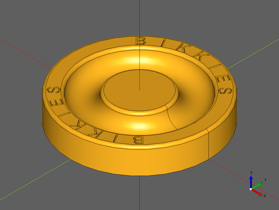
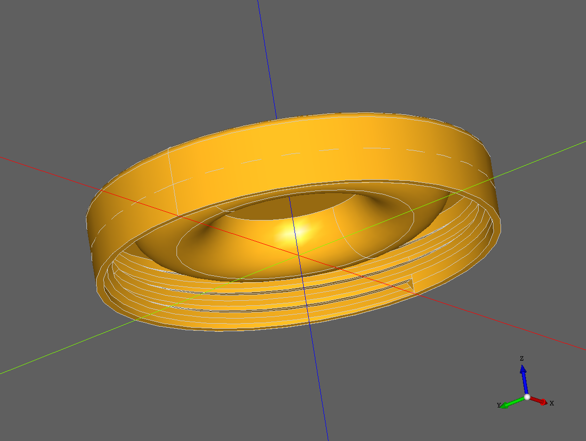
I'm on OCP branch (note that I just exposed angular tolerance of the exportStl function) and the following codes works (i.e. mesh analysis in FreeCAD finds no issues). For some (more aggresive) parameters FreeCAD could find self-intersections on the thread part, but they were fixable. Could you confirm that this works for you? The issue you are seeing might be very well not CQ related. You are saying that STL looks rubbish, but note that AMF uses the same meshing algorithm of OCCT (though likely with different settings). So there is not intrinsic difference between them. I also attach a screenshot of the mesh, I don't see any rubbishy things:
thread_cylinder = (
    cq.Workplane("XY")
    .circle(thread_radius+(lid_thickness/2))
    .extrude(lid_height)
)

thread_cylinder = thread_cylinder.cut(tap)
lid = thread_cylinder.union(lid)
lid.val().exportStl('lid.stl',1e-3,1e-1)Neal Nelson
May 20, 2020, 5:20:01 AM5/20/20
to CadQuery
I'm using whatever conda installs on a Mac. I'm new to conda (as it doesn't seem to be truly platform independent), so I don't really know my way around it yet, but at a guess I'd say I'm using pythonocc-core rather than OCP.
The reason I say that STL looks rubbish is that it only has straight triangles, whereas I believe that AMF has curved triangles, so for my round object, AMF looks a lot better without a really fine tolerance. I tried your export code and that does indeed make a good looking STL file, but it's almost 10MiB bigger than it's AMF equivalent. I realise that STL seems to be the standard, but from what I've read it seems to be best avoided due to it's limitations.
Unfortunately the code as given, which is essentially the same as my version, still produces an output, in either format, that PrusaSlicer barfs on and that cura complains about. Maybe I need to try using OCP, so maybe I need to stop playing with modeling lids and get back to trying to get it to work on FreeBSD, unless there's already a version for the Mac. I'm only a Mac user though, unlike FreeBSD where my knowledge of how it all works is a little greater, so building anything on the Mac is more difficult.
Adam Urbanczyk
May 21, 2020, 2:07:07 PM5/21/20
to CadQuery
Let me try to summarize:
(1) Your CQ code works - generated solid is valid.
(2) For some export settings/format the obtained mesh is not valid.
(3) There is no intrinsic difference between STL and AMF generated by CQ. It uses the same triangulation algo from OCCT. CQ is not generating cureved triangles.
As far as I can check the generated STL on OCP branch and with the suggested settings is correct. If for some reason you are getting a different result, the only practical way forward would be to fix the mesh in an external program (e.g. https://github.com/mikedh/trimesh ). BTW: am I getting it right that CURA can process the offending mesh (with or without warnings)?
Best,
Adam
Neal Nelson
May 22, 2020, 6:10:12 AM5/22/20
to CadQuery
1. Yes, as far as I know. I'm not enamoured with the thread construction method though as this could be the root of the problem.
2. Yes, for all settings that I can find the mesh appears to be invalid.
3. As far as I can tell, there is quite a big difference between generated STL and AMF. Maybe the default tolerance of AMF is greater, but in my case it seems to produce a nicely curved object, whereas STL, except with a fine tolerance, is quite crudely formed.
I think that the root of the problem is my thread construction method. As a novice at all this I'm using the FreeCAD threads tutorial to get ideas, which led me to my current implementation. Since then I've been trying simpler methods such as sweeping a profile along a helix and the trying to either cut or union it with a cylinder, but with no success if the helix goes beyond the bottom of the cylinder. I watched a video tutorial of just that for FreeCAD, which seemed to work nicely, and tried it myself, but I always get a crash with the following error:
python(91479,0x1086a0dc0) malloc: *** error for object 0x7fcb876eed88: pointer being freed was not allocated
I realise that CQ is not FreeCAD, but both use OCCT, so it must at least be possible to do a simple cut all the way through a cylinder.
I am currently trying to construct a thread "tail" to complete a thread I've made that is completely within the bounds of a cylinder. This seems unneccesarily complex, but if nothing else I'm learning more about CQ in the process of getting this to work (assuming it does).
Neal Nelson
May 22, 2020, 1:00:05 PM5/22/20
to CadQuery
I think that I've gone as far as I'm able with threads at the moment as almost everything I try ends in a crash with a "pointer being freed was not allocated" error. For my sample application of a biscuit jar lid I think that I can forego a nicely finished thread, so I've just swept a profile along a helix and left the end square. For this application it will hopefully work well enough.
Adam Urbanczyk
May 22, 2020, 2:13:46 PM5/22/20
to CadQuery
Regarding crashes - this is an unsolved Mac issue of pythonocc version that CQ is using. I do not know enough about Mac, nor have I access to one or a VM. Any help would be definitely welcome.
Two ideas on modeling (maybe you already tried them):
* Use selection sweep and start with a smaller triangle
* Add a segment to the helix that bends outwards
Coming back to the meshing topic: tessellation function in pythocc does change both deflection and angular tolerance. STL export on master does not, but as mentioned above you can achieve the same on the OCP branch (that should soon become the new master branch actually). To keep the story short: it seems that the default value of the angular tolerance is too high.
Adam Urbanczyk
May 24, 2020, 1:33:25 PM5/24/20
to CadQuery
I looked into threads a little bit more, and it seems that the followingg approach is quite workble (I cannot comment on the STL validity; tested on the OCP branch).
from cadquery import *
from math import *

def helix(r0,r_eps,p,h,d=0,frac=1e-1):

    def func(t):

        if t>frac and t<1-frac:
            z = h*t + d
            r = r0+r_eps
        elif t<=frac:
            z = h*t + d*sin(pi/2 *t/frac)
            r = r0 + r_eps*sin(pi/2 *t/frac)
        else:
            z = h*t - d*sin(2*pi - pi/2*(1-t)/frac)
            r = r0 - r_eps*sin(2*pi - pi/2*(1-t)/frac)

        x = r*sin(-2*pi/(p/h)*t)
        y = r*cos(2*pi/(p/h)*t)

        return x,y,z

    return func

def thread(radius, pitch, height, d, radius_eps, aspect= 10):

    e1_bottom = (cq.Workplane("XY")
        .parametricCurve(helix(radius,0,pitch,height,-d)).val()
    )
    e1_top = (cq.Workplane("XY")
        .parametricCurve(helix(radius,0,pitch,height,d)).val()
    )

    e2_bottom = (cq.Workplane("XY")
        .parametricCurve(helix(radius,radius_eps,pitch,height,-d/aspect)).val()
    )
    e2_top = (cq.Workplane("XY")
        .parametricCurve(helix(radius,radius_eps,pitch,height,d/aspect)).val()
    )

    f1 = Face.makeRuledSurface(e1_bottom, e1_top)
    f2 = Face.makeRuledSurface(e2_bottom, e2_top)
    f3 = Face.makeRuledSurface(e1_bottom, e2_bottom)
    f4 = Face.makeRuledSurface(e1_top, e2_top)

    sh = Shell.makeShell([f1,f2,f3,f4])
    rv = Solid.makeSolid(sh)

    return rv


radius = 4
pitch = 2
height = 4
d = pitch/4
radius_eps = 0.5
eps=1e-3

core = cq.Workplane("XY",origin=(0,0,-d)).circle(radius-1-eps).circle(radius+eps).extrude(height+1.75*d)
th1 = thread(radius,pitch,height,d,radius_eps)
th2  =thread(radius-1,pitch,height,d,-radius_eps)

res = core.union(Compound.makeCompound([th1,th2]))

show_object(res)
Neal Nelson
May 25, 2020, 3:48:24 AM5/25/20
to CadQuery
Thanks for the code. It looks very interesting. Unfortunately it doesn't run on my version of CQ, which as far as I know is the latest released Mac version. I have been trying to do roughly similar things using splines to make a solid, but it keeps crashing with the usual free before allocated error. The parametricCurve method you're using here seems to be different to the documentation, but it actually fails on the Solid.makeSolid call afterwards.
What is the plan for the release of the OCP version? In your previous message you said that you don't have the facilities to debug on a Mac. I am more than willing ot help out here, but I would need help setting up a build environment as I assume it's all done in conda, of which I have no experience. It seems that most of the problems I keep finding myself in are with the pythonocc-core.
Adam Urbanczyk
May 26, 2020, 12:54:07 PM5/26/20
to CadQuery
You should be able to install OCP (our new OCCT binding) via conda:
conda install -c cadquery -c conda-forge OCP
and then just pip install the OCP branch from our git repo. You'll likely need to isntall pyparisng manually, but otherwise it should work. Let me know!
Neal Nelson
May 27, 2020, 5:05:08 AM5/27/20
to CadQuery
I think I have what looks to be a usable conda environment with OCP in it now. Is it possible to use th CQ-editor with this setup, or is it just batch processing for me?
Adam Urbanczyk
May 27, 2020, 12:46:10 PM5/27/20
to CadQuery
Sure, just use the OCP branch. It is not tested on OSX so YMMV.
Message has been deleted

Adrian Schlatter
Aug 9, 2020, 6:37:44 AM8/9/20
to CadQuery
Hi Adam, hi all
This approach looks very interesting. Unfortunately, I cannot get it to run here. Wires e[1,2]_[bottom,top] look ok in CQ-editor, faces[1-4] look 1d instead of 2d, and in sh there seems to be one wire missing. .makeSolid(sh) then fails with an error.
As I'm new to cadquery, I do not want to bother you with my beginner problems. However, it would help me a lot if someone could point me to documentation / examples that help me help myself. In particular, I would like to create two trivial wires (made from a single straight edge, each) from which I could create a trivial ruled surface and so on, working upwards until I can create a trivial .makeSolid-solid. I have tried:
cq.Workplane('front').lineTo(1, 0) => returns a workplace, not a wire
cq.Wire([(0, 0, 0), (1, 0, 0)]) => does not work. Apparently, the list of edges need to be specified differently.
cq.Edge(...) => don't know what to specify what has to go inside the brackets.
Best regards,
Adrian
Jeremy Wright
Aug 9, 2020, 1:01:18 PM8/9/20
to CadQuery
Most of the time you're going to get a Workplane back and you call the next operation on that.
Example: https://github.com/CadQuery/cadquery/blob/master/examples/Ex005_Extruded_Lines_and_Arcs.py
You can use moveTo to move the point without drawing. 2D drawing with CQ is tedious, but doable. DXF import has been recently added, which for static 2D profiles can be very helpful.
Adrian Schlatter
Aug 9, 2020, 2:54:59 PM8/9/20
to CadQuery
Hi
Thanks for your response. Do you want to tell me - then - that creation of a single-edge wire is not possible?
best regards,
Adrian
Adam Urbanczyk
Aug 11, 2020, 12:42:48 PM8/11/20
to CadQuery
It is possible. You can use Wire.assembleEdges(...) .
Reply all
Reply to author
Forward
0 new messages