Successful retrofit of Giemme 01.03.0036 or RL0 1E/1S/4C/F Control board to a modified BI
300 views
Skip to first unread message
Enders13
Jan 27, 2022, 8:31:42 PM1/27/22
to Brewtus
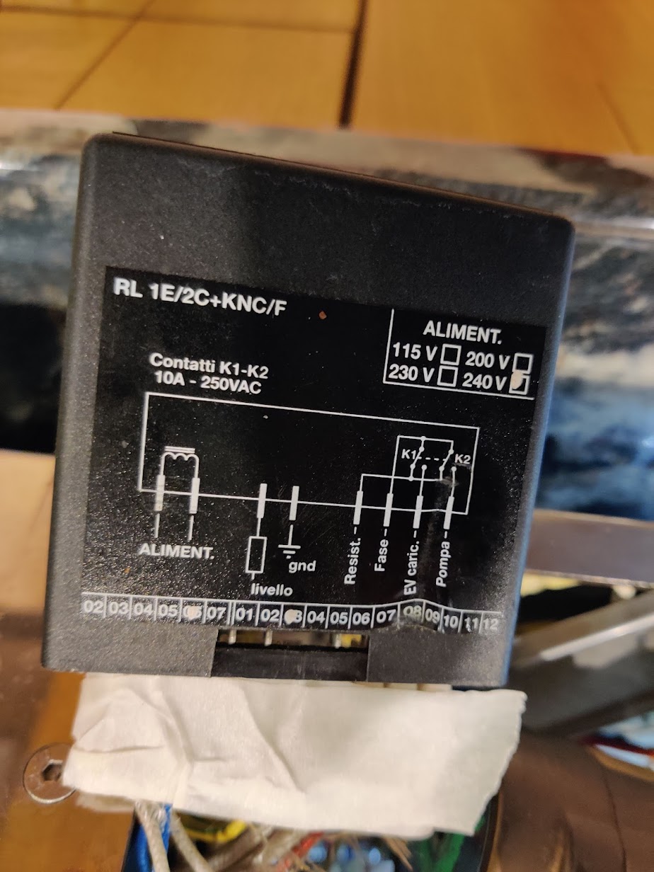
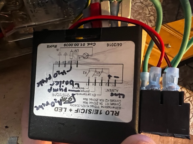
If you search for the brewtus Control Board Retrofit you get a great PDF that shows you the wire config for a RL0 1E/SIC/F + LED or 01.00.0039 Which pretty much matches the old RL 1E/2C+KNC/F with the bonus of two internal relays instead of 1.


I can not find that newer Giemme unit in the UK. My old one I've repaired twice, new transformer and new relay as they do burn out with all the autofilling. My repairs were back when my soldering was, barely ok and a bit hand fisted so I thought time to replace with new.
I took a punt and bought the 01.03.0036 and hooked it up. Bang! oops did something wrong. After much web searching turns out L doesn't mean live it means light, so I had hooked up live and neutral to a closed cirquit, the the reservior low level light which is on one of 3 relays and normally closed. I burnt out the trace!
Fortunately this trace is not needed as I don't use a reservoir, I could fix it but.....
Once I nailed the pinout all is good and it's in and tested. You have to ground out the reservoir sensor or it thinks it's empty and won't heat the steam boiler. I thought I had smoked £85 quid but in the end I'm all good. The contacts on the relay did burn. I pulled it appart to make sure it's not fused and in the process broke both wires off the coil but managed to re-solder them and the relay is working fine. I may replace it one day.
Thought I'd share for anyone wanting to replace the old control unit. This one has 3 internal relays so effectively an upgrade and should be longer lasting. Happy to write up a pinout if there's any demand.


Mike.
R
Jan 5, 2023, 9:39:09 PM1/5/23
to Brewtus
Hi Mike,
I would really appreciate if you would show the pinout you figured out. I have an old Brewtus with a Giemme RL 1E/2C+KNC/F and although still working seeing how you wired up the 01.03.0036 would be very helpful.
Thanks,
Blair
Jason Scott
Mar 16, 2023, 11:40:41 AM3/16/23
to Brewtus
I just successfully bypassed the internal relay on my 2016 board 1.00.0039, (aka the RL0 1E/SIC/F + LED) and in the process I figured out what all the wires were for. But there are some important variables at play:
1. Are you 240v or 120v? (I'm 120v)
1. Are you 240v or 120v? (I'm 120v)
2. Are you plumbed, or do you have a reservoir? (I'm plumbed... reservoir is more complex.)
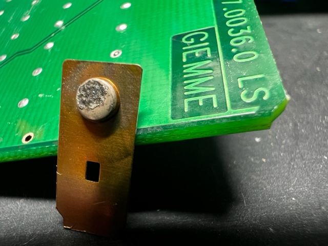
There are many things that are different about the 2 boards posted by the O.P. (it's a 3-relay board that controls more than just boiler elements). In my case, I ONLY needed to control the boiler elements. I upgraded my steam boiler to a 2000w unit, and had to bypass the onboard relay since it's not rated for that much current (and quickly burned out). :) Here's what the contactor looked like after just one attempt at using the upgraded steam boiler:

Terminology that is consistent across all control boards:
1. Aliment - this is your electrical "feed" from the power cord. It literally powers the control board. On 120v units, there is a hot and neutral.
2. EV caricamento (water solenoid valve) and pompa (pump) always activate in tandem. That is, when your pump turns on, you always want the water solenoid valve to open. Thus, these are 2 different wires, but they're always triggered at the same time.
3. LIV (or livello) is a level sensor probe, and if there's only one, it's assumed that it's your steam level sensor. I only have one, but if you have a reservoir, you might have 2. The S. Serb is your reservoir probe.
4. Resistenza is your boiler power wire. It is activated ONLY when your boilers are full. That is, there will only be current on this wire when the water sensor probes are making connection to a ground.
There are many things that are different about the 2 boards posted by the O.P. (it's a 3-relay board that controls more than just boiler elements). In my case, I ONLY needed to control the boiler elements. I upgraded my steam boiler to a 2000w unit, and had to bypass the onboard relay since it's not rated for that much current (and quickly burned out). :) Here's what the contactor looked like after just one attempt at using the upgraded steam boiler:
Terminology that is consistent across all control boards:
1. Aliment - this is your electrical "feed" from the power cord. It literally powers the control board. On 120v units, there is a hot and neutral.
2. EV caricamento (water solenoid valve) and pompa (pump) always activate in tandem. That is, when your pump turns on, you always want the water solenoid valve to open. Thus, these are 2 different wires, but they're always triggered at the same time.
3. LIV (or livello) is a level sensor probe, and if there's only one, it's assumed that it's your steam level sensor. I only have one, but if you have a reservoir, you might have 2. The S. Serb is your reservoir probe.
4. Resistenza is your boiler power wire. It is activated ONLY when your boilers are full. That is, there will only be current on this wire when the water sensor probes are making connection to a ground.
So knowing the terminology above, you can LARGELY figure out what your board is doing (especially if you can follow the simple block diagram on the label). However, some of the differences then come into play and make things more complicated. The contactor/relay designations such as K1, K2, and K3 mean different things on different boards. For my board, K1 is the pump/solenoid relay. For the board on the left in the O.P., the K1 is the boiler relay, and on the board on the right, K1 is the relay for the reservoir LED indicator!
It's worth pointing out that there is only ONE wire (the Resistenza wire) for BOTH boiler elements. This one wire first goes to the pressurestat, and the pstat will determine if that voltage is fed to the boiler element or the brew boiler. If your steam pressure is high enough, it will then send current to the PID unit, which will then determine if/when to send power to the brew boiler.
The board on the left (the
RL 1E/2C+KNC/F) has this odd "Fase" wire, and it appears to me that this is one phase of the electrical supply that then powers the pump or boiler. This appears to be an older design, and I can only speculate that it has 120v on it (but you'd need to hook a multi-meter up to it to be certain).
The bottom line is that these boards are all slightly different, but they operate on the same general principles... they STOP power from being delivered to the boilers while any tank is not full (this keeps your boiler elements from burning up). They then turn ON boiler power when when your tank(s) are full. If you're plumbed, then board choice is simpler (because even a reservoir board can be made to work on plumbed unit, but the opposite is not true).
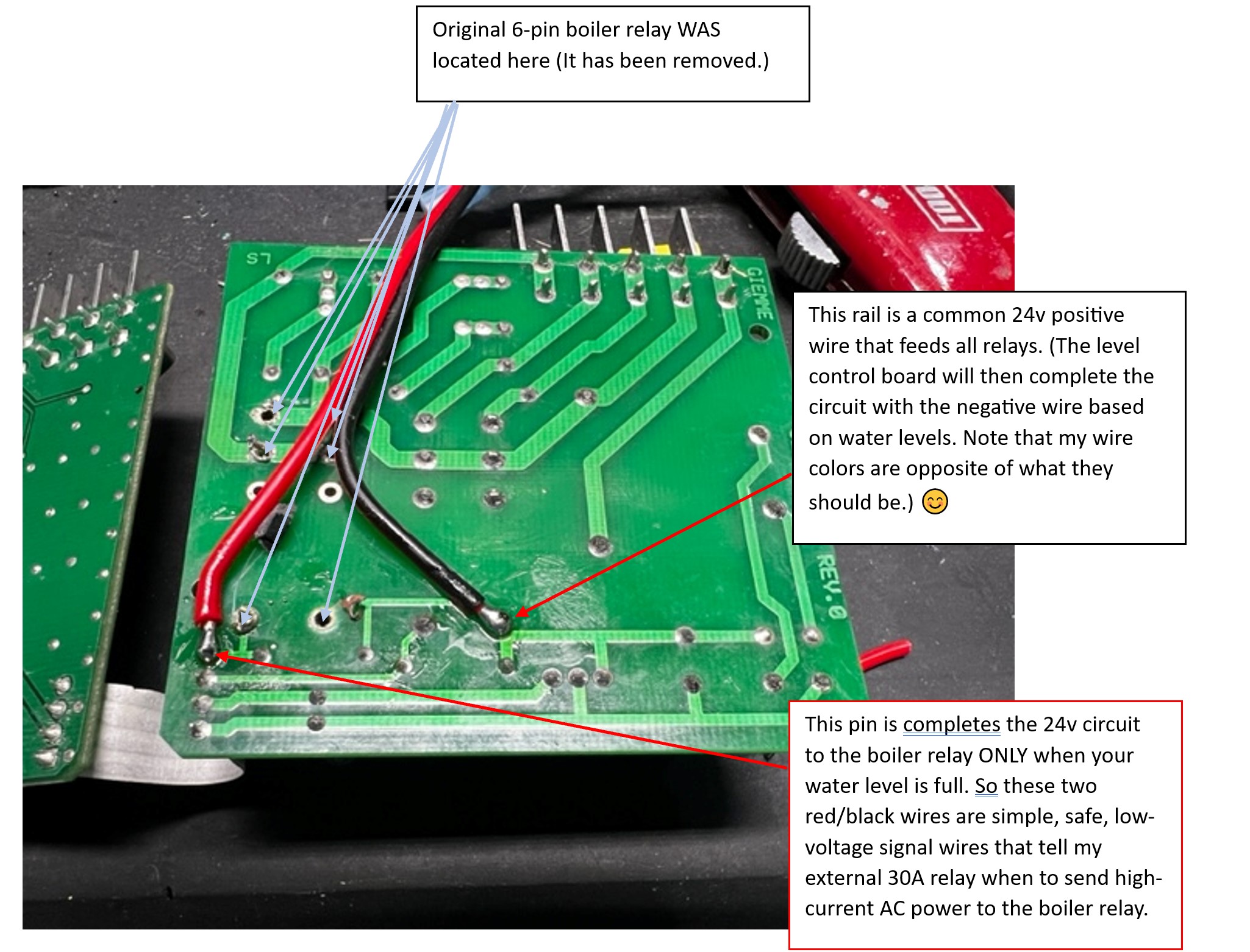
For reference, here's what I ended up with (that's a 30A EXTERNAL relay on the side of the unit now... much beefier and able to handle the 2kw steam boiler):

For reference, here's what I ended up with (that's a 30A EXTERNAL relay on the side of the unit now... much beefier and able to handle the 2kw steam boiler):
The red/black wires above are the 24v DC "trigger" wires for the relay (they tell the relay when to send power to the boilers). THAT 24v signal is sent by the level control board:


I don't know of any of this helps or just further confuses the issue, but the bottom line is that there's a way to make these things do what we need with some simple relays and soldering skills!
Reply all
Reply to author
Forward
0 new messages
