Issues with Xenocs 2.0 Scattering Data in EDF and .nxs Formats
160 views
Skip to first unread message

何承鑫
Sep 13, 2023, 12:37:14 AM9/13/23
to BioXTAS RAW
Dear Administrator,
I am writing to seek assistance with a technical issue I've encountered while working with Xenocs 2.0 for scattering data acquisition in EDF format. Unfortunately, I have been facing difficulties when attempting to display the acquired images in RAW format, as it seems that the pixel coordinates are not rendering correctly. Despite my efforts to adjust the advanced options related to Xenocs, the problem persists.
Moreover, I have also been encountering compatibility issues when trying to open the .nxs files generated after performing buffer subtraction using Foxtort. The error messages I receive vary depending on the advanced settings I use. For instance, with default settings, I encounter the following error message:
"The selected file: cpc.nxs
could not be recognized as a Pilatus image format. This can be caused by failing to load the correct configuration file.
You can change the image format under Advanced Options in the Options menu."
Despite attempting to modify the image format through the Options menu, I have been unable to resolve this issue.
Thank you for your attention to this matter, and I look forward to your prompt response.
Sincerely,
Chengxin

Jesse Hopkins
Sep 13, 2023, 10:14:02 AM9/13/23
to bioxt...@googlegroups.com
Hi Chengxin,
Let me start with your second question. I'm assuming a .nxs (.nx5?) file you're referring to is a nexus file. If that's the case, RAW doesn't support that file format. You'll need to save your processed data in another format. A format that provides the profile as a three column text file (typically called .dat files, but sometimes they have other names) would be best. I'm not familiar with the software you're using to create the buffer subtracted profile so I can't be of much help on how to do that.
For your first question I'm going to need more details. Please provide:
- What version of RAW you're using
- What OS you're using
- How you installed (e.g. prebuilt version like a .exe or .app or running from source)
Additionally, please provide more details when you say it's not rendering correctly. Does it not load the file at all? Does it load the file but not show the image you expect? Does it show the image you expect but not in the correct orientation? Etc. Screenshots would be very useful here, both of what you expect to see and what you're actually seeing.
Finally, I should say that the Xenocs specific options may not apply to your data. I don't have any knowledge of the Xenocs side of things, but I do know that those were written for data from the Xenocs BioXolver instrument. It may be that your instrument (a Xeuss maybe?) doesn't produce data that is compatible with those options.
All the best.
- Jesse
----
Jesse Hopkins, PhD
Deputy Director
BioCAT, Sector 18
Advanced Photon Source
--
You received this message because you are subscribed to the Google Groups "BioXTAS RAW" group.
To unsubscribe from this group and stop receiving emails from it, send an email to bioxtas_raw...@googlegroups.com.
To view this discussion on the web visit https://groups.google.com/d/msgid/bioxtas_raw/29995251-09ea-4132-9297-2a2cba262b63n%40googlegroups.com.
何承鑫
Oct 3, 2023, 5:27:49 AM10/3/23
to BioXTAS RAW
Hi Jesse,
I want to extend my apologies for the delayed response; my Gmail account mistakenly flagged your email as spam, causing the delay in my reply.
I've been encountering an issue with RAW version 2.2.1 on my MacOS 13.6. Even after upgrading from MacOS 13.6 to 14.0, the problem persists. I believe I'm using a pre-built version of RAW.
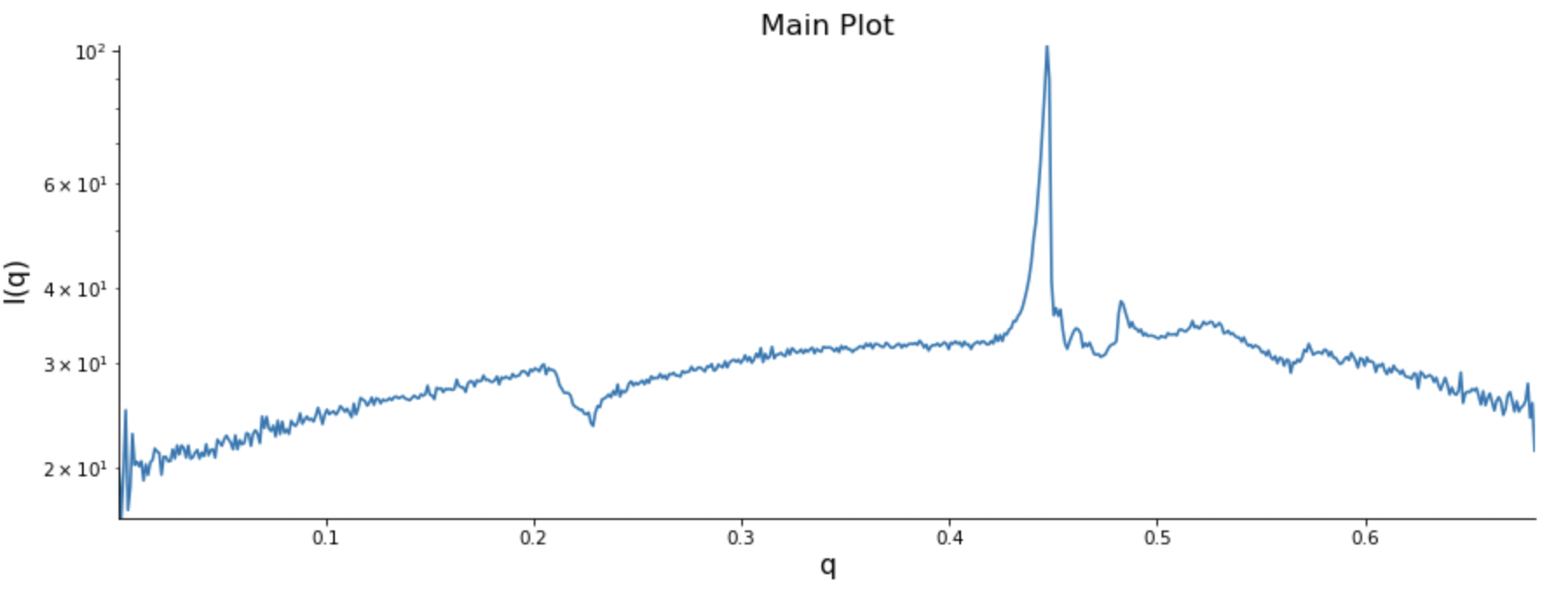
The problem I'm experiencing is related to the x-y direction when plotting the intensity (I) against q-values (A^(-1)). Although RAW can load the file, I suspect that it's incorrectly interpreting the x-y direction, resulting in inaccurate plots.
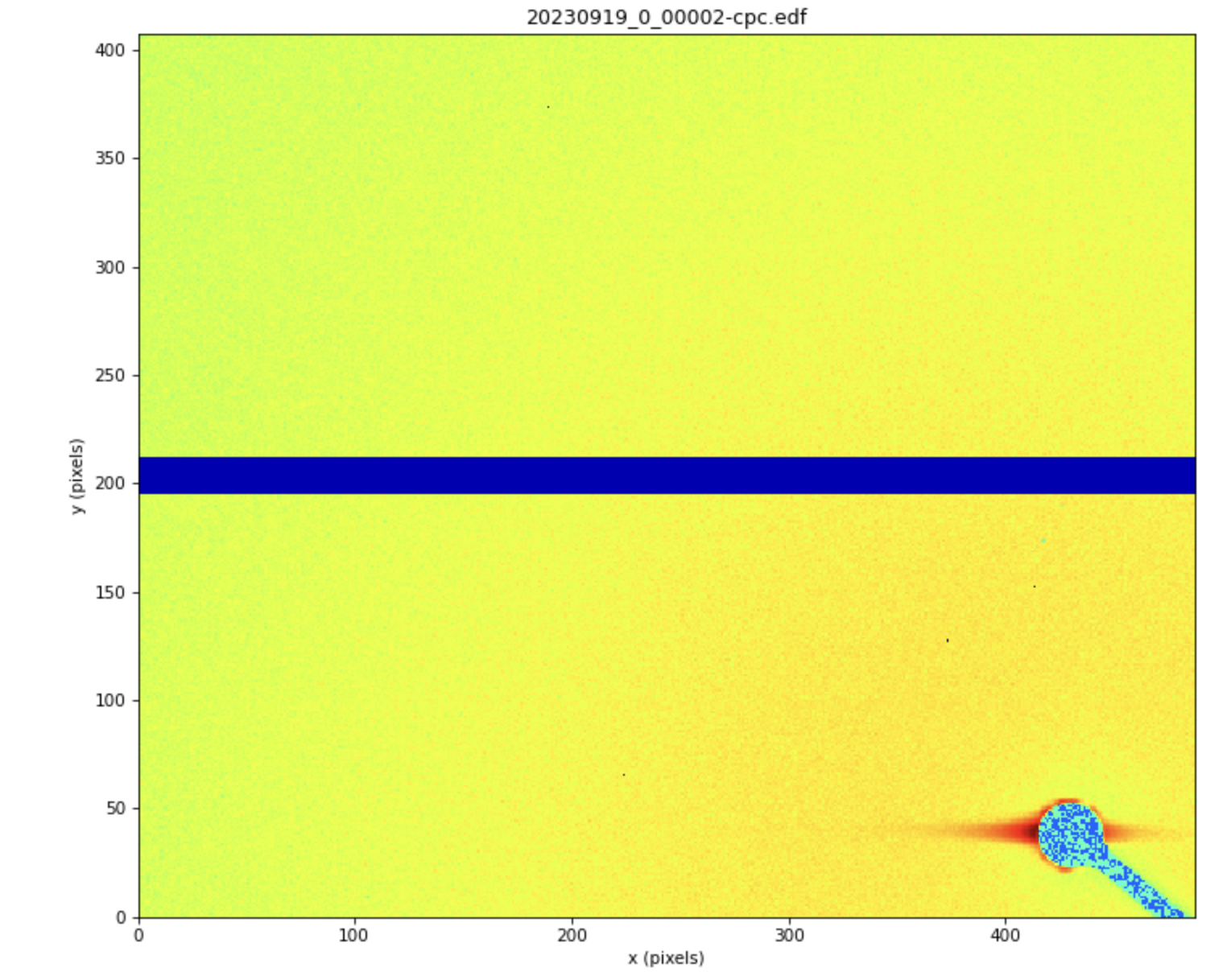
To provide more context, I've attached three screenshots:
-Screenshot 1 and 2: Shows the image and I-q plot in RAW.
-Screenshot 3: Shows the same file in Foxtrot for comparison.
From these screenshots, it seems evident that RAW is interpreting the x-y direction incorrectly, leading to the issue I'm facing.
I appreciate your assistance in resolving this matter.
Thank you for your understanding and support.
Best regards,
Chengxin

I want to extend my apologies for the delayed response; my Gmail account mistakenly flagged your email as spam, causing the delay in my reply.
I've been encountering an issue with RAW version 2.2.1 on my MacOS 13.6. Even after upgrading from MacOS 13.6 to 14.0, the problem persists. I believe I'm using a pre-built version of RAW.
The problem I'm experiencing is related to the x-y direction when plotting the intensity (I) against q-values (A^(-1)). Although RAW can load the file, I suspect that it's incorrectly interpreting the x-y direction, resulting in inaccurate plots.
To provide more context, I've attached three screenshots:
-Screenshot 1 and 2: Shows the image and I-q plot in RAW.
-Screenshot 3: Shows the same file in Foxtrot for comparison.
From these screenshots, it seems evident that RAW is interpreting the x-y direction incorrectly, leading to the issue I'm facing.
I appreciate your assistance in resolving this matter.
Thank you for your understanding and support.
Best regards,
Chengxin
Jesse Hopkins
Oct 3, 2023, 10:50:01 AM10/3/23
to bioxt...@googlegroups.com
Hi Chengxin,
So there's likely two things going on here. First, if you want the image to be flipped to match that in the bottom screenshot, in the Advanced Options->General settings section, check (or uncheck) the "Flip detector image left-right (non-Xenocs)" box. My guess is that despite having a Xenocs instrument, since you don't have a BioXolver you aren't using the Xenocs specific code in RAW, so this option will let you control the image display. I'd also recommend not selecting any of the Xenocs specific options for the same reason. See attached screenshot.
The second thing is that in order to reduce a 2D image to a 1D scattering profile you need to provide various calibration settings, such as the sample to detector distance, the energy you're working at, and where the beam is on the detector. You also need to make a mask for the image. In RAW we store these parameters and mask in a configuration (cfg) file. I don't know how Foxtrot works, but either you or someone else must have calibrated these parameters in it at some point in order to do the reduction. You can do the same thing in RAW if you want, but you'll need access to instrument specific calibration data. You can find an example that uses tutorial data here:
But note that you'll need to provide data specific to your instrument in order to make a working configuration file for your system.
I'm happy to answer questions about the calibration process if that's something you want to do with RAW. Otherwise, you could use Foxtrot to reduce the images, save those reduced 1D profiles, and then load them into RAW for further processing.
All the best.
- Jesse
----
Jesse Hopkins, PhD
Deputy Director
BioCAT, Sector 18
Advanced Photon Source
To view this discussion on the web visit https://groups.google.com/d/msgid/bioxtas_raw/e58fbafa-7ff3-4af5-962c-4579445dd805n%40googlegroups.com.
何承鑫
Oct 4, 2023, 1:15:02 AM10/4/23
to bioxt...@googlegroups.com
Hi Jesse,
I follow your guide, now the image can shows correct.
I am reaching out to seek clarification regarding the need to establish a standard configuration for my data analysis project, which involves working with EDF files. I've observed that RAW can automatically extract certain configurations, such as sample distance information, from the image header. Given this capability, I am unsure whether it is still necessary to create a new standard configuration. I am aware that manual mask creation is required, but I am seeking clarity on this specific aspect.
Additionally, are water, glassy carbon calibration, and absolute molecular weight set necessary for analysis? Our SAXS has done glassy carbon calibration. Generaly saxs software only need create a mask and use some information about instrument (e.g., the sample distance), I think. Is my understanding correct?
Your guidance on these matters would be greatly appreciated. Thank you for your assistance.
Sincerely,
Chengxin
Jesse Hopkins <jesse.b...@gmail.com> 于2023年10月3日周二 22:50写道:
To view this discussion on the web visit https://groups.google.com/d/msgid/bioxtas_raw/CAGRN2W3o3%2BA0Ub25bATeKn9cRfE4wg4dZcjZW_kczsaZgdURPQ%40mail.gmail.com.
Jesse Hopkins
Oct 4, 2023, 12:55:32 PM10/4/23
to bioxt...@googlegroups.com
Hi Chengxin,
RAW can extract information from headers, either from the image or an accompanying text file, but in that case you generally still have to tell it what header value corresponds to what internal value (for example, in the header you might have something called "distance" and you need to tell RAW that corresponds to "Sample Detector Distance" . Providing that information is something that would go in a configuration file. In this part of the tutorial, if you go through the first three steps, using your data, you can see what information RAW is reading out of the header file:
Without seeing your data I really can't provide more help, but if you send me an image I can probably provide more specific instructions.
As far as absolute scale calibration goes, no you don't have to do it. It is recommended, but it is not always done. That's up to you, and whether you've measured the appropriate calibration standard, either water or glassy carbon. However, if you've already measured glassy carbon, I don't see why you wouldn't use that to set the absolute scale.
All the best.
- Jesse
----
Jesse Hopkins, PhD
Deputy Director
BioCAT, Sector 18
Advanced Photon Source
To view this discussion on the web visit https://groups.google.com/d/msgid/bioxtas_raw/CAJ857FJ0eEHjfweAaL5vn0A2nF5Rqu6W3X5rRso4yK7KuyiZ3w%40mail.gmail.com.
何承鑫
Oct 5, 2023, 11:09:33 PM10/5/23
to bioxt...@googlegroups.com
Hi Jesse,
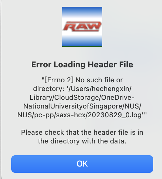
I follow the guide but it seems that the head file format is incorrect. After I set it to BioCAT, APS, I even can not load my edf file. Attached my file:
Thanks for your kind help.
Chengxin
Jesse Hopkins <jesse.b...@gmail.com> 于2023年10月5日周四 00:55写道:
To view this discussion on the web visit https://groups.google.com/d/msgid/bioxtas_raw/CAGRN2W0OWCs94%3DXqTkCu9zWtJaw81r3BDY9kv8soh6YdxRofCA%40mail.gmail.com.
Jesse Hopkins
Oct 6, 2023, 11:19:28 AM10/6/23
to bioxt...@googlegroups.com
Hi Chengxin,
So following the exact steps of the configuration tutorial will only work for the tutorial data. A configuration has to be specific to your data and your instrument. In the case that you mention, selecting the "BioCAT, APS" header means that RAW expects a header in the format used at the BioCAT beamline at the APS, which isn't what you have.
There will be a number of places where you will need to use the correct values for your data rather than values in the tutorial. Off the top of my head:
- Image format
- Header file format
- Detector orientation
- Detector type
- Masking should be done off of your own images
- Centering and calibration should be done off of your own images
- Setting the normalization counter
- Setting absolute scaling
- Start point/skip end points values
- Metadata
- Setting a MW standard
My recommendation is that you first create a configuration file with the tutorial data, so you understand how the process works, then you go back and start fresh and create a configuration file with the particular settings necessary for your data.
In the particular case of the Header file format, I would use "None". The header file is a separate text file that is read in with the image and contains relevant values, such as normalization counters. If you need to read in such a file, you'd probably have to write a specific reader for it (which I could help with), or change the file format to match one of the existing defined formats.
Setting the image file format to none I am able to read in the image header (see attached screenshot). It does seem to contain at least some of the values that you need for reduction, including what I assume is the sample to detector distance ("SampleDistance") and the wavelength ("Wavelength").
Here's how you would use those:
1) In the image/header format section check the "Use image-header/header file for calibration and reduction parameters" box.
2) Select the value of interest in the list by clicking on it.
3) At the bottom of the options window in the "Binding" drop down menu select the appropriate value
4) If necessary, apply a modifier to convert units and click "Add". For example, RAW expects the sample to detector distance to be in mm, and in the header it appears to be m, so I would use a modifier of 1000. You have to write an expression that includes the modifier and the original header value, so in this case it would be "SampleDistance*1000"
5) If you've successfully added the binding and any modifier it will show up in the header value list.
I've attached a series of screenshots showing these steps.
Finally, it turned out to not be very hard to make a working configuration from your data, so I did, and it is attached. You might want to refine the mask. Note that with this configuration the image isn't displayed the same in RAW as in foxtrot. This is due to a difference in where the coordinate systems 0s are defined. RAW defines the 0s in the bottom left corner of the image display, whereas the screenshot you sent from Foxtrot shows the 0s in the upper left. In order to use the beam center positions defined in the image header you have to accept this change in orientation of the coordinates. If you instead want to recalibrate using the silver behenate image you sent, you can orient the image whatever way you want and then redo the beam center calibration. In that case you will need to remove the binding for the beam center position in the header list.
I hope all of that helps.
All the best.
- Jesse
----
Jesse Hopkins, PhD
Deputy Director
BioCAT, Sector 18
Advanced Photon Source
To view this discussion on the web visit https://groups.google.com/d/msgid/bioxtas_raw/CAJ857FKnVUnbX3Jao4xLDs%3DbS3KH%2BDMBVO1EP4ivx9EQD9nrjg%40mail.gmail.com.
Jesse Hopkins
Oct 6, 2023, 11:22:12 AM10/6/23
to bioxt...@googlegroups.com
Chengxin,
One other thing about the configuration file I sent: it doesn't include any normalization, because I wasn't sure what value to use for that (maybe count time?). So you'll need to add in the normalization yourself if you use that test.cfg file I sent in my previous email.
All the best.
- Jesse
----
Jesse Hopkins, PhD
Deputy Director
BioCAT, Sector 18
Advanced Photon Source
何承鑫
Oct 6, 2023, 11:36:19 AM10/6/23
to bioxt...@googlegroups.com
Hi Jesse,
Thanks for your generous helps. I will try to understand your guide.
Thank you again.
Regards 😁
Chengxin
Jesse Hopkins <jesse.b...@gmail.com> 于 2023年10月6日周五 23:22写道:
To view this discussion on the web visit https://groups.google.com/d/msgid/bioxtas_raw/CAGRN2W2yujO3o9a4Ui0w4%3DJMHj7Jko9mhjjWE3F55aKdb9%2BfKw%40mail.gmail.com.
Reply all
Reply to author
Forward
0 new messages