Skip to first unread message

woody stanford
Jan 30, 2017, 8:19:30 PM1/30/17
to BeagleBoard
I posted the remote control for this in Software, but I put a bunch of hardware in it so I thought I'd post it here.
woody stanford
Jan 30, 2017, 8:32:20 PM1/30/17
to BeagleBoard
Still trying to find my blueprints for it (I think its on my Ubuntu box, but my monitor is fried on it, grrr, and I'm sure its not accessable on FTP, I'm on my Windows 10 workstation now), but here is an interesting example of MOSFET motor speed control via GPIO or PWM.
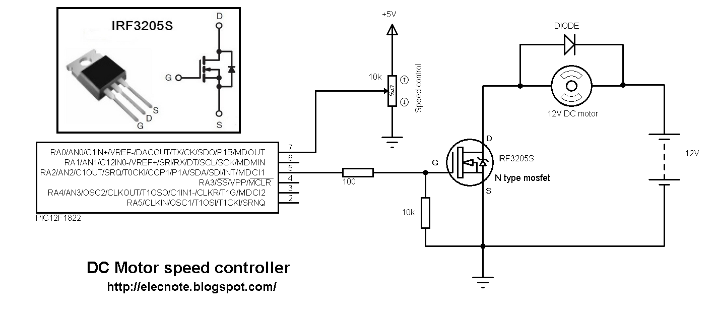
The top center part of it is kind of dumb in that I think their point is to use a pot read by an ADC to do the speed control. However I would do it via UART or software instead. However the rest of the circuit is a great example of real motor speed control using an inexpensive MOSFET driven by MCU or BBB PWM.
woody stanford
Feb 2, 2017, 1:04:09 AM2/2/17
to BeagleBoard
OK, just got my BBBW wireless acquiring well over about 200 feet (indoors) and about 400 feet (outdoors) so I have enough of a wireless tether to actually fly my drone. Very impressed with this little unit (the BBBW); I was a little concerned over the little antenna but they seem to work nice.
Next step is to integrate my MCU6050 inertial unit to it via P8/9 I2C (only interface on it). Its a 6DOF that I got from Hong Kong for about $5 free shipping, its on a break out board and even has an "attitude engine" on it. Why this is important is that back in the day, iMEMs stuff like piezo gyros and accelerometers were only 1DOF voltage-out, but this one not only has the ADC's onboard, they are controlled with their own MCU that calculates to x,y,z,vx,vy,vz,ax,ay,az,tx,ty,tz and I think even rate) and allows the host (in this case the directly connected BBBW) to just receive the actual data we need.
If you want to experiment with the MCU6050 it is 3.3v so compatible with the BBBW right out of the box, uses I2C and only $5 total on ebay (just search on the part number) comes mounted on breakout board with 0.1 header (like SIP) that you just solder on. I'll post up here as I have successes with interfacing it. I can also provide download locations for my tablet-based drone remote (windows installer) as well as code example on the NEO6M, PIC and MCU integration.
I wanted to go nuts with external MCU's but now I'm thinking that I'll have a 3.3V domain and a 5V (TTL) domain on my power section so I'll get my PIC (5V) doing the PWM for the motor speed control. It will have 8 motors counterrotating per pod (I think I might have a sweet way of controlling yaw through coordinated power throttling). So I'll be able to finally use my bootleg K150.
I'm thinking maybe voltage divider (resistive....I'll put up some sweet discrete networks here so we have some reference designs to bridge cheaply and small-ly between the two voltage domains and others) to translate signals from TTL (5V) down to 3.3v (we did this with RS232 with the PIC for years and years now), and an led-heatshrinktube-phototransistor from 3.3v up to TTL (5V) forming a tiny single line/single direction optoisolator.
Actually scratch that, here is a $0.18 jobbie that does exactly the same thing. Looks like optocoupler will do it if I can keep the discretes count low.
On Monday, January 30, 2017 at 6:19:30 PM UTC-7, woody stanford wrote:
woody stanford
Feb 2, 2017, 1:16:33 AM2/2/17
to BeagleBoard
OK, let me explain what I'm doing here. A lot of you realize that what I'm building here is more of a tiny UAV than a toy drone, but I want to have enough processing power on-board that I can do whatever I want.
How its different is my design philosophy in that what I'm trying to do here is shift the majority of my work to a software domain from a hardware/power one. I'm just going to breadboard and build the drone, but all of my flight control will be done with TCP/IP stack with the processor running a service daemon that provides the guidance I'm looking for.
It will be based on a force-moment-mass model based on empirical tests (and weighting the darn thing) that will formally implement a drone control that is smooth, scientific and possibly autonomous that is 100% done in software (based on SENSOR and ACTUATOR section in the physical design). In other words, it will be sweet once finished, capable of long-range semi-assisted flight. I'm thinking of integrating 4/5G data (via USB model model) but only pushing across limited numeric data (caching its video) to keep my usage within plan, but I hope to be able to send a command that will return (via FTP over 4/5G) a nice compressed JPEG still whenever I want to see a location.
I'll just pull the saved video off via manual FTP via wifi once it comes back into range, or just popping the SDCard on the cam itself (which might made more sense, though less techy).
Getting close to that time I need to start ordering stuff from mouser but I need to get a complete BOM together for the physical stuff.
I'll keep you guys in the loop on this one (as a lot of the issues I'm solving are directly related to your projects like voltage conversion) but I want to warn people that the final result may not be open-source as I might choose to release it as a boilerplate commercial version. However I can still make notes here to help in your own projects, and you can shadow my development and processes to develop your own (possibly open source).
On Monday, January 30, 2017 at 6:19:30 PM UTC-7, woody stanford wrote:

Graham
Feb 2, 2017, 10:55:42 AM2/2/17
to BeagleBoard
Woody:
If you are translating between 3.3 and 5 Volts I2C domains,
I recommend you use the PCA9306, Available from TI or NXP.
Adafruit has breakout boards, if you want to experiment.
--- Graham
==

Jason Kridner
Feb 2, 2017, 11:46:10 AM2/2/17
to BeagleBoard
This is pretty great. Will you add to hackster.io and/or Hackaday.io?
--
For more options, visit http://beagleboard.org/discuss
---
You received this message because you are subscribed to the Google Groups "BeagleBoard" group.
To unsubscribe from this group and stop receiving emails from it, send an email to beagleboard...@googlegroups.com.
To view this discussion on the web visit https://groups.google.com/d/msgid/beagleboard/bd29a8a3-6401-4bf3-b8be-5058a78bef54%40googlegroups.com.
For more options, visit https://groups.google.com/d/optout.
woody stanford
Feb 2, 2017, 8:20:39 PM2/2/17
to BeagleBoard
OK, set up an account there. I'll copy this over later. Good to see you Graham and Jason again :D
woody stanford
Feb 4, 2017, 1:25:02 AM2/4/17
to BeagleBoard
Ok want to brag. And just remember envy is ugly.
I was expecting to pay $14 for some angel motors out of hong kong, but I found some nice $5 ones with the same specs. Read them and weep:
They are even gold colored. Hopefully they work well, but all of the stuff I've gotten so far out of Hong Kong is nice. Even comes in the nice little anti-stat bags. But I have a confession to make, that I'm liking this whole spree I'm on...I have some lead/tin solder coming in. I've looked at the natural consequences and realizing that my prototyping (no matter how prolific) wouldn't affect the lead content of things one iota, so I'll save myself the aggravation of silver (oh god, the aggravation of working with that metal, anyways).
I even have an absolutely barbaric 30W iron from Chicago Electric (I think it even sings opera)...a real board-destroyer in any but expert hands. I need to feed it right.
On Monday, January 30, 2017 at 6:19:30 PM UTC-7, woody stanford wrote:
woody stanford
Feb 4, 2017, 1:44:05 AM2/4/17
to BeagleBoard
To continue the brag, I had a small sum set aside to do some 3D printing...however I have seen the real quotation numbers on it. Noy much like the next inkjet like how they say.
So I was out a connection system for rod, but got a little intuition and got a big bag (a literal big bag) of 1/2" dowel end caps. But what makes them special is this little protrusion with a 1/8" hole through them that is the key to success here I think. I've looked at it geometrically and I think I have a winner.
I'm thinking of doing a trick I used to do back in the day where I mix up some chips of ABS plastic (of of an old pipe or something) and mix in acetone and mix until its a nice thick paste. Then I solvent weld the hell out of whatever plastic I'm using (crossing my fingers these little jobbies I have secured for my own use are of a compatible plastic) but I am SURE that it will lead to the intended effect and a practical drone prototype.
But I have been looking at the forces and loads and realize that I might have to put a kind of mast right in the center of the base board that doesn't have me pleased (though it does it make it some what look like a ship, I understand there are some people into that). However I wouldn't say its typically my aesthetic.
If it works half as perfectly as I'm anticipating I will post more of this technique here because it seems the WAY to realistically produce prototyping geodesics because of the flexible approach. We will see.
On Monday, January 30, 2017 at 6:19:30 PM UTC-7, woody stanford wrote:
woody stanford
Feb 4, 2017, 2:30:24 AM2/4/17
to BeagleBoard
Let us look at these motors again. A lot of you are doing (well, thinking of) drone projects so let's talk a little about my little Beagle and thick-conductored "hot" motors, How we get them making sweet electric love with each other.
Ok what you do is you feed off of one of your PWM or GPIO lines of your favorite beagle. Both have their downsides. Hardware PWM is lacking a certain jeun-se-quoi, its just a little too digital (those that have worked with it before know what I'm talking about). However software-based PWM (how motor speed control is done) via GPIO I would surprised is good on a multitasking OS environment like UN*X. Maybe with interrupts...idk.
Of course my solution is elegant. I went out and saw how fast I could get a UART to go, apparently 128K baud...this is acceptable. What you do is you use a slave PIC16Fx (the F means flash btw) and I run a 5V zone next to my Beagle's 3.3V one. The beauty of this approach is I've decided that I'm going to drive these motors DIRECTLY off of my Nickle-Metal Hydrides, no caps just spread my error over an inductive domain than a capacitive one (***knowing look***).
Can see my new buddy, Graham, wondering if he should whip out the old complex numbers on this assertion.
Can you do ESC direct from GPIO or PWM off of your Beagle? I suppose. And you might try it. Just pull directly off of a PWM line and feed it to the SSR at the front-end of what I'm talking about. I am not adverse to it other than the whole getting UN*X to do it. Maybe one of Lidia's sitaras (I mock) and that PRU to do it. In fact, I would suspect, that that's the whole point of the PRU issue.
So you get your PIC to accept on its hardware UART a byte of which motor speed you want to control (I need to control 8). Then I send it an int (2 bytes) with how long on it is, and then an int of how long off it is. And just implement it in a software loop completely bypassing the PIC's hardware PWM as well. It just drives 8 GPIO's leading to nice multi-stage ESC. We feed this nice PWM signal to the SSR's which drive directly to MOSFET, and accept for the blowback rectifier, we are going to run this bare-metal as they put it (semiconduction aside).
"You can do it this way?" Its me, dear, I wouldn't steer you wrong.
OK so let's look at the power train. We have 1.2V NmH's strung in series to give us about seven volts of beefy power (and we have the same number of cells as our motors) so I'm just going to say 2.5 Amp hours of juice (the rating of one cell). We use our stock BBBW to communicate with the PIC (that's actually doing the speed control) via probably optoisolator-step-up, to custom programmed 5V PIC and then we just pull of its GPIO to cheap SSR direct to cheap MOSFET direct to beefy motor. I so know this will work. Somewhat improper I'll admit, however life isn't perfect. I can just tell this has the characteristics I likey. :D
I'll put up a schematic, maybe even a PCB, of what I'm talking about here (tested) so you can use these little drone motors easily.
Theory: you'll find these ones come in 2.2KV and 1.0 KV. I'm hoping my advisors have instructed me correctly that with the battery type I'm using, connection, propellers bought that it will transfer my battery power to nice upward force linearly and predictably. I got a grip of 1.0KV ones. the KV rating pertains to the RPM per volt. So a lower value would mean less RPM's per volt, a higher higher RPM's. From an engineering perspective what you want to do is look at the whole power subsystem seeing that you get a tight linkage between your power source and actual FORCE generated by the propellers. You can't just say the 2.2KV ones are "better" or "more powerful" or you might end up with a system that's electrically perfect but just doesn't transfer power right.
Anyways...in conclusion...(UART to external MCU) to SSR to MOSFET direct to motor. Or PRU to SSR in previous description.
On Monday, January 30, 2017 at 6:19:30 PM UTC-7, woody stanford wrote:
woody stanford
Feb 4, 2017, 5:54:45 PM2/4/17
to BeagleBoard
Ok, Here is the quick-and-dirty version:

On Monday, January 30, 2017 at 6:19:30 PM UTC-7, woody stanford wrote:
woody stanford
Feb 4, 2017, 6:17:55 PM2/4/17
to BeagleBoard
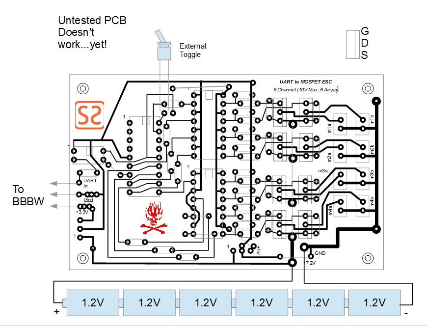
OK, values, sorry for not putting them on there. The resistor network on the far left side of the schematic is a standard voltage-divider for doing a low-cost....ok.....I JUST MESSED UP (proving my point about getting schematics directly from the internet). There are a LOT of things wrong with this schematic. That;s why you breadboard first before doing anything real.
The voltage-divider is going the wrong way. What you need to do is a step-up optoisolator (or SSR which is just a bidirectional optoisolator on the output stage) to step up the 3.3V to the 5V necessary for that "zone". Hang onto the voltage-divider discretes network through because you might want to pass your PIC's TX back to the BBBW (move the voltage-divider down one pin (from pin 7 to pin 8) on the PIC to its UART TX and feed it to the BBB's UART_RX) to pass any "status" information back (I think its overkill but oh well...you don't need status from your external MCU...traces too short).
OK the resistor values on that discretes network can be found in my voltage-division post. I'm pretty sure about the values, but test, test, test.
OK, your "series" resistors can be obtained by our reference MOSFET design (which has a problem to, I think its blowbacks are backward backward, AND its battery is backward too...maybe). Its value is 100 ohms.
Your "bypass" resistors (between the source and gate on your MOSFETs) is 10K ohms. This is necessary to satisfy the local network requirements for your transistor usage, with it being a low enough resistance that we can trip the FET in switching mode yet high-resistance enough that small enough current that we aren't paying anything for triggering.
I tried to integrate the reference design's pot voltage-divider to ADC so we could have variable speed on test, but the particular PIC I'm using doesn't have ADC, so I just wired a switch that will bring all channels up to 20% PWM. Just flick it (even without the BBB attached) to power up your motors to test. Just use a small toggle switch.
XTAL is 20 Mhz (unless the PIC I'm using is old-style, which I think is 4 Mhz). Try to get an MCU with 20 Mhz though, the faster the better. PWM should really be done at about a few 100 hz at least to iron out the power transfer. You do this in PIC firmware by counting the instruction cycles in your source code x your crystal speed).
On Monday, January 30, 2017 at 6:19:30 PM UTC-7, woody stanford wrote:
woody stanford
Feb 4, 2017, 6:28:42 PM2/4/17
to BeagleBoard
And another concern that came up is you might need resistors on the PIC's GPIO out to the LED's on the optoisolators, like how you always use a certain resistor to a standard LED when using TTL (5VDC).
How do I power each of the zones. Figure it out holistically on current usage by component, but I'm sure you can just use 3.3VDC and 5VDC voltage regulators (the 7405 being typical for 5V) direct off of the 7.2 VDC zone. (You might want to soften out any spikes through with some mid-value caps though just to be on the safe side.)
On Monday, January 30, 2017 at 6:19:30 PM UTC-7, woody stanford wrote:
woody stanford
Feb 4, 2017, 6:45:44 PM2/4/17
to BeagleBoard
What are the currents involved. This pertains to the gauge of wire you need to use for everything.
Typically you are looking at about 6 full amps on EACH of your motors (this is kind of high, but what people said...I'm thinking at 100% PWM duty cycle). So make sure your especially ground return on your native zone is wired with like extention cord. Also remember to discharge each of your NmH cells symmetrically with all the other cells. NmH is sensitive to memory effect (unlike LiPo or Li-ion which is much more forgiving) so try to drain them symmetrically and fully somehow.
Li-ion is something like 3.6 V...remember that your NmH's are only 1.2 so you'll have to use series to get their voltage up. 3 NmH (series connected) = 1 Li-ion cell on voltage. To calc amp-hours just add up the number of cells x their individual Amp-hours.
On Monday, January 30, 2017 at 6:19:30 PM UTC-7, woody stanford wrote:
woody stanford
Feb 5, 2017, 3:02:58 AM2/5/17
to BeagleBoard
OK, here is my best guess. I'll need to breadboard it out to get it working. It basically glues some reference designs (off of the Internet...beware lol) with some approaches that I've used for years together. I have to admit that I'm a little shaky in the MOSFET area, but I know I can get a design like this to work with some fiddling.
I would recommend to someone trying to get this to work to breadboard a SINGLE CHANNEL of it, maybe using the PWM on the BBB PRU to output signal to the optoisolator stage of the circuit. Or if you can find a solid pre-programmed PWM PIC out there (and there are quite a few smaller operators that sell ASIC-type preprogrammed PIC's with some operation or function on them...for example, hobby servo control is a nice starter design to mess with) to drive your isolated power electronics with some kind of off-the-shelf motor.
*** Can you treat a propeller like a resistor? ***
An interesting idea I had was to treat my motor-propeller combination as a true electrical component, looking at it from a power transfer perspective. What I mean by this is there are equations out there that model perfectly a propeller's force and a propeller's effective power transfer to the air it pushes, that I suspect that you can equate the electrical equations involved with the mechanical POWER ones for propellers (and the electromechanical setup of the motors used to drive them). An idea. But it would allow you to fully model a drone's power systems in a way I don't think heretofore done.
OK here we talk about how to power the 3 voltage zones. You'll notice that I've chosen holistically to do it with dumb voltage regulators and this is a product of kinesthetically "knowing" the current draw on each of the zones. The BBB is probably a little more of a power hog than people give it credit for, though I can feel the heat coming off it to be not much, so I'm sure it can be driven off of VR. The PIC the same...very energy efficient so a 7405 will keep my workload low. Also added are some pulldown resistors (on the "optional" network) because I'm afraid my MOSFET's are going to "float" (they call it) and have the BBB to PIC issue worked out (you can float PIC lines because they have built in pulldown resistors).
Again, untested. I don't use this term loosely. There is no guarantee that this circuit will even work at this stage.

On Monday, January 30, 2017 at 6:19:30 PM UTC-7, woody stanford wrote:

John Syne
Feb 5, 2017, 12:25:22 PM2/5/17
to beagl...@googlegroups.com
On Feb 5, 2017, at 12:02 AM, 'woody stanford' via BeagleBoard <beagl...@googlegroups.com> wrote:OK, here is my best guess. I'll need to breadboard it out to get it working. It basically glues some reference designs (off of the Internet...beware lol) with some approaches that I've used for years together. I have to admit that I'm a little shaky in the MOSFET area, but I know I can get a design like this to work with some fiddling.I would recommend to someone trying to get this to work to breadboard a SINGLE CHANNEL of it, maybe using the PWM on the BBB PRU to output signal to the optoisolator stage of the circuit. Or if you can find a solid pre-programmed PWM PIC out there (and there are quite a few smaller operators that sell ASIC-type preprogrammed PIC's with some operation or function on them...for example, hobby servo control is a nice starter design to mess with) to drive your isolated power electronics with some kind of off-the-shelf motor.*** Can you treat a propeller like a resistor? ***An interesting idea I had was to treat my motor-propeller combination as a true electrical component, looking at it from a power transfer perspective. What I mean by this is there are equations out there that model perfectly a propeller's force and a propeller's effective power transfer to the air it pushes, that I suspect that you can equate the electrical equations involved with the mechanical POWER ones for propellers (and the electromechanical setup of the motors used to drive them). An idea. But it would allow you to fully model a drone's power systems in a way I don't think heretofore done.OK here we talk about how to power the 3 voltage zones. You'll notice that I've chosen holistically to do it with dumb voltage regulators and this is a product of kinesthetically "knowing" the current draw on each of the zones. The BBB is probably a little more of a power hog than people give it credit for, though I can feel the heat coming off it to be not much, so I'm sure it can be driven off of VR. The PIC the same...very energy efficient so a 7405 will keep my workload low. Also added are some pulldown resistors (on the "optional" network) because I'm afraid my MOSFET's are going to "float" (they call it) and have the BBB to PIC issue worked out (you can float PIC lines because they have built in pulldown resistors).Again, untested. I don't use this term loosely. There is no guarantee that this circuit will even work at this stage.
Well, it won’t work because the diode of the optocoupler is connected incorrectly.
Regards,
John
On Monday, January 30, 2017 at 6:19:30 PM UTC-7, woody stanford wrote:I posted the remote control for this in Software, but I put a bunch of hardware in it so I thought I'd post it here.
--
For more options, visit http://beagleboard.org/discuss
---
You received this message because you are subscribed to the Google Groups "BeagleBoard" group.
To unsubscribe from this group and stop receiving emails from it, send an email to beagleboard...@googlegroups.com.
To view this discussion on the web visit https://groups.google.com/d/msgid/beagleboard/eea20b90-eda4-474e-8ab6-515f8689cd8f%40googlegroups.com.
woody stanford
Feb 5, 2017, 9:07:37 PM2/5/17
to BeagleBoard
Check it. Doesn't work though. My dyslexia apparently. However this is what it will look like when finished. About 7" x 5". Machine screw it to the basswood or laminate baseboard on the drone and this is the complete BBB controllable power stage.
On Monday, January 30, 2017 at 6:19:30 PM UTC-7, woody stanford wrote:
woody stanford
Feb 5, 2017, 11:30:54 PM2/5/17
to BeagleBoard
Managed to dig up the blue prints for the physical drone. Nice boilerplate design using 0.5 wooden dowel coupled with "geodesic" joins with wire to hold it in tension. I CA the GPS chip antenna near the center, but I need the MCU6050 inertial right at the center of gravity so I might put it on wire and even epoxy it right to the drone's center of gravity. My Emerson cam just mounts on a single hole driller through the baseboard and is its own independent subsystem (though it could be integrated later with the USB on my BBW).
I just got the motors in today....significantly smaller than what I visualized in my head. I'll report on this later. Luckily we have 8 of them.

On Monday, January 30, 2017 at 6:19:30 PM UTC-7, woody stanford wrote:
woody stanford
Feb 6, 2017, 1:05:21 AM2/6/17
to BeagleBoard
OK (laughing my ass off)
I'm joking around on most of this, but it does make you think.
Came up with some super-cool ideas for this:
- Full citywide 4/5G TCP/IP stack communication by 4/5G USB module (with capacity to take and transmit JPEG stills of an area, usually just pushes numeric data to keep it within plan)
- Urban Surveilance and Pasification Unit. (a USPU....just made it up...lol jk) Just mount a police-strength white LED flashlight on the underside of it and turn it on and off via PIC-driven relay and power it directly off your Li-ions.
- Fly you "colors" on the underside of it "militia-style" so they know what "faction" it is.

My choice for what "colors" I would fly on the underside.
- Tired of not having shell access handy when you need it. Just call in a drone and patch in at short-range. However your source code will fly away when you are finished. For serious UN*X guys needing shell access on their terms. Complete with C and python stock.
I'm joking around on most of this, but it does make you think.
On Monday, January 30, 2017 at 6:19:30 PM UTC-7, woody stanford wrote:
woody stanford
Feb 8, 2017, 4:47:46 AM2/8/17
to BeagleBoard
Ok here is what I have so far. I'm almost finished with the geodesic (I still want to "solvent weld" the joints though). Need to swap out the wire with picture-hanging wire and get the basswood "base board" to mount my electronics on. I'm going to do the motor mounts as aluminum plates that I'm going to Drexel fabricate. Looks like I'm going to have to go with the mast approach to get my mentioning right though it will make moving my boards around difficult.

On Monday, January 30, 2017 at 6:19:30 PM UTC-7, woody stanford wrote:
woody stanford
Feb 12, 2017, 3:53:19 AM2/12/17
to BeagleBoard
OK, did short video on the hardware integration of a GPS module called a NEO6M with my BBBW. I'm trying to document this while doing it, I do apologize for the poor quality of the video. I WILL get better as I practice documenting my project,
Documenting is more important than just getting hits on your YouTube channel, but a necessary way of reminding you if your circuit design takes off (a funny pun when doing a drone) that you can properly Gerber/Eagle it so you can rush it to mass production (well small to medium sized runs) if you get a winner. So whip out the ole tablet, kindle or smart phone and use YouTube's nifty free service.
https://www.youtube.com/watch?v=k3ok1Ya42TE
I really have to get better at taking videos. I really do apologize.
On Monday, January 30, 2017 at 6:19:30 PM UTC-7, woody stanford wrote:
woody stanford
Feb 12, 2017, 4:43:22 AM2/12/17
to BeagleBoard
OK, let's talk about how you guys are going to make your first million with the BBB. Yes, I'm shameless; but isn't that really what all of us are doing here, trying to make the "big bucks" as they are known.
Lots of things you can do with a BBB. For example, you can set it up with a 2-relay cape epoxy it to the inside of a standard house electrical outlet or switch and start your own home automation company. Throw on a cheap CMOS web cam and push the video over the Wifi to add security to the system, and you are off to becoming rich. Internet of Things.
Yes it would be the most expensive automation on the market, but you could do it. Feed a switch signal through on of the GPIO's and you have a remote wireless switch that can control something.
How you do this is simple. You start off with an idea that you know is going to work. Then you sketch it out and work out a rough schematic so you can go through the breadboarding and PCB construction phase. This will give you a great working prototype that you can take directly to a PCB maker, case designer, injection molder, engineering firm, distributor and make some cabbage for your great new idea.
One of the great things about PIC's is that they are only about $1 - $2 for about a VIC 20's worth of computing power on them. You can actually take your simplified working prototype right to production if you want to (as the cost isn't that much different). So feel free to work a lot with PIC's instead of finicky analog discretes.
So you get your board together and it works great. If you are a hobbyist this is usually where you stop but you can go on if you think you have a winner. For example, you could Gerber/Eagle (and if you don't want to learn this you can go to Fiver/Elance/Guru and have someone do it for you for about $50-$200 and get them to talk to the PCB manufacturers for you if you can) it and get like a few hundred boards that you blow out the back door to your buddies that does X well. You can even have them populate it and solder it up.

Get a tiny ad in Popular Mechanics, the local newspaper, niche web sites, or just go and troll related web sites just yelling at the top of your lungs you have a UART-to-MOSFET ESC that always works and if you want the board you can send $5 to wherever. Chances are you'll get thrown out after a while but you will have sold 10 boards for $2.50 profit and forwarded the art...OF GUERRILLA MARKETING!!! lol jk....I meant Beagleboard development.
Think about that $25 in your hot little hands. Hardest $25 you ever made but the adventure of it is priceless for a lifetime. Non-opt-in newsletters to some random email list you scraped from the local Chamber of Commerce, sent by trickle CRON-based niche emails complete with MIME. Midnight calls on your obamaphone with leftover minutes to potential customers. Running through dangerous neighborhoods with photocopied flyers telling people about how good your Internet of Things device is. (laughin my ass off right now).
Life is to be lived. And if you are running though a sky scraper with your fliers, start at the top so when security stops you you can continue to drop you fliers as you are leaving the building. Just tell them I sent you...NOT!
And get swag. Get a bunch of cheap printed pens done up and as you are talking up your new device, slip some of your pens in their cup. Throw cheap thin T-Shirts with your board stenciled on the front (because you couldn't afford to print the back).
Yes, I'm joking but if you want to be competitive with your BBB you HAVE TO THINK OUTSIDE THE BOX. lmao.
On Monday, January 30, 2017 at 6:19:30 PM UTC-7, woody stanford wrote:
woody stanford
Feb 13, 2017, 5:27:10 AM2/13/17
to BeagleBoard
Back. Bad party at my place but drones don't build themselves. Again usual disclaimer, I'm not saying if this thing will actually work at this point (the suspense is killing me).
But what we do up is a "Bill of Materials". You will leave your nervousness about this behind you and understand what a BOM is. Its just a list. How I do mine is with paper catalog that I keep next to my toilet because I'm a dyed-in-the-wool nerd and love to study up on relay current ratings while doing my business. Unfortunately, those tree-huggers (I eat granola myself btw) down at DIgikey don't print catalogs anymore, so we gotta use the online version.
You just write down the part numbers and then transcribe to your spreadsheet, a la here. OK I guess I attached it to this message this time. And don't be asking what extension it is. I will have you all know that Larry Ellison is all our buddy and a fine, fine man, and you should use OpenOffice (or Libre or whatever they call it). OK, ok, I guess Excel will open it.
Notice the part numbers (so you can just pump it into mouser's or digikey's e-commerce system right quick), a quick description and the almighty price (it is the Great Recession, most of us aren't made of money, I know I'm not) complete with quantities. I also decided to do my restock and just added the resistor values I needed for my current project.
Always remember periodic backups.
On Monday, January 30, 2017 at 6:19:30 PM UTC-7, woody stanford wrote:
woody stanford
Feb 17, 2017, 1:51:29 PM2/17/17
to BeagleBoard
A word from the leader of our faith.
The term of art he used was more blunt: "The innovation the industry talks about so much is bullshit," he said. "Anybody can innovate. Don't do this big 'think different'... screw that. It's meaningless. Ninety-nine per cent of it is get the work done." In a deferential interview at the Open Source Leadership Summit in California on Wednesday, conducted by Jim Zemlin, executive director of the Linux Foundation, Torvalds discussed how he has managed the development of the Linux kernel and his attitude toward work. "All that hype is not where the real work is," said Torvalds. "The real work is in the details." Torvalds said he subscribes to the view that successful projects are 99 per cent perspiration, and one per cent innovation.
Linus Torvalds believes the technology industry's celebration of innovation is smug, self-congratulatory, and self-serving. From a report on The Register:
The term of art he used was more blunt: "The innovation the industry talks about so much is bullshit," he said. "Anybody can innovate. Don't do this big 'think different'... screw that. It's meaningless. Ninety-nine per cent of it is get the work done." In a deferential interview at the Open Source Leadership Summit in California on Wednesday, conducted by Jim Zemlin, executive director of the Linux Foundation, Torvalds discussed how he has managed the development of the Linux kernel and his attitude toward work. "All that hype is not where the real work is," said Torvalds. "The real work is in the details." Torvalds said he subscribes to the view that successful projects are 99 per cent perspiration, and one per cent innovation.
On Monday, January 30, 2017 at 6:19:30 PM UTC-7, woody stanford wrote:
woody stanford
Feb 18, 2017, 12:27:05 PM2/18/17
to BeagleBoard
Check it.

Here's my drone now. The original design was a bit bulkey and the motors were smaller than I thought. Made out of bassword with 1/2" dowel so light as heck (its weight is mostly motor and battery, so I know it flies).This is what I call the "power section", in other words the drone itself. I have a "hardware section" that is the electronics (including my BBBW) and a "software section" (I keep driving the solution to software....my forte) where I'm going to use GCC to do the necessary I2C and UART reads/writes. Then I can finally do what I've been wanting to do: have the hardware for some deep programming about drone guidance and mathematical models, complete with full TCP-IP stack support and a PC's worth of power).
On Monday, January 30, 2017 at 6:19:30 PM UTC-7, woody stanford wrote:
woody stanford
Feb 19, 2017, 11:54:33 PM2/19/17
to BeagleBoard
Just got back from Raspberry Pi. A bunch of colonists daughters needed to be rescued from there...
But anyways, cool crew over there. Answered some questions but I think that this education of the younger generation thingy is going well. Nice to be back though. Will be working on the drone again here soon.
You all realize that I have completed my drone in record time (though I don't appreciate the cracks about how I got the idea from my coffee table lmao). I still need to get it flying though. My parts from Mouser should be coming in soon.
On Monday, January 30, 2017 at 6:19:30 PM UTC-7, woody stanford wrote:
woody stanford
Feb 20, 2017, 4:03:06 AM2/20/17
to BeagleBoard
OK, here is what some of the code looks like. Its probably pretty different than a lot of the drone code out there. A lot of it reflects the math and approaches that I used in designing my suborbitals.
#include <stdio.h>
//force-moment-mass model
struct fmm_type
{
double t1a,t1b; //motor pod 1 - in Newtons (at 100% dc)
double t1x,t1y,t1z; //in meters
double t2a,t2b; //motor pod 2 - in N (at 100% dc)
double t2x,t2y,t2z; //in m
double t3a,t3b; //motor pod 3 - in N (at 100% dc)
double t3x,t3y,t3z; //in m
double t4a,t4b; //motor pod 4 - in N (at 100% dc)
double t4x,t4y,t4z; // in m
double weight; //in kg
double cgx,cgy,cgz; // in m - origin is (0,0,0)
double ip,iy,ir; //moments of inertia around CG
} fmm;
//current ESC values
struct esc_type
{
double dutycycle; //percentage (0.00<=x<=1.00) of full duty cycle
} esc[8];
//general globals
double batt_voltage=1.2*6.0; //voltage output of battery pack - in volts
double batt_current=0.00; //maximum current of battery pack - in amps
double batt_energy=2.5*6.0; //total energy of charged battery pack - in amp*hours
double cur_batt_energy=0.00; //current energy left in battery pack - in amp*hours
int done=0; //main loop flag
initialize_fmm()
{
//load the model data
//motor pod 1
fmm.t1a=0.00; //in newtons
fmm.t1b=0.00; //in N
fmm.t1x = 0.00; //in meters
fmm.t1y = 0.00; //in m
fmm.t1z = 0.00; //in m
//motor pod 2
fmm.t2a=0.00; //in newtons
fmm.t2b=0.00; //in N
fmm.t2x = 0.00; //in meters
fmm.t2y = 0.00; //in m
fmm.t2z = 0.00; //in m
//motor pod 3
fmm.t3a=0.00; //in newtons
fmm.t3b=0.00; //in N
fmm.t3x = 0.00; //in meters
fmm.t3y = 0.00; //in m
fmm.t3z = 0.00; //in m
//motor pod 4
fmm.t4a=0.00; //in newtons
fmm.t4b=0.00; //in N
fmm.t4x = 0.00; //in meters
fmm.t4y = 0.00; //in m
fmm.t4z = 0.00; //in m
//mass
fmm.weight=0.00; //in kg
//moments of inertia
//how much force is required to rotate
fmm.ip=0.00; //moment of pitch
fmm.iy=0.00; //moment of yaw
fmm.ir=0.00; //moment of roll
}
main()
{
printf("DRONED v0.89 drone flight control daemon\n");
printf("Initializing drone mathematical model...\n");
initialize_fmm(); //load the fmm model into memory
printf("Entering main loop...\n");
while (!done)
{
//debug
done=1;
}
printf("Daemon shutting down...returning to OS\n\n");
return 0;
woody stanford
Feb 21, 2017, 5:46:55 AM2/21/17
to BeagleBoard
OK better code example with complete force-moment-mass model coded, minimal guidance, simulation support.
woody stanford
Feb 25, 2017, 7:04:26 PM2/25/17
to BeagleBoard
OK, here is the graphics support used in the simulator. Something called graph.c, you might have heard about it that it only has one function: writebmp. Non-real time graphics support (can be viewed in browser).
woody stanford
Feb 25, 2017, 7:37:36 PM2/25/17
to BeagleBoard
OK, how do you code a process so it runs in the background. Highly recommended reading on service/daemons. Distilled specifically for all of you. No BS, no fluff, filler or additives:
Oh YOU will likey. Oh yes...oh yes. ^ ^
woody stanford
Feb 26, 2017, 11:13:26 PM2/26/17
to BeagleBoard
Status report: just got my other motors in and waiting on Mouser to get me my parts (probably tomorrow) so I can throw the batts together and see if the motors will take the juice (its at like 7 volts so I think I should be good). Maybe throw together that ESC I've been running my mouth about on breadboard.
Knowing me I'll get it done in the next few days and then update the schematic and maybe even the PCB traces. I'll keep you dudes in the loop either way. :D
Just remember that DAEMON1 doesn't quite work yet so you might try debugging it your self...either way its a good read.
woody stanford
Mar 21, 2017, 8:52:03 PM3/21/17
to BeagleBoard
OK, little miffed right now. How come none of you geniuses pointed out that these drone motors are 3-phase? That ESC is for regular single-phase motors (or wasn't that obvious).
I'll have all of you know I've never actually built a drone before so I don't appreciate being made look an idiot (however it probably makes a kick-*** 8 channel single-pase motor control board...once its fully designed/troubleshot).
Ok so little angry now about the possibility of having to use 6 MOSFET's to control a single motor (how the HELL did someone come up with the idea of using a 3-phase motor for these toys...what was it some CAD/CAM guy...and what i the whole difficulty with brushes anyways?).
How is this for an idea of how to use 3 MOSFET's to control one of these drone motors? I figure that its the voltage that the motor "sees", I can feed it a 50% PWM signal that my motors will think is zero volts (silly things). Then I can go down to 0% PWM for the negative voltage eliminating the need for the additional 3 MOSFETs. Run 100% for max positive voltage.
Impressed with this way of using EMF blowback for controlling the motors though. I went to Digikey/Microchip to get the low-down on brushless motor control and read up on back EMF. However I'm dreaming that I'll just use my gyro package to restart the motors in case of shut down, the main CPU I mean.
Gosh, I can see why you guys just talk about this stuff. Its fun and relaxing. *innocent smile*
Thoughts? About the technology I mean.

Przemek Klosowski
Mar 21, 2017, 9:48:24 PM3/21/17
to beagl...@googlegroups.com
On Tue, Mar 21, 2017 at 4:44 PM, 'woody stanford' via BeagleBoard
<beagl...@googlegroups.com> wrote:
> Ok so little angry now about the possibility of having to use 6 MOSFET's to
> control a single motor (how the HELL did someone come up with the idea of
> using a 3-phase motor for these toys...what was it some CAD/CAM guy...and
> what i the whole difficulty with brushes anyways?).
Brushes are unreliable, lossy and result in torque ripple. 3phase
<beagl...@googlegroups.com> wrote:
> Ok so little angry now about the possibility of having to use 6 MOSFET's to
> control a single motor (how the HELL did someone come up with the idea of
> using a 3-phase motor for these toys...what was it some CAD/CAM guy...and
> what i the whole difficulty with brushes anyways?).
motor torque is flat, and they're so efficient that practically all
high end motors are 3phase, and there's a trend to put 3phase in
smaller and smaller appliances, like dishwashers, washing machines and
refrigeratos. What is your issue with 6 mosfets? They cost less than
fancy carbon brushes :)
>
> How is this for an idea of how to use 3 MOSFET's to control one of these
> drone motors? I figure that its the voltage that the motor "sees", I can
> feed it a 50% PWM signal that my motors will think is zero volts (silly
> things). Then I can go down to 0% PWM for the negative voltage eliminating
> the need for the additional 3 MOSFETs. Run 100% for max positive voltage.
For 50% PWM to result in zero current through your motors you need to
> How is this for an idea of how to use 3 MOSFET's to control one of these
> drone motors? I figure that its the voltage that the motor "sees", I can
> feed it a 50% PWM signal that my motors will think is zero volts (silly
> things). Then I can go down to 0% PWM for the negative voltage eliminating
> the need for the additional 3 MOSFETs. Run 100% for max positive voltage.
reference it to a half-Vcc, so you'll need some sort of circuit
anyway. Just welcome your new 6-legged 3-phase overlords and be done.
Reply all
Reply to author
Forward
0 new messages