Garbled image on 16-bit parallel RGB LCD (Sitronix ST7701S)

2,626 views
Skip to first unread message

Corey Vixie

unread,
Mar 30, 2020, 5:34:30 PM3/30/20
to BeagleBoard
Hi folks. For some months now, I've been trying to get a small LCD based on the Sitronix ST7701S working with the BeagleBone Black. Because the Linux kernel only includes a MIPI DSI driver for the ST7701 (which is similar but not identical), I wrote my own SPI driver in Rust. It's open-source, available here: https://github.com/ironblock/ST7701S-SPI-Driver

My problem is that no matter what kind of image I try and display, the output is garbled. I see no distinct pixel color values across an entire column (or maybe they're lines? I'm not sure which way is up).

I've connected it using the 16-bit pinmux, since that seemed "safest". My SPI commands work, and doing things like "turn all pixels on", "turn all pixels off", "invert colors", etc. all work as expected, but the image is never clear. 

I put 33R resistors on the data lines in case there was some kind of reflection or interference that was causing the problem.

I'm currently powering the LCD driver from P9.3 (VDD 3.3v). The Sitronix data sheet indicates that this is allowed, but the LCD vendor's data sheet says 2.8v±0.3v. So, maybe I'm over-volting it?

The vendor tells me that the display should be set to 480x480@60Hz. Using other resolutions like standard VGA shifts the garbled image as though the porches were being respected.


A public link to the data sheet is here. This is the same as the one I've been provided by my vendor: https://focuslcds.com/content/ST7701S_SPEC_%20V1.2.pdf

The GitHub contains the dts and uEnv.txt files (or I can copy them here, if linking out is disallowed in this group).

I've copied most of my Github issue below: https://github.com/ironblock/ST7701S-SPI-Driver/issues/1

I appreciate any insight anyone may have. I'm honestly not sure what else to try. As a disclaimer, I'm new to both Rust and hardware development, so there's a lot I don't know.

I'm happy to answer any questions or provide any additional information.

Thanks!
--Corey


-------

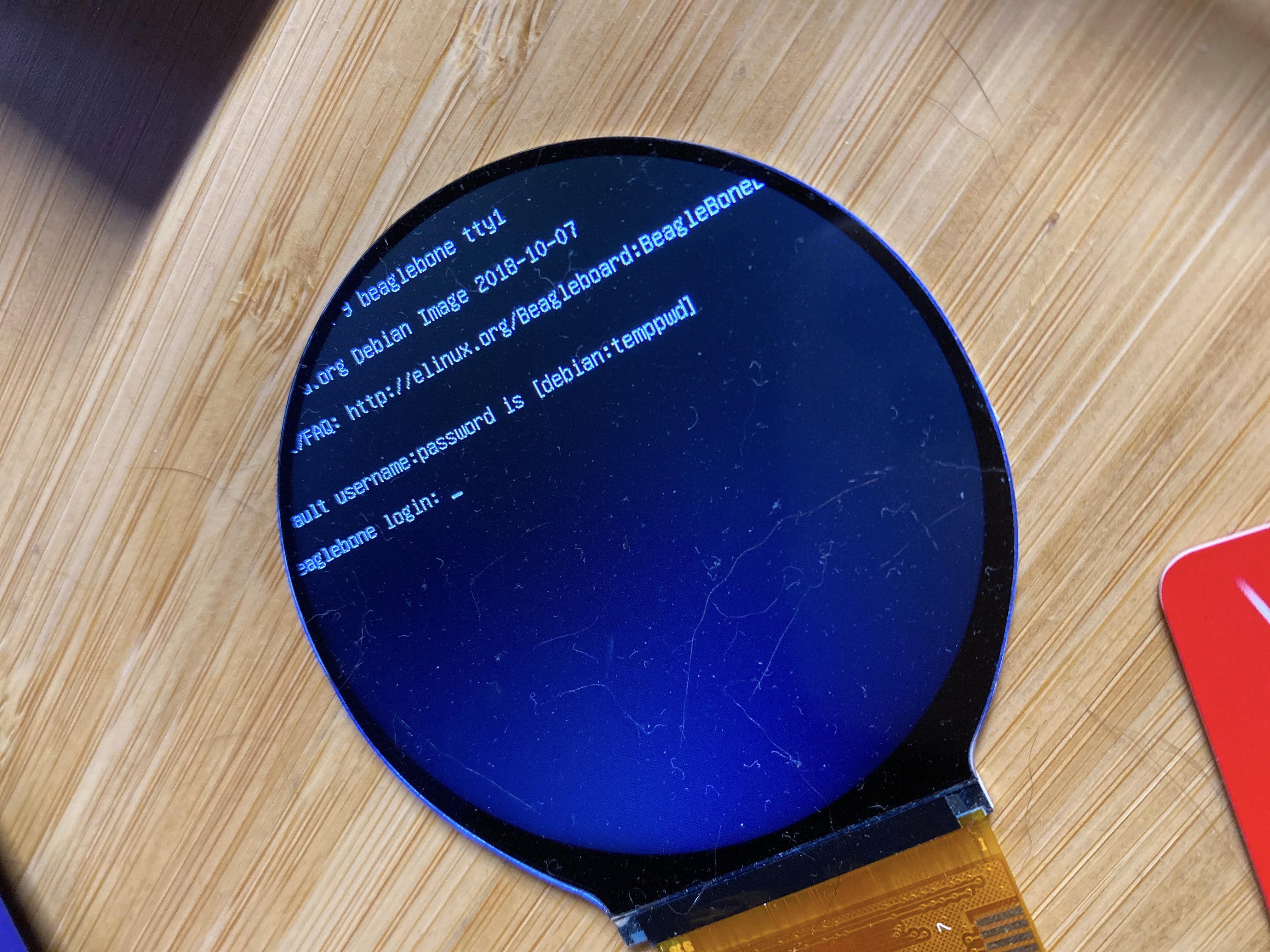
Using fim to render a pure white png produces this:
IMG_6400

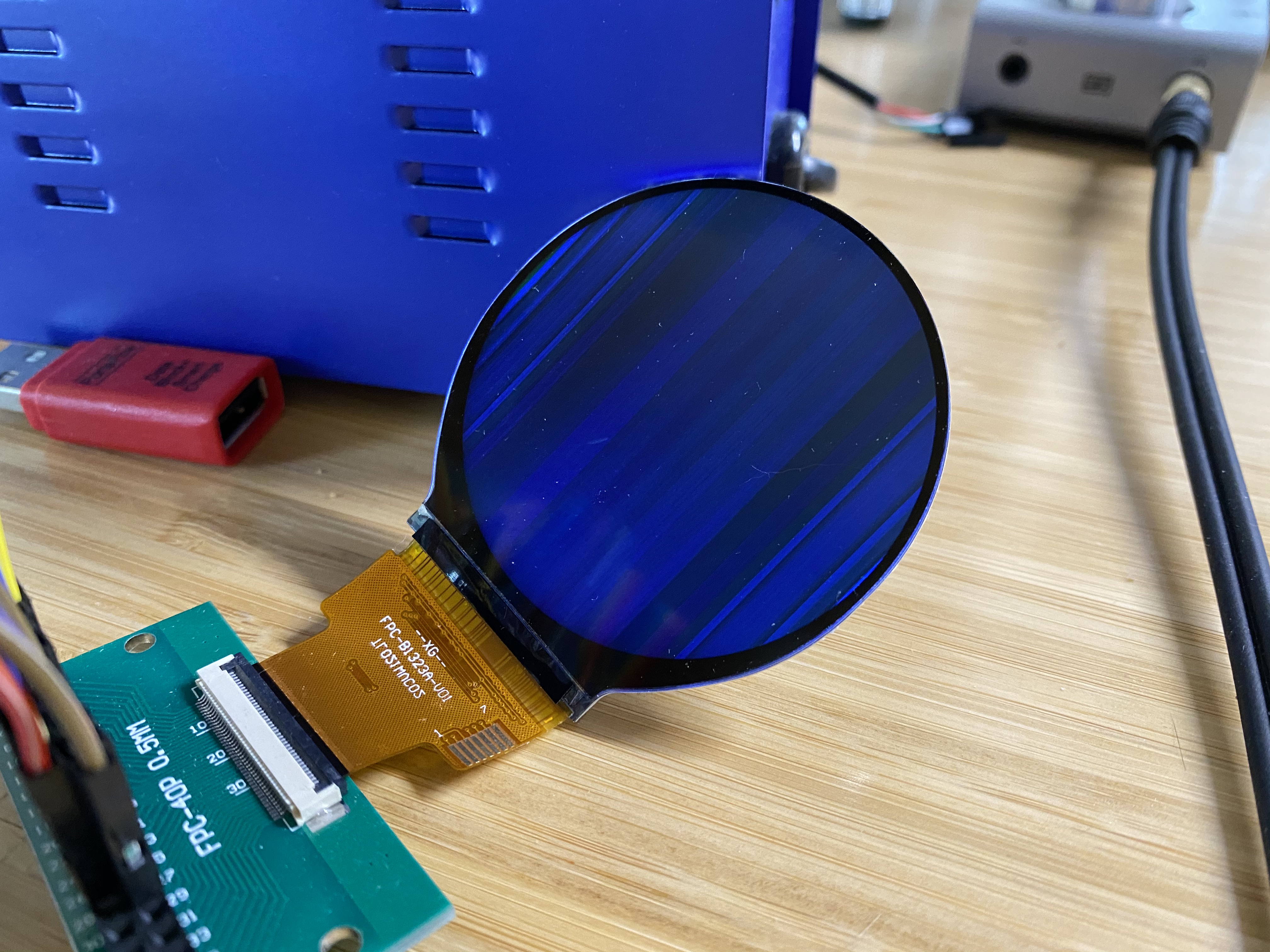
The OS is Debian Stretch 9.5 IoT from the Beaglebone website.

The display is connected as per the normal 

The chosen resolution is 480x480@60Hz. I've also tried the CVT RB and CVT RBv2 variants of standard VGA (640x480@60Hz, which should be supported by the ST7701S), and the results are the same, just shifted on the display. All tested configurations are visible in the device tree overlay.

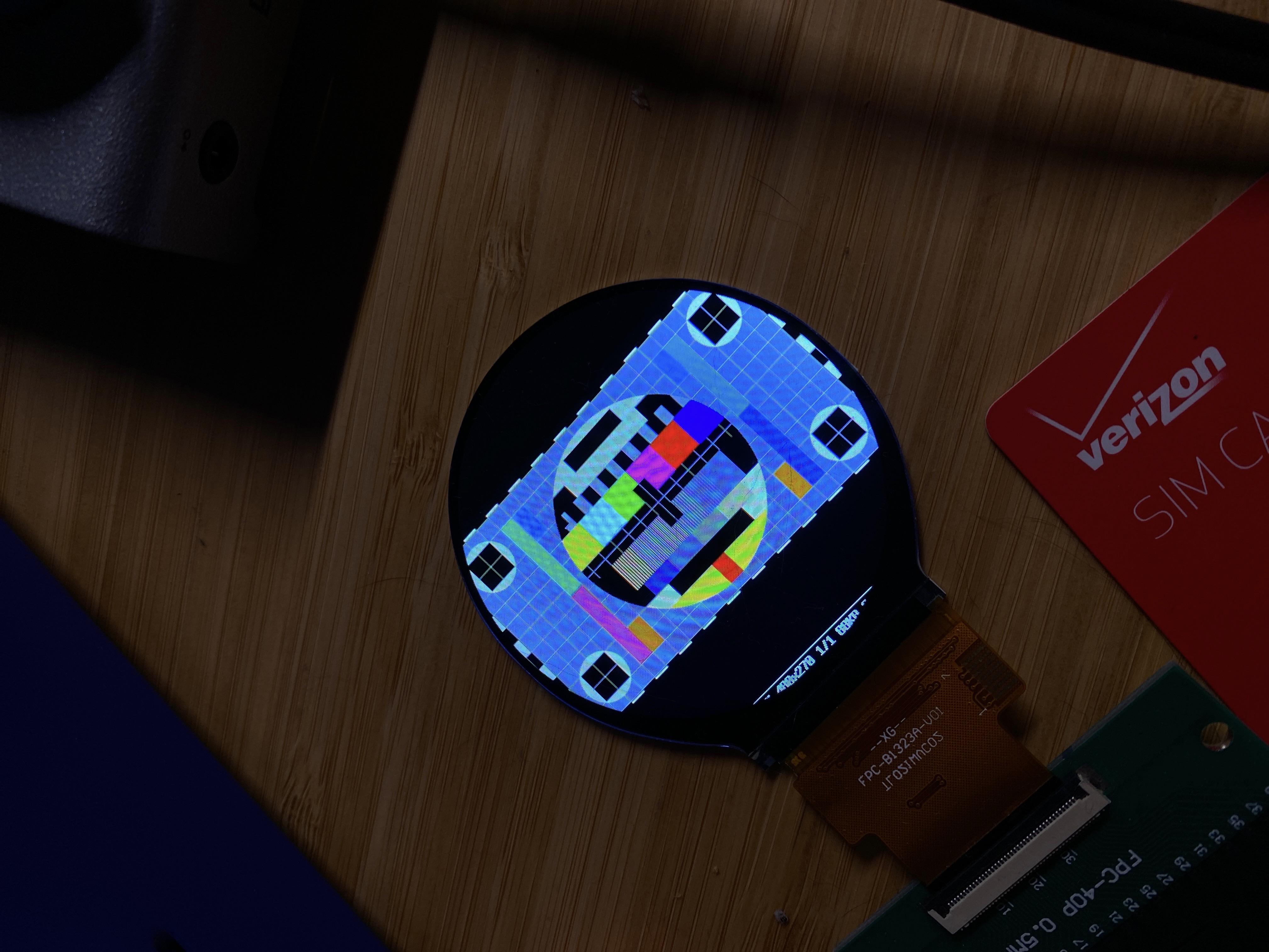
Using fim to display other test images produces similar results. My pure black png is dark, a color test pattern produces some green effects, etc.

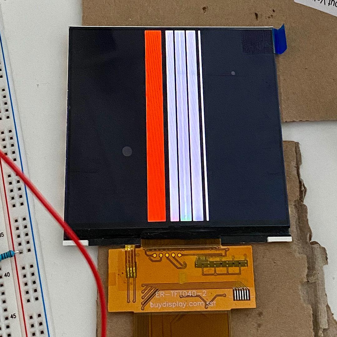
Testing the signal lines with a logic analyzer shows the expected values when sampling the MSB for each color. An excellent example is using a test image like this:
image004

When zoomed to the level of a single frame, everything looks correct, like the datasheet. DE, VSYNC, and HSYNC polarity look good and correct. The VSYNC refresh rate tested at 59.97hz, which should be appropriate for the display.
image005

When I zoom in to look at the timings for each line, everything also looks correct, and you can see the white and black pattern for each line in the MSB values. My logic analyzer can only sample as fast as 24MS/s, which does not accurately capture the pixel clock (which is was set to 16.15MHz for this test).
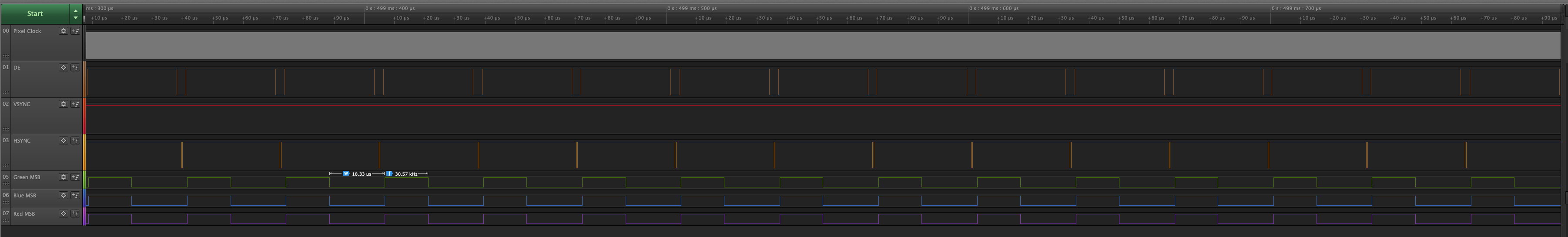
image006

Relevant files:


Here is the exact hardware setup I'm using:
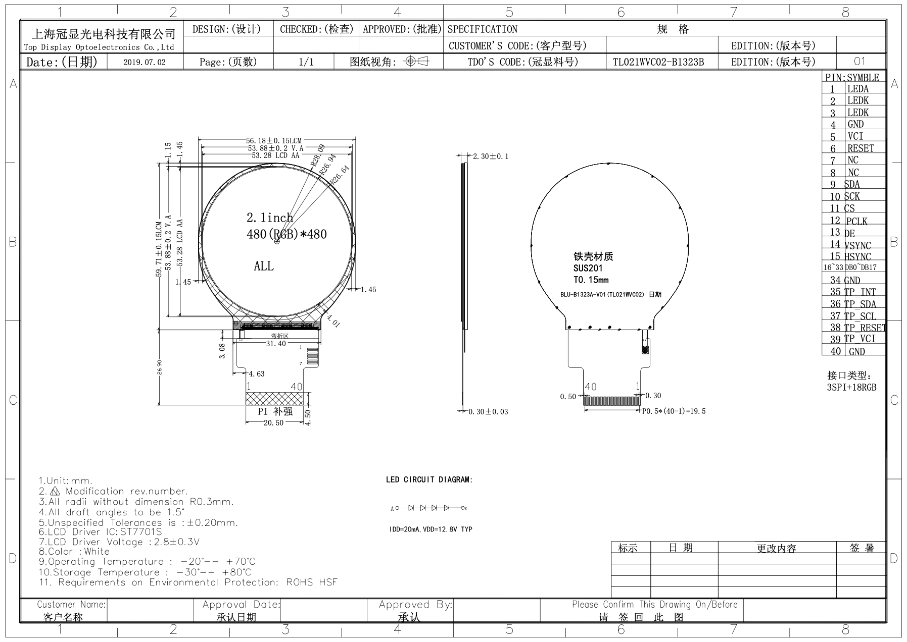
IMG_6401

Screen Shot 2020-03-30 at 10 46 23 AM

FunctionNamePinResistorPinName
LED ANODE+12.8vDC PSU +--1LED A
LED CATHODEGNDDC PSU ---2LED K
LED CATHODEGNDDC PSU ---3LED K
GroundDGNDP9.1--4GND
Power supplyVDD 3.3VP9.3--5VCI
Reset SignalGPIO_60P9.12--6RESET
Not Connected------7NC
Not Connected------8NC
SPI Data signalSPIO_D1P9.18--9SDA
SPI Clock signalSPIO_SLCKP9.22--10SCK
SPI Chip select signalSPIO_CSOP9.17--11CS
RGB dot clock signalLCD_PCLKP8.2833Ω12PCLK
RGB data enable signalLCD_AC_BIASP8.3033Ω13DE
RGB frame synchronizing signalLCD_VSYNCP8.2733Ω14VSYNC
RGB line synchronizing signalLCD_HSYNCP8.2933Ω15HSYNC
📘B[0]DGNDP8.133Ω16DB0
📘B[1]LCD_DATA0P8.4533Ω17DB1
📘B[2]LCD_DATA1P8.4633Ω18DB2
📘B[3]LCD_DATA2P8.4333Ω19DB3
📘B[4]LCD_DATA3P8.4433Ω20DB4
📘B[5]LCD_DATA4P8.4133Ω21DB5
📗G[0]LCD_DATA5P8.4233Ω22DB
📗G[1]LCD_DATA6P8.3933Ω23DB
📗G[2]LCD_DATA7P8.4033Ω24DB
📗G[3]LCD_DATA8P8.3733Ω25DB
📗G[4]LCD_DATA9P8.3833Ω26DB
📗G[5]LCD_DATA10P8.3633Ω27DB
📕R[0]DGNDP8.233Ω28DB
📕R[1]LCD_DATA11P8.3433Ω29DB
📕R[2]LCD_DATA12P8.3533Ω30DB
📕R[3]LCD_DATA13P8.3333Ω31DB
📕R[4]LCD_DATA14P8.3133Ω32DB
📕R[5]LCD_DATA15P8.3333Ω33DB

Robert Forsyth

unread,
Mar 30, 2020, 8:02:43 PM3/30/20
to BeagleBoard
The SPI has a command or data address, the data sheet says there is 4 wire SPI with signal for C/D address and 8 bit SPI words, otherwise 3 wire SPI with 9 bit SPI words where the first bit is C/D address. Are you handling commands with data-parameters? There are also 16 bit SPI words, which seems easier to use. The IM mode also selects MIPI or RGB mode.

The default ST7701S setting for  number of lines, appears to be 863, give an HSYNC of approximately 51.75 kHz and pixel clock of 30 MHz.

For 480 by ~510, dot clock 17.6 MHz
The VSYNC/HSYNC and pixels look right, except near the end of the frame/field.

How do you know what the LCD drive voltages are? Are they setup in the display's ROM for you?

rap...@productionbuild.de

unread,
May 3, 2020, 12:08:11 AM5/3/20
to BeagleBoard
I've got the exact same issue with a 480x480px display controlled by an ST7701S - not related to a BeagleBoard, though. I've got the display hooked up to a custom PCB and I'm also using the RGB interface and the 8-bit SPI. I'm fairly confident that my commands (including parameters) sent to the ST7701S get interpreted properly as the display responds as expected to at least some of them. I've measured all the signals (hsync, vsync, de, rgb) multiple times and they seem to be in order.

I always get the same effect as described by the OP: every line is looking the same. I've got full control over the x-axis, however, and can even run animations.

IMG2.jpg


I'm posting this mostly for documentation purposes and I'll post updates should I ever manage to resolve the issue.
In the meantime, if anyone has any suggestions on what might be causing this I'm more than happy to hear them.

Robert Forsyth

unread,
May 3, 2020, 6:44:31 AM5/3/20
to BeagleBoard
The Densitron DMT040QBHTNT0-1A data sheet has much useful info.
DE Mode:
VS and HS are inverted (active low)
DE and DOTCLK (active-high)

HV Mode:
VS and HS are active-low
PCLK active-high
DE always 1

SPI:
SPI has 4 clock modes
SCK/SCL is active-high (normally low on fall of active-low CS)
clocks data in on first rising edge
clocks data out on first falling edge after first rising edge


On Monday, 30 March 2020 22:34:30 UTC+1, Corey Vixie wrote:

Robert Forsyth

unread,
May 3, 2020, 6:53:14 AM5/3/20
to BeagleBoard
What I was trying to say, if VS or HS change as the PCLK is rising, then it may not register, but the next PCLK clock should register the VS or HS

rap...@productionbuild.de

unread,
May 3, 2020, 10:26:09 AM5/3/20
to BeagleBoard

What I was trying to say, if VS or HS change as the PCLK is rising, then it may not register, but the next PCLK clock should register the VS or HS

Good point! In my case, the VS and HS signals are generated on the PCLK's falling edge though, so they should be valid on the next rising edge of the PCLK. I just measured again to verify. That being said, I also suspect the frame sync being off somehow and I've been exploring this possibility in detail and will continue to do so.

Corey Vixie

unread,
May 3, 2020, 1:09:41 PM5/3/20
to BeagleBoard
All, sorry for my slow response - I've just seen the comments on the GitHub issue and will mirror my findings there.

I always get the same effect as described by the OP: every line is looking the same. I've got full control over the x-axis, however, and can even run animations.

I'm happy to say that I've solved it. Or, rather, that I had a solution provided to me. What you're describing (and your images) seem extremely similar to some of the failure modes I was observing, and I likewise found next to nothing online about this. Plenty for the ST7701, which is apparently just different enough.

camphoto_341603450.jpeg 

camphoto_959030623.jpeg


The short answer is one that should frustrate you, especially if you were using the same Sitronix data sheet that I was: NOT ALL OF THE COMMANDS ARE LISTED IN THE DATASHEET

I ended up emailing my contact at Shanghai TDO, and she shared with me the init sequence that their engineers use:

#if 1 //zheng shao
SPI_WriteComm(0xFF);
SPI_WriteData(0x77);
SPI_WriteData(0x01);
SPI_WriteData(0x00);
SPI_WriteData(0x10);

SPI_WriteComm(0xC0);
SPI_WriteData(0x3B);
SPI_WriteData(0x00);

SPI_WriteComm(0xC1);
SPI_WriteData(0x0B); //VBP
SPI_WriteData(0x02);

SPI_WriteComm(0xC2);
SPI_WriteData(0x00);
SPI_WriteData(0x02);

SPI_WriteComm(0xCC);
SPI_WriteData(0x10);

SPI_WriteComm(0xCD);
SPI_WriteData(0x08);


SPI_WriteComm ( 0xB0); //Positive Voltage Gamma Control  
SPI_WriteData ( 0x02); 
SPI_WriteData ( 0x13);
SPI_WriteData ( 0x1B);
SPI_WriteData ( 0x0D);
SPI_WriteData ( 0x10);
SPI_WriteData ( 0x05);
SPI_WriteData ( 0x08);
SPI_WriteData ( 0x07);
SPI_WriteData ( 0x24);
SPI_WriteData ( 0x04);
SPI_WriteData ( 0x11);
SPI_WriteData ( 0x0E);
SPI_WriteData ( 0x2C);
SPI_WriteData ( 0x33);
SPI_WriteData ( 0x1D);

SPI_WriteComm ( 0xB1); //Negative Voltage Gamma Control  
SPI_WriteData ( 0x05); 
SPI_WriteData ( 0x13);
SPI_WriteData ( 0x1B);
SPI_WriteData ( 0x0D);
SPI_WriteData ( 0x11);
SPI_WriteData ( 0x05);
SPI_WriteData ( 0x08);
SPI_WriteData ( 0x07);
SPI_WriteData ( 0x24);
SPI_WriteData ( 0x04);
SPI_WriteData ( 0x11);
SPI_WriteData ( 0x0E);
SPI_WriteData ( 0x2C);
SPI_WriteData ( 0x33);
SPI_WriteData ( 0x1D);

SPI_WriteComm(0xFF);
SPI_WriteData(0x77);
SPI_WriteData(0x01);
SPI_WriteData(0x00);
SPI_WriteData(0x11);

SPI_WriteComm(0xB0);   
SPI_WriteData(0x5d);//5d
 
SPI_WriteComm(0xB1); //VCOM amplitude setting  
SPI_WriteData(0x43); //43
  
SPI_WriteComm(0xB2); //VGH Voltage setting  
SPI_WriteData(0x81); //12V

SPI_WriteComm(0xB3);
SPI_WriteData(0x80);

SPI_WriteComm(0xB5); //VGL Voltage setting  
SPI_WriteData(0x43); //-8.3V

SPI_WriteComm(0xB7);
SPI_WriteData(0x85);

SPI_WriteComm(0xB8);
SPI_WriteData(0x20);

SPI_WriteComm(0xC1);
SPI_WriteData(0x78);

SPI_WriteComm(0xC2);
SPI_WriteData(0x78);

SPI_WriteComm(0xD0);
SPI_WriteData(0x88);

SPI_WriteComm(0xE0);
SPI_WriteData(0x00);
SPI_WriteData(0x02);

SPI_WriteComm(0xE1);
SPI_WriteData(0x03);
SPI_WriteData(0xA0);
SPI_WriteData(0x00);
SPI_WriteData(0x04);
SPI_WriteData(0xA0);
SPI_WriteData(0x00);
SPI_WriteData(0x20);

SPI_WriteComm(0xE2);
SPI_WriteData(0x00);
SPI_WriteData(0x00);  
SPI_WriteData(0x00);

SPI_WriteComm(0xE3);
SPI_WriteData(0x00);
SPI_WriteData(0x11);
SPI_WriteData(0x00);

SPI_WriteComm(0xE4);
SPI_WriteData(0x22);
SPI_WriteData(0x00);

SPI_WriteComm(0xE5);
SPI_WriteData(0x05);
SPI_WriteData(0xEC);
SPI_WriteData(0xA0);
SPI_WriteData(0x07);
SPI_WriteData(0xEE);
SPI_WriteData(0xA0);
SPI_WriteData(0x00);

SPI_WriteComm(0xE6);
SPI_WriteData(0x00);
SPI_WriteData(0x11);
SPI_WriteData(0x00);

SPI_WriteComm(0xE7);
SPI_WriteData(0x22);
SPI_WriteData(0x00);

SPI_WriteComm(0xE8);
SPI_WriteData(0x06);
SPI_WriteData(0xED);
SPI_WriteData(0xA0);
SPI_WriteData(0x08);
SPI_WriteData(0xEF);
SPI_WriteData(0xA0); 
SPI_WriteData(0xA0);
SPI_WriteData(0x00);

SPI_WriteComm(0xEB);
SPI_WriteData(0x00);
SPI_WriteData(0x40);
SPI_WriteData(0x00);
SPI_WriteData(0x00);  

SPI_WriteComm(0xED);  
SPI_WriteData(0xFF); 
SPI_WriteData(0xFF);  
SPI_WriteData(0xFF);
SPI_WriteData(0xBA);
SPI_WriteData(0x0A);
SPI_WriteData(0xBF);
SPI_WriteData(0x45);
SPI_WriteData(0xFF); 
SPI_WriteData(0xFF);  
SPI_WriteData(0x54);
SPI_WriteData(0xFB);
SPI_WriteData(0xA0);
SPI_WriteData(0xAB);
SPI_WriteData(0xFF); 

SPI_WriteComm(0xEF);
SPI_WriteData(0x10); 
SPI_WriteData(0x0D); 
SPI_WriteData(0x04); 
SPI_WriteData(0x08); 
SPI_WriteData(0x3F); 
SPI_WriteData(0x1F);

SPI_WriteComm(0xFF);
SPI_WriteData(0x77);
SPI_WriteData(0x01);
SPI_WriteData(0x00);
SPI_WriteData(0x13);

SPI_WriteComm(0xEF);
SPI_WriteData(0x08);

SPI_WriteComm(0xFF);
SPI_WriteData(0x77);
SPI_WriteData(0x01);
SPI_WriteData(0x00);

#if 0
WriteComm (0xFF);
WriteData (0x77);
WriteData (0x01);
WriteData (0x00);
WriteData (0x00);
WriteData (0x12);
WriteComm (0xD1);
WriteData (0x81);
WriteData (0x08);
WriteData (0x03);
WriteData (0x20);
WriteData (0x08);
WriteData (0x01);
WriteData (0xA0);
WriteData (0x01);
WriteData (0xE0);
WriteData (0xA0);
WriteData (0x01);
WriteData (0xE0);
WriteData (0x03);
WriteData (0x20);
WriteComm (0xD2);
WriteData (0x08);
#endif
/////////////////Bring up the internal test picture///////////////////////////////////


SPI_WriteComm(0x11);

Delay(120);

SPI_WriteComm(0x29);

SPI_WriteComm(0x36);
SPI_WriteData(0x00);

SPI_WriteComm(0x3A);
SPI_WriteData(0x60);//0x60 18bit   0x50 16bit
#endif


I translated the commands that I was able to look up, but there's a HUGE block of them that are nowhere in the docs, so I just sent them blind: https://github.com/ironblock/ST7701S-SPI-Driver/blob/master/src/sequence_tdo.rs#L75-L139

So ultimately, I have no idea what's in those commands that could be so critical to a ST7701S display working that it wouldn't be in the datasheet for the chip, but evidently the "unscramble display and make it actually work" command is somewhere in there.

Please let me know if you try this, and let me know if it works for you.

rap...@productionbuild.de

unread,
May 4, 2020, 3:04:40 AM5/4/20
to BeagleBoard
Thank you very much for your reply! I tested the command sequence you posted and only changed the porch control to fit my timings. The output has changed now but I can't really tell whether it's become worse or better. I also tried the internal test image and it does look nothing like the test image you posted and it's still all the same on every line:

IMG4.jpg


I think I'll need to get in touch with the manufacturer of my display or even look for an alternative.

Just out of curiosity, do you know what happens when the porch control setting is off?

rap...@productionbuild.de

unread,
May 7, 2020, 3:49:08 AM5/7/20
to BeagleBoard
So, I got in contact with the vendor and apparently this is the right command sequence for my display:

SPI_WriteComm (0x11);
delay
(300);
SPI_WriteComm
(0xFF);
SPI_WriteData
(0x77);
SPI_WriteData
(0x01);
SPI_WriteData
(0x00);
SPI_WriteData
(0x00);
SPI_WriteData
(0x10);
SPI_WriteComm
(0xC0);
SPI_WriteData
(0x3B);
SPI_WriteData
(0x00);
SPI_WriteComm
(0xC1);
SPI_WriteData
(0x0D);
SPI_WriteData
(0x02);
SPI_WriteComm
(0xC2);
SPI_WriteData
(0x21);
SPI_WriteData
(0x08);
SPI_WriteComm
(0xB0);
SPI_WriteData
(0x00);
SPI_WriteData
(0x11);
SPI_WriteData
(0x18);
SPI_WriteData
(0x0E);
SPI_WriteData
(0x11);
SPI_WriteData
(0x06);
SPI_WriteData
(0x07);
SPI_WriteData
(0x08);
SPI_WriteData
(0x07);
SPI_WriteData
(0x22);
SPI_WriteData
(0x04);
SPI_WriteData
(0x12);
SPI_WriteData
(0x0F);
SPI_WriteData
(0xAA);
SPI_WriteData
(0x31);
SPI_WriteData
(0x18);
SPI_WriteComm
(0xB1);
SPI_WriteData
(0x00);
SPI_WriteData
(0x11);
SPI_WriteData
(0x19);
SPI_WriteData
(0x0E);
SPI_WriteData
(0x12);
SPI_WriteData
(0x07);
SPI_WriteData
(0x08);
SPI_WriteData
(0x08);
SPI_WriteData
(0x08);
SPI_WriteData
(0x22);
SPI_WriteData
(0x04);
SPI_WriteData
(0x11);
SPI_WriteData
(0x11);
SPI_WriteData
(0xA9);
SPI_WriteData
(0x32);
SPI_WriteData
(0x18);
SPI_WriteComm
(0xFF);
SPI_WriteData
(0x77);
SPI_WriteData
(0x01);
SPI_WriteData
(0x00);
SPI_WriteData
(0x00);
SPI_WriteData
(0x11);
SPI_WriteComm
(0xB0);
SPI_WriteData
(0x60);
SPI_WriteComm
(0xB1);
SPI_WriteData
(0x30);
SPI_WriteComm
(0xB2);
SPI_WriteData
(0x87);
SPI_WriteComm
(0xB3);
SPI_WriteData
(0x80);
SPI_WriteComm
(0xB5);
SPI_WriteData
(0x49);
SPI_WriteComm
(0xB7);
SPI_WriteData
(0x85);
SPI_WriteComm
(0xB8);
SPI_WriteData
(0x21);
SPI_WriteComm
(0xC1);
SPI_WriteData
(0x78);
SPI_WriteComm
(0xC2);
SPI_WriteData
(0x78);
delay
(20);
SPI_WriteComm
(0xE0);
SPI_WriteData
(0x00);
SPI_WriteData
(0x1B);
SPI_WriteData
(0x02);
SPI_WriteComm
(0xE1);
SPI_WriteData
(0x08);
SPI_WriteData
(0xA0);
SPI_WriteData
(0x00);
SPI_WriteData
(0x00);
SPI_WriteData
(0x07);
SPI_WriteData
(0xA0);
SPI_WriteData
(0x00);
SPI_WriteData
(0x00);
SPI_WriteData
(0x00);
SPI_WriteData
(0x44);
SPI_WriteData
(0x44);
SPI_WriteComm
(0xE2);
SPI_WriteData
(0x11);
SPI_WriteData
(0x11);
SPI_WriteData
(0x44);
SPI_WriteData
(0x44);
SPI_WriteData
(0xED);
SPI_WriteData
(0xA0);
SPI_WriteData
(0x00);
SPI_WriteData
(0x00);
SPI_WriteData
(0xEC);
SPI_WriteData
(0xA0);
SPI_WriteData
(0x00);
SPI_WriteData
(0x00);
SPI_WriteComm
(0xE3);
SPI_WriteData
(0x00);
SPI_WriteData
(0x00);
SPI_WriteData
(0x11);
SPI_WriteData
(0x11);
SPI_WriteComm
(0xE4);
SPI_WriteData
(0x44);
SPI_WriteData
(0x44);
SPI_WriteComm
(0xE5);
SPI_WriteData
(0x0A);
SPI_WriteData
(0xE9);
SPI_WriteData
(0xD8);
SPI_WriteData
(0xA0);
SPI_WriteData
(0x0C);
SPI_WriteData
(0xEB);
SPI_WriteData
(0xD8);
SPI_WriteData
(0xA0);
SPI_WriteData
(0x0E);
SPI_WriteData
(0xED);
SPI_WriteData
(0xD8);
SPI_WriteData
(0xA0);
SPI_WriteData
(0x10);
SPI_WriteData
(0xEF);
SPI_WriteData
(0xD8);
SPI_WriteData
(0xA0);
SPI_WriteComm
(0xE6);
SPI_WriteData
(0x00);
SPI_WriteData
(0x00);
SPI_WriteData
(0x11);
SPI_WriteData
(0x11);
SPI_WriteComm
(0xE7);
SPI_WriteData
(0x44);
SPI_WriteData
(0x44);
SPI_WriteComm
(0xE8);
SPI_WriteData
(0x09);
SPI_WriteData
(0xE8);
SPI_WriteData
(0xD8);
SPI_WriteData
(0xA0);
SPI_WriteData
(0x0B);
SPI_WriteData
(0xEA);
SPI_WriteData
(0xD8);
SPI_WriteData
(0xA0);
SPI_WriteData
(0x0D);
SPI_WriteData
(0xEC);
SPI_WriteData
(0xD8);
SPI_WriteData
(0xA0);
SPI_WriteData
(0x0F);
SPI_WriteData
(0xEE);
SPI_WriteData
(0xD8);
SPI_WriteData
(0xA0);
SPI_WriteComm
(0xEB);
SPI_WriteData
(0x02);
SPI_WriteData
(0x00);
SPI_WriteData
(0xE4);
SPI_WriteData
(0xE4);
SPI_WriteData
(0x88);
SPI_WriteData
(0x00);
SPI_WriteData
(0x40);
SPI_WriteComm
(0xEC);
SPI_WriteData
(0x3C);
SPI_WriteData
(0x00);
SPI_WriteComm
(0xED);
SPI_WriteData
(0xAB);
SPI_WriteData
(0x89);
SPI_WriteData
(0x76);
SPI_WriteData
(0x54);
SPI_WriteData
(0x02);
SPI_WriteData
(0xFF);
SPI_WriteData
(0xFF);
SPI_WriteData
(0xFF);
SPI_WriteData
(0xFF);
SPI_WriteData
(0xFF);
SPI_WriteData
(0xFF);
SPI_WriteData
(0x20);
SPI_WriteData
(0x45);
SPI_WriteData
(0x67);
SPI_WriteData
(0x98);
SPI_WriteData
(0xBA);
SPI_WriteComm
(0xFF);
SPI_WriteData
(0x77);
SPI_WriteData
(0x01);
SPI_WriteData
(0x00);
SPI_WriteData
(0x00);
SPI_WriteData
(0x00);
SPI_WriteComm
(0x29);


It does work! My issue is resolved.

Hao Yuin

unread,
Sep 14, 2020, 9:06:33 AM9/14/20
to BeagleBoard
i have similar round LCD screen but still fail to bring it up.  The Linux MIPI DSI driver will never work for the ST7701??  I tried modify panel-raydium-rm67191.c and add in these command sequence. No errors but still cannot get good image. Maybe my timing also out. May I know the timing (hfp, hbp, hsync, vfp, vbp, vsync) you are using? 

H. Nikolaus Schaller

unread,
Sep 14, 2020, 9:20:23 AM9/14/20
to beagl...@googlegroups.com

> Am 14.09.2020 um 10:23 schrieb Hao Yuin <hao...@gmail.com>:
>
> i have similar round LCD screen but still fail to bring it up. The Linux MIPI DSI driver will never work for the ST7701?? I tried modify panel-raydium-rm67191.c and add in these command sequence. No errors but still cannot get good image. Maybe my timing also out. May I know the timing (hfp, hbp, hsync, vfp, vbp, vsync) you are using?


AFAIK, omaprm does not (yet) support drm/panel for DSI panels (only DPI). It supports only panels in drm/omapdrm/displays.
There was a patch series posted a while ago by Sebastian Reichel to fix this but it is not yet reviewed and merged. So I would not expect it to arrive before v5.12 or v5.13...

For the meantime we have a MIPI-DSI panel running on omap5 (with v5.9):
https://git.goldelico.com/?p=letux-kernel.git;a=shortlog;h=refs/heads/letux/boe-w677-dsi-panel

We plan to move and update it for drm/panel which should not be too difficult but too early.

-- hns

Daniil Savchenko

unread,
Jun 18, 2021, 9:39:38 AM6/18/21
to BeagleBoard
Could you share a link to your project? Now I'm trying to figure it out, and so far it's not working out very well (not everything is in the documentation). I think it would be helpful. Thank you.

понедельник, 4 мая 2020 г. в 10:04:40 UTC+3, rap...@productionbuild.de:

Daniil Savchenko

unread,
Jun 18, 2021, 9:39:38 AM6/18/21
to BeagleBoard
Could you share a link to your project? Now I'm trying to figure it out, and so far it's not working out very well (not everything is in the documentation). I think it would be helpful. Thank you.

четверг, 7 мая 2020 г. в 10:49:08 UTC+3, rap...@productionbuild.de:

Corey Vixie

unread,
Jun 18, 2021, 3:06:20 PM6/18/21
to BeagleBoard
Hi Daniil,


I tried to document the build steps as thoroughly as possible, but please let me know if I’ve missed something or if there are any questions I can answer.

I do all my development work in macOS (running Ubuntu in Vagrant), and the target is always a Rev C BeagleBone Black, running the Debian 9.12 ImgTec image from https://beagleboard.org/latest-images

I don’t have access to the hardware at this exact moment, but I can check various settings later. I don’t remember if I updated to Debian 10 on that board, but I may have. Unfortunately, the chip shortage kind of paused all my development, but I’m happy to help anyone who can make use of this code.

Pull requests, comments, questions welcome ☺️

Raphael Stäbler

unread,
Jun 21, 2021, 3:56:46 AM6/21/21
to BeagleBoard
Hi Daniil,


It's open source and fairly well documented.
Reply all
Reply to author
Forward
0 new messages