CV Input (1V/OCT)

685 views
Skip to first unread message

j

unread,
Apr 17, 2015, 8:57:59 AM4/17/15
to axolot...@googlegroups.com

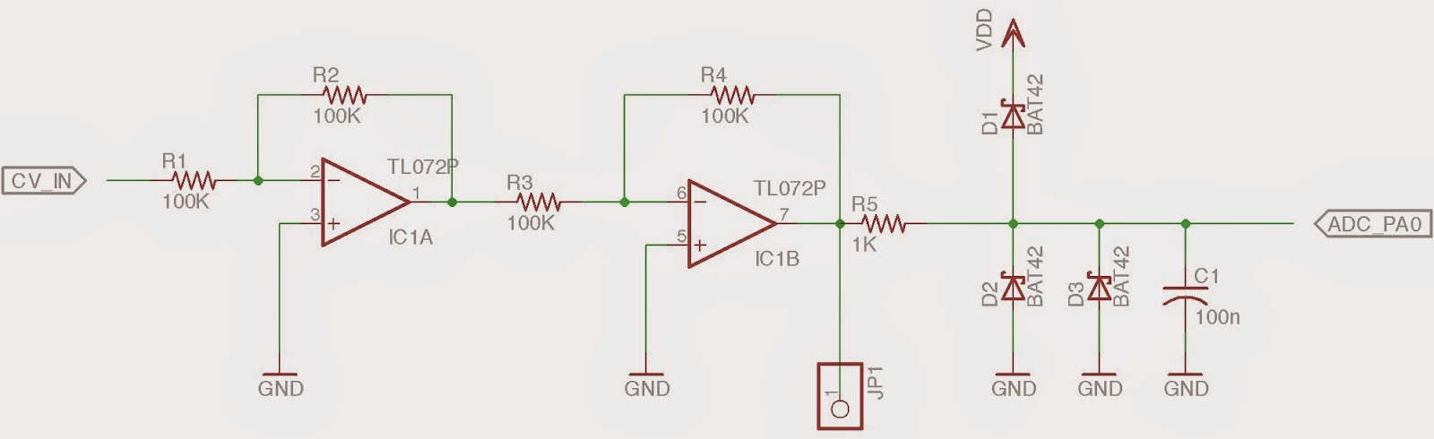
does anyone can tell me, how to scale an ADC measured voltage (0-5V) to 1V/Oct? Inspired by Music Thing "Radio Music" module, I create a circuit example, where a 5V input voltage should be divide by 2 to ensure, it will measure the full 5V input. VDD can be may vary from ideal 3V.

Resistors are all 1% tolerance.

  • R8 = precision trimmer 
  • R7 = line potentiometer to attenuate input
  • Diodes (D1,2,3,4) = shottky diodes (ensure, that input is limited to 0-VDD (3V).)

Some DVCOs like Mutable Instruments Braids use a digital calibration processing. Therefore you have to insert a 1V and then a 3V as reference to do the 1V/Oct math. It would be ideal, if the calibrated datas would be safe at the internal flash or SD card. I'm very new to the ARM microprocessor. I'm not much skilled with coding. Mainly, I use Arduinos and Max/MSP.


Johannes Taelman

unread,
Apr 17, 2015, 10:33:40 AM4/17/15
to j, axolot...@googlegroups.com
The gpio/analog object outputs a "fraction" where 64 units is full scale, corresponding to 3.3V.
If it would be an analog modular, Axoloti uses 1U/semitone scaling in the patcher, where -64 to 64 is the full range.
So 1 volt at an analog input will result in 64/3.3 units = 19.39 units. With a "math/*c" you can scale this down to 1U/semitone by adjusting the dial to 3.3U. Press the shift key to adjust a parameter in sub-unit steps by mouse. Or type the value followed by enter when the parameter is focused.

I haven't looked into using calibrated voltage references. There is an internal voltage reference in the processor available for the ADC, but from the specs it does not seem to be very accurate: min 1.18V, typical 1.21V, max 1.24V... Maybe good to also connect an external 1V reference to the ADC. Both a 1V and 3V reference sounds a bit overkill to me, I'd expect linearity of the convertor to be fair enough.

I'd increase the value of the 47R output resistor to 470R, such low value 'd drive a lot of current, overloading the opamp or the shottkys.

For storing calibration data, there is more things that could go into like a "system setup patch", for instance abstracting control inputs to make patches more exchangeable across different setups. That's not there yet.


--
You received this message because you are subscribed to the Google Groups "axoloti-users" group.
To unsubscribe from this group and stop receiving emails from it, send an email to axoloti-user...@googlegroups.com.
To post to this group, send email to axolot...@googlegroups.com.
To view this discussion on the web visit https://groups.google.com/d/msgid/axoloti-users/e5a63a9f-0048-4951-b662-631c9bc8cae1%40googlegroups.com.
For more options, visit https://groups.google.com/d/optout.

Alexander Steen

unread,
Apr 17, 2015, 10:38:07 AM4/17/15
to axolot...@googlegroups.com
hi j,
do you mean you have a device that generates 0V-5V ranged analog signals (1V/Oct) and you want to scale them down to 0V-3V so the axoloti ADC can measure it? And then have te axoloti figure out what frequency the signal corresponds to accurately?

Do you know the output impedance of the signal source? You might be able to get away with a simple voltage divider without opamp, maybe add some capacitance to the adc input. Only if that doesn't work well i would add a voltage follower. The voltage follower schematic should look like this: http://www.electronics-micros.com/img/electronics/voltage-follower1.jpg . I don't think your current schematic would work.

Then you could do a callibration either with a pot as in your schematic or in an axoloti patch.
If you have to choose an opamp for the voltage follower, keep an eye on the input voltage offset in the datasheet as it will be added to the output. For example: a 5mV offset would correspond to a 1/10th seminote if you map 5 octaves to 3V.

hope this helps,
great music on iriemovement btw :)

kind regards,
alex


Op vrijdag 17 april 2015 14:57:59 UTC+2 schreef j:

j

unread,
Apr 17, 2015, 5:48:20 PM4/17/15
to axolot...@googlegroups.com
Thank you Johannes & Alex.
I tested the circuit with a stm32f4 disco. I consider all your comments and build a new test circuit on a breadboard. Output Impedance of most modules should be 1K. I have a look at some circuits from yusynth and muffwiggler forum. Most of them use 100K resistors for input. I'm not an electrician, just little sdiy guy. 

 I used two inverting amplifier. The first inv amp divides the incoming voltage 5V to 3,3V (ideal: R1= 100K, R2+R3=66K). The second one works as a 1:1 inv buffer with offset. The tl072 has 3mV offset. I will test a tl052 with 0,73mV offset, next. An inv amp division should be better to circumvent VDD deviation. When I tested the circuit, there was a strange problem. The diodes don't limit the voltage to 0V & VDD. I measured a min out of -0,430V. Can anybody tell me, why this is happen? 


Johannes Taelman

unread,
Apr 17, 2015, 6:17:29 PM4/17/15
to j, axolot...@googlegroups.com

Diodes have a threshold before they start working, this is normal. And I believe the processor is fine with this, though I didn't verify with the datasheet right now.

--
You received this message because you are subscribed to the Google Groups "axoloti-users" group.
To unsubscribe from this group and stop receiving emails from it, send an email to axoloti-user...@googlegroups.com.
To post to this group, send email to axolot...@googlegroups.com.

Alexander Steen

unread,
Apr 18, 2015, 5:27:31 AM4/18/15
to axolot...@googlegroups.com
your new circuit looks good to me,
alex

Op vrijdag 17 april 2015 23:48:20 UTC+2 schreef j:

Johannes Taelman

unread,
Apr 18, 2015, 8:11:44 AM4/18/15
to j, axolot...@googlegroups.com
The processor datasheet says only 0.3V below ground and 0.3V above supply is tolerated. I suggest replacing your Schottky diodes with a different model with a voltage drop lower than 0.3V.

Jason Nanna

unread,
Apr 18, 2015, 8:58:19 AM4/18/15
to Johannes Taelman, j, axolot...@googlegroups.com
Schottky diodes are going to provide the lowest forward voltage.  I believe that when the datasheet says that .3v above supply / below gnd it means that the protection is a schottky junction.  I'm not certain how much they vary, or how much lower you can get (than your .43v), but remember too that the forward voltage will vary with current and temperature.  The safe thing to do would be to put an additional resistor between the diodes and the ADC. I think the important thing is not to worry about the exact voltage of your protection diodes but rather to worry about where that excess current is flowing.  Depending on the value you select it could increase the impedance of your buffer but assures you that the bulk of the current flows through your external diodes rather than the protection diodes.  Just make sure your resistance is high enough to safely limit the current through any of the diode junctions. 

Also it appears that you're trying to go to some efforts to make this circuit precise.  Offsetting using a pot hanging off of the supply rails will couple any power supply fluctuations into your output.  The precision of your circuit is now more dependent on how clean your supply rails are.  Better solution would be to use an op-amp with an acceptably low offset voltage, or use a voltage reference to generate a bias. 


j

unread,
Apr 18, 2015, 7:30:12 PM4/18/15
to axolot...@googlegroups.com, johannes...@gmail.com, jo...@iriemovement.de
i thought also about a precise voltage reference for offset like a lm4040 or use a precision op amp and invert VDD.  I tested some different voltages with a 1:1 op amp to measure the max/min voltage limits set by diodes and a resistor after R6, like Johannes has said. By experiments, a 2MOhm resistor would drop the voltage enough. Without, the following values are +0,15 higher at positive and 0,15 lower at negative. I used +/-12V to improve, that the diodes will safely protect ADCs. 


stm32f4 disco

VDD = 2,936V

op amp 1:1

  • Input voltage CV In: +12,15V:
  • op amp out voltage: +9.63V
  • ADC max. = +3,0V


  • Input voltage CV In: -11,85V:
  • op amp out voltage: -8,14V
  • ADC min. = -0.316V

======================================

  • Input voltage CV In: +6,016V:
  • op amp out voltage: 6,029V
  • ADC max. = +2,968V


  • Input voltage CV In: -5,911V
  • op amp out voltage: -5,905V
  • ADC min. = -0.296V
Well, the results shows, that the min output of -0,316V is hard at limit for a stm32. I'm very confused, if this diode protection is ideal for axoloti. A lot of my digital modules (Ardcore, Radio Music, Neutron Orgone Accumulator etc.) use this kind of circuit. 

Johannes Taelman

unread,
Apr 19, 2015, 7:35:10 AM4/19/15
to j, axolot...@googlegroups.com
2MOhm after R6 is way too much resistance to drive the ADC properly, the accuracy will suffer a lot. I'd say a few kOhms maximum should do.

In datasheet DM00071990, Section 6.3.16 "I/O current injection characteristics" says you should not inject any negative current into the analog input pins.
They recommend Schottky diodes as the solution. While the 0.3 voltage limit is specified both in section 6.2 "Absolute maximum ratings" as in 6.3.1 "General operating conditions".

Could you maybe measure the current going into the ADC pin when driving it with -0.43V? As Jason said, that is what ultimately matters.

j

unread,
Apr 19, 2015, 9:34:21 AM4/19/15
to axolot...@googlegroups.com, jo...@iriemovement.de
My test circuit:

I removed the 2Mohm resistor and measured follow values:

voltage at JP1= +12,14V

  • after R6 = 3,295V
  • current to ADC = 25,5uA


voltage at JP1= -11,87V

without D3:

  • after R6 = -0.362
  • current to ADC = -93,3uA


with D2+D3:

  • after R6 = -0,325V
  • current to ADC = -48,1uA

Jason Nanna

unread,
Apr 19, 2015, 2:53:38 PM4/19/15
to j, axolot...@googlegroups.com
To prevent the negative excursions, add two diodes to the final amplifier to make a precision rectifier, like so:


Or find a rail-to-rail single-supply op amp that can be powered from 3.3v, and build a buffer using that to guarantee voltage compliance.  Bonus: with this scheme you don't have the added capacitance & leakage of the diodes.


--
You received this message because you are subscribed to the Google Groups "axoloti-users" group.
To unsubscribe from this group and stop receiving emails from it, send an email to axoloti-user...@googlegroups.com.
To post to this group, send email to axolot...@googlegroups.com.

j

unread,
Apr 19, 2015, 5:51:21 PM4/19/15
to axolot...@googlegroups.com, jo...@iriemovement.de
Thank you Jason! The half way rectifier works great and kills all negativ voltage. In a few days, I'm going to buy some missing parts (different op amps, capacitors, lm4040-2,5) at my local electronic shop and test the following circuit. 
I don't know, if diode D4 is necessary.

Jason Nanna

unread,
Apr 25, 2015, 10:18:50 AM4/25/15
to j, axolot...@googlegroups.com
This seems overly complicated to me...   I would suggest using a single-supply inverting op-amp using the STM32 supply voltage and bias it with a negative reference voltage, and then simply flip the response (because it will be inverted) in axoloti.  No need for protection diodes, and if you use a trimmer for gain and for offset you should be able to scale/bias it accurately.  I had the MCP60xx/62xx reccommended for this very application.


On Sun, Apr 19, 2015 at 4:51 PM, j <jo...@iriemovement.de> wrote:
Thank you Jason! The half way rectifier works great and kills all negativ voltage. In a few days, I'm going to buy some missing parts (different op amps, capacitors, lm4040-2,5) at my local electronic shop and test the following circuit. 
I don't know, if diode D4 is necessary.

--
You received this message because you are subscribed to the Google Groups "axoloti-users" group.
To unsubscribe from this group and stop receiving emails from it, send an email to axoloti-user...@googlegroups.com.
To post to this group, send email to axolot...@googlegroups.com.
Reply all
Reply to author
Forward
0 new messages