wiring tricolor LEDs and nosepokes
12 views
Skip to first unread message

Chris Rodgers
Dec 28, 2020, 11:35:57 AM12/28/20
to autopilot-users
I'm about to connect the nosepokes and LEDs to the pi for the first time. When I've done this before, I know there's usually a choice of current-limiting resistor that's important to control the brightness of the LED or the sensitivity of the nosepoke. Is there documentation somewhere on the simple circuit necessary to wire these things up? Is the built-in pull-up/pull-down resistor in the Pi sufficient?
What I have is:
autopilot_default_pinout.pdf (the pin out);
autopilot_electronics_bom.xlsx (the materials, so I know I need 200 ohm resistors and NPN transistors for something);
ports_double_v2_annotated-01.png (an image of a circuit board that probably does what I need)
What would be helpful for me would be something like valve_board.pdf (a circuit schematic for the solenoid valves). Does such a thing exist for the LEDs and nosepokes? Or if not, can someone sort of verbally describe what the circuit is, and I'll figure it out from there?
Bonus question: Last time I set something like this up with a different tweeter, I had to connect a capacitor in series with the tweeter in order to prevent DC (and other low frequencies) from frying the tweeter. Is this recommended for the HiVi? I didn't see it on the datasheet.
Thanks!!
Chris

jlsaun...@gmail.com
Dec 28, 2020, 7:05:30 PM12/28/20
to autopilot-users
To drive RGB LEDs I just use the current from the GPIO pins through resistors (dependent on the forward voltage/current of your LED!):
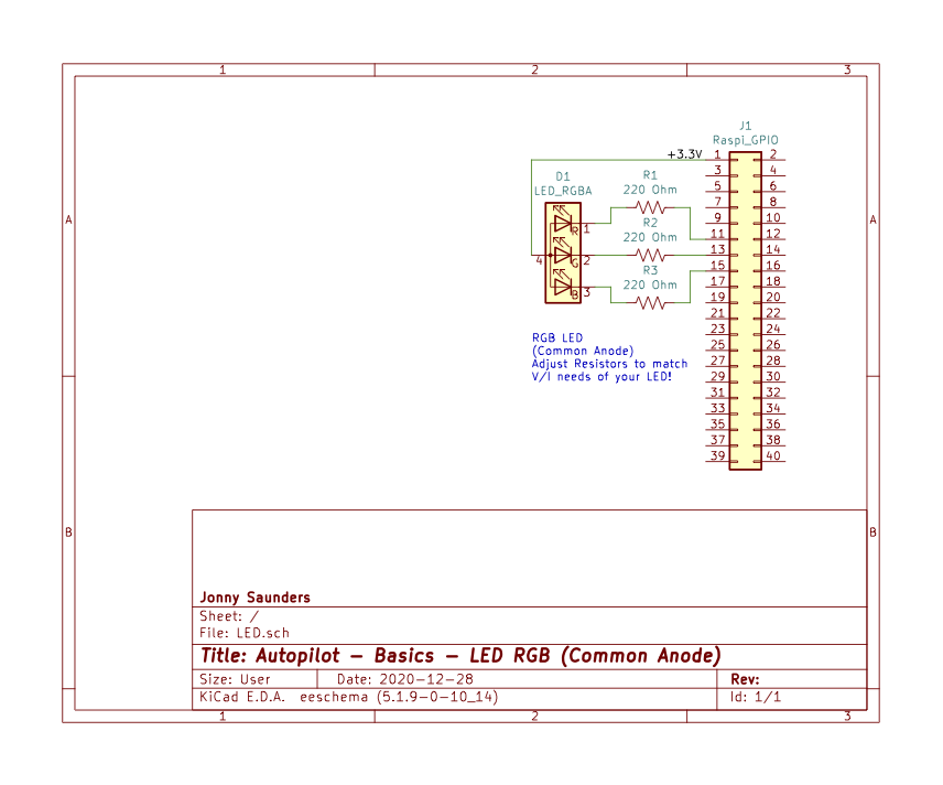
The pins can only source ~16 mA ( https://www.raspberrypi.org/documentation/hardware/raspberrypi/gpio/README.md ) so when I've wanted to use a higher current LED i've just made a simple power transistor circuit from the 5V rail (the little molex annotations are just b/c that's what i use for the connectors but not necessary obvs)
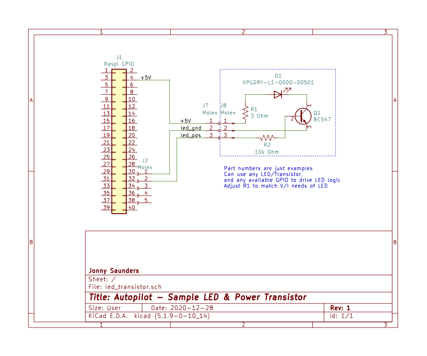
ports_double_v2_annotated-01.png does have the LED circuit I use (with common anode LEDs), but it's sorta unhelpfully embedded within the rest of the poke circuit and hard to read.
I haven't needed to make and special alterations to use the hifiberry, but can't say for certain what would be needed in your system!!
YOU KNOW WHAT LETS MAKE THIS INFORMATION DURABLE I AM SETTING UP THE AUTOPILOT WIKI FOR THIS RIGHT NOW
The pins can only source ~16 mA ( https://www.raspberrypi.org/documentation/hardware/raspberrypi/gpio/README.md ) so when I've wanted to use a higher current LED i've just made a simple power transistor circuit from the 5V rail (the little molex annotations are just b/c that's what i use for the connectors but not necessary obvs)
ports_double_v2_annotated-01.png does have the LED circuit I use (with common anode LEDs), but it's sorta unhelpfully embedded within the rest of the poke circuit and hard to read.
I haven't needed to make and special alterations to use the hifiberry, but can't say for certain what would be needed in your system!!
YOU KNOW WHAT LETS MAKE THIS INFORMATION DURABLE I AM SETTING UP THE AUTOPILOT WIKI FOR THIS RIGHT NOW
jlsaun...@gmail.com
Dec 28, 2020, 7:07:15 PM12/28/20
to autopilot-users
(the resistor values are just examples in both, and typically you want to use a lower resistance for the red LED)
jlsaun...@gmail.com
Dec 28, 2020, 7:55:21 PM12/28/20
to autopilot-users
OK we're live with wiki.auto-pi-lot.com
I'll work on setting up a basic structure over there, drop the info i have on hardware designs/parts lists/etc. and get it started over the next few days.
I'm also going to deprecate this discussion board shortly in favor of using the discussion board on the github repo because it's pretty clunky, not mobile friendly at all & doesn't do code highlighting!?!??!?
Reply all
Reply to author
Forward
Message has been deleted
0 new messages