Custom Element Colors in Circuit Example

46 views
Skip to first unread message

vorp

unread,
Feb 11, 2015, 9:37:13 PM2/11/15
to authoring-to...@googlegroups.com
I'm trying to create some functionality in my app which is based on the Circuit Editor example.
I want to have my Elements (nodes) change color based on property changes in the underlying data.
Such as a "disabled" property making nodes change visually from current to gray.
The closest thing I've found so far is the GetStyle method of IGraphAdaptor that could change the look of circuit elements.
However, if this is the proper route, can styles be edited to accommodate custom states?

Thanks for any pointers as to where to look.

-Len

Ron2

unread,
Feb 12, 2015, 4:37:02 PM2/12/15
to
Hi Len,

Good question! This happened to come up in the last month with another client.

If you upgrade to ATF 3.9 (released on Jan. 29 -- see release notes) and get the changes that I committed to GitHub today, there are two solutions to your problem.

IsValid option
The easier solution, but with fewer customization options, is to set the CircuitElementInfo's IsValid property to 'false', at run-time, to indicate that you want to draw that circuit element with an "error" brush (D2dDiagramTheme.ErrorBrush). You can customize ErrorBrush however you want. The default will look like this:


To see this yourself, you can uncomment the code in CircuitEditorSample.CircuitValidator, in its private ValidateNodes() method. This will cause all circuit elements without a ​name to be marked as "invalid".


Custom D2dDiagramTheme option
You can add a new option on a class that derives from CircuitElementInfo, perhaps called ‘Enabled’. Then if a circuit element is not enabled, you could use a different “theme” (D2dDiagramTheme) to render these circuit elements. This will allow you to change the pin color and element color and everything else about the D2dDiagramTheme. Swapping themes on a per-element basis is efficient. The only concern that I'm aware of is that you don't want the size of the element to change dramatically when you swap themes, because the size is cached currently, without consideration for which theme was used to draw the circuit element.

These are the steps necessary to do this:

1. Your custom class that derives from Element will need to override the new CreateElementInfo() method, to return your custom CircuitElementInfo:

    public class Module : Element

    {

        protected override CircuitElementInfo CreateElementInfo()

        {

            return new ModuleElementInfo();

        }

    }


    public class ModuleElementInfo : CircuitElementInfo

    {

        /// <summary>

        /// Gets or sets whether this circuit element should be displayed in an enabled state.

        /// The default is 'true'.</summary>

        public bool Enabled = true;

    }


2. You can then create a “disabled theme” in your class that derives from D2dCircuitRenderer, and switch to the disabled theme when drawing disabled circuit elements.

        private class CustomCircuitRenderer : D2dCircuitRenderer<ModuleConnectionICircuitPin>

        {

            public CustomCircuitRenderer(D2dDiagramTheme theme, IDocumentRegistry documentRegistry) :

                base(theme, documentRegistry)

            {

                m_disabledTheme = new D2dDiagramTheme();

                m_disabledTheme.FillBrush = D2dFactory.CreateSolidBrush(SystemColors.ControlDark);

                m_disabledTheme.TextBrush = D2dFactory.CreateSolidBrush(SystemColors.InactiveCaption);

                D2dGradientStop[] gradstops =

                {

                    new D2dGradientStop(Color.DarkGray, 0),

                    new D2dGradientStop(Color.DimGray, 1.0f),

                };

                m_disabledTheme.FillGradientBrush = D2dFactory.CreateLinearGradientBrush(gradstops);


                // Set the pin colors

                m_disabledTheme.RegisterCustomBrush("boolean"D2dFactory.CreateSolidBrush(Color.LightGray));

            }


            public override void Draw(Module element, DiagramDrawingStyle style, D2dGraphics g)

            {

                if (!((ModuleElementInfo)element.ElementInfo).Enabled)

                {

                    D2dDiagramTheme defaultTheme = Theme;

                    Theme = m_disabledTheme;

                    base.Draw(element, style, g);

                    Theme = defaultTheme;

                    return;

                }


                base.Draw(element, style, g);

            }


            private readonly D2dDiagramTheme m_disabledTheme;

        }


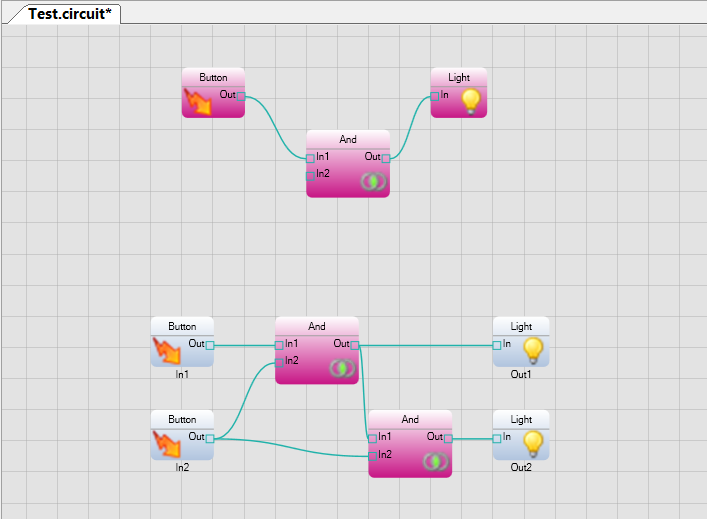
Here is the result using the above test code in CircuitEditor:

Hope that helps! Please let me know how it goes.


--Ron

Ron AtSony

unread,
Feb 12, 2015, 4:13:56 PM2/12/15
to vorp, authoring-to...@googlegroups.com

--
You received this message because you are subscribed to the Google Groups "Authoring Tools Framework" group.
To unsubscribe from this group and stop receiving emails from it, send an email to authoring-tools-fr...@googlegroups.com.
Visit this group at http://groups.google.com/group/authoring-tools-framework.
For more options, visit https://groups.google.com/d/optout.

vorp

unread,
Feb 13, 2015, 5:49:11 PM2/13/15
to authoring-to...@googlegroups.com
Excellent, Ron, thank you!
The first option works super easily. Implementing the next now.
Appreciate it!

-Len
On Wednesday, February 11, 2015 at 6:37:13 PM UTC-8, vorp wrote:
Reply all
Reply to author
Forward
0 new messages