Batch coregistering HiRISE *_RED.JP2/LBL files

mikita belikau
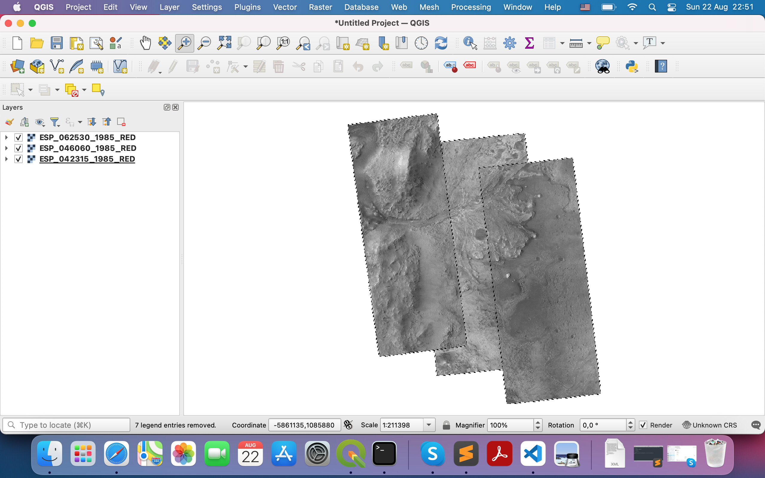
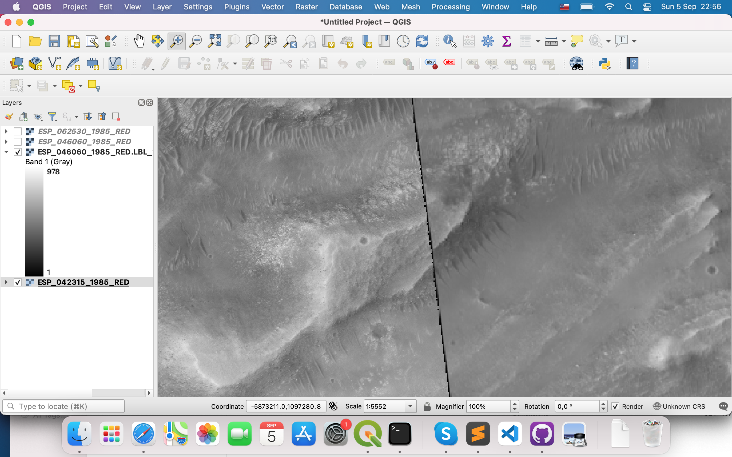
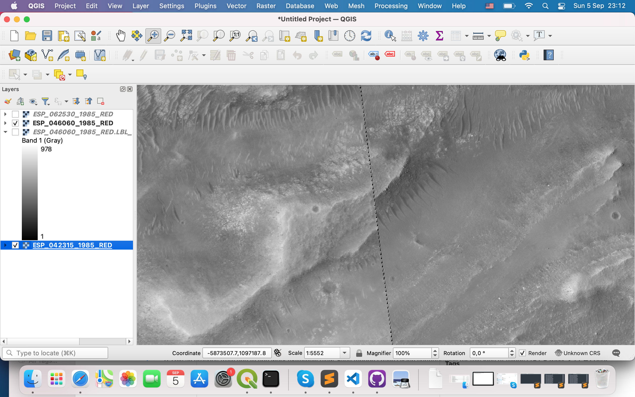
Here we see, that these 3 files have intersections
So what I did was:
- created cub file for each image with pds2isis
- called
ipfind ESP_042315_1985_RED.LBL.cub ESP_046060_1985_RED.LBL.cub ESP_062530_1985_RED.LBL.cub --normalize --debug-image 1 --ip-per-tile 50
Parameters and it’s values I took from im_feeling_lucky function of ASAP
Output was following
Finding interest points in “ESP_042315_1985_RED.LBL.cub”.
Read in nodata value: 0
Normalizing the input image…
Detected 52 raw keypoints!
Found 52 points.
Running sift descriptor generator.
Writing output file ESP_042315_1985_RED.LBL.vwip
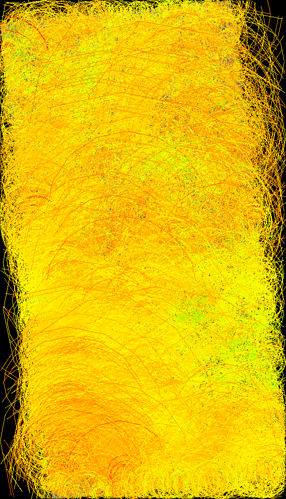
Writing debug image: ESP_042315_1985_RED.LBL_debug.png with downsample: 0.0164025
Finding interest points in “ESP_046060_1985_RED.LBL.cub”.
Read in nodata value: 0
Normalizing the input image…
Detected 41 raw keypoints!
Found 41 points.
Running sift descriptor generator.
Writing output file ESP_046060_1985_RED.LBL.vwip
Writing debug image: ESP_046060_1985_RED.LBL_debug.png with downsample: 0.0174001
Finding interest points in “ESP_062530_1985_RED.LBL.cub”.
Read in nodata value: 0
Normalizing the input image…
Detected 13 raw keypoints!
Found 13 points.
Running sift descriptor generator.
Writing output file ESP_062530_1985_RED.LBL.vwip
Writing debug image: ESP_062530_1985_RED.LBL_debug.png with downsample: 0.0177379
What worries me on this step is these debug images. They look like this:
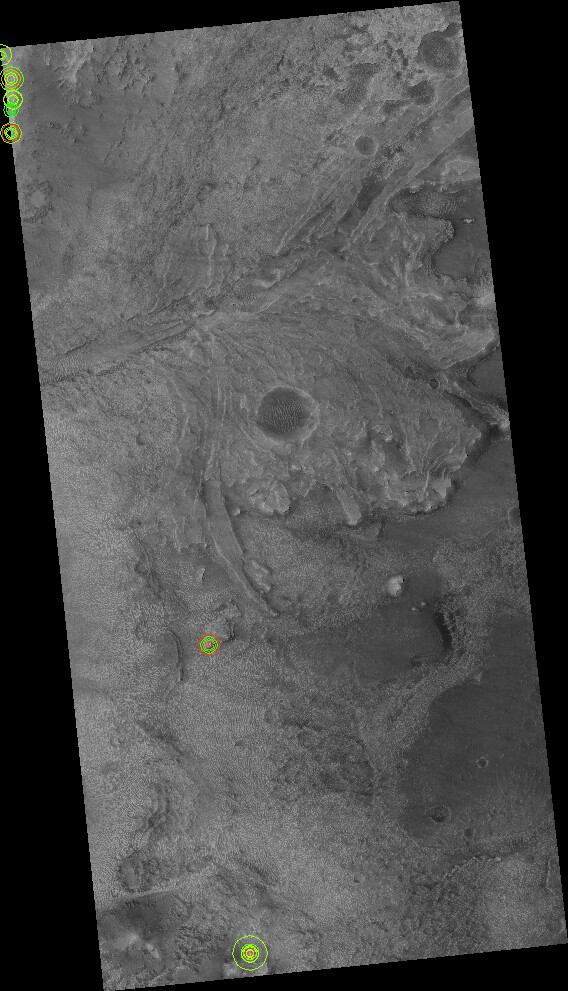
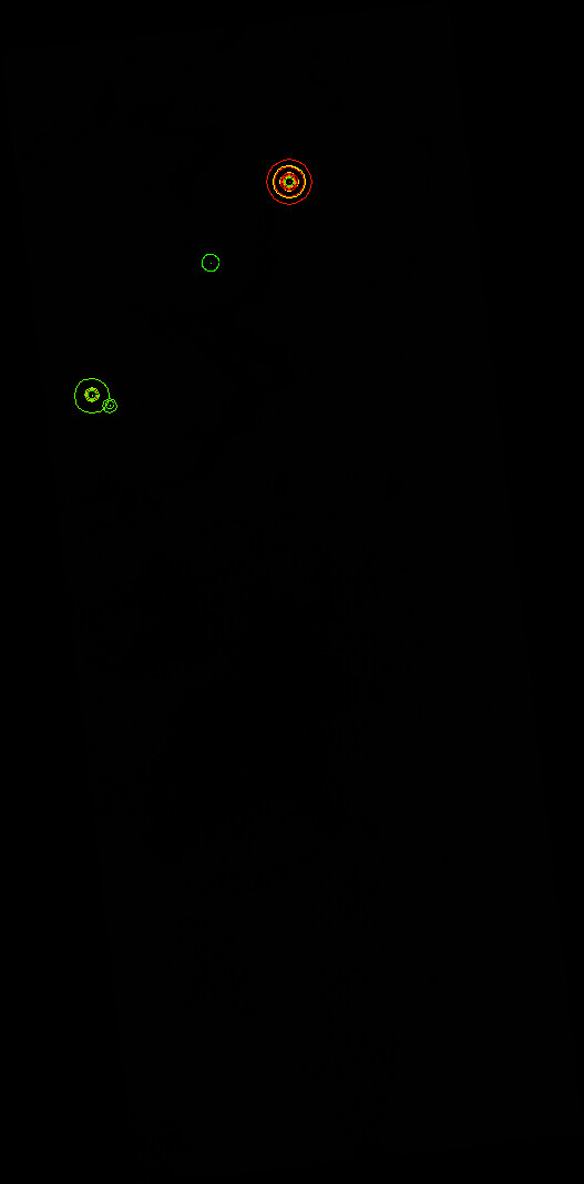
And
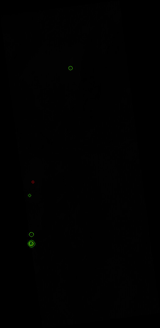
I believe this is the core problem of further failed step
I do not know what does this mean, but these 2 black images look like a bad sign for me
- called
ipmatch --debug-image --ransac-constraint homography ESP_042315_1985_RED.LBL.cub ESP_042315_1985_RED.LBL.vwip ESP_046060_1985_RED.LBL.cub ESP_046060_1985_RED.LBL.vwip ESP_062530_1985_RED.LBL.cub ESP_062530_1985_RED.LBL.vwip
Output was following
Matching between ESP_042315_1985_RED.LBL.cub (52 points) and ESP_046060_1985_RED.LBL.cub (41 points).
Using distance metric: L2
Matching:[****************************************************************] 100%Found 11 putative matches before duplicate removal.
Found 6 putative matches.
RANSAC Error. Number of requested inliers is less than min number of elements needed for fit. (3/4)
Attempting RANSAC with 2 of output inliers.
RANSAC Error. Number of requested inliers is less than min number of elements needed for fit. (2/4)
RANSAC Failed: RANSAC was unable to find a fit that matched the supplied data.
Matching between ESP_042315_1985_RED.LBL.cub (52 points) and ESP_062530_1985_RED.LBL.cub (13 points).
Using distance metric: L2
Matching:[****************************************************************] 100%Found 4 putative matches before duplicate removal.
Found 2 putative matches.
RANSAC Error. Not enough potential matches for this fitting functor. (2/4)
RANSAC Failed: RANSAC was unable to find a fit that matched the supplied data.
Matching between ESP_046060_1985_RED.LBL.cub (41 points) and ESP_062530_1985_RED.LBL.cub (13 points).
Using distance metric: L2
Matching:[***************************************************************.] 100%Found 4 putative matches before duplicate removal.
Found 3 putative matches.
RANSAC Error. Not enough potential matches for this fitting functor. (3/4)
RANSAC Failed: RANSAC was unable to find a fit that matched the supplied data.
So, it’s complaining on low number of detected common points.
How can I fix this?
In general, ASAP implemented the idea that was discussed here https://groups.google.com/g/ames-stereo-pipeline-support/c/NVrAIQy3Gv0. Also similar approach was described here https://github.com/NeoGeographyToolkit/StereoPipeline/issues/265
I suspect that my problem is that for some reason these cubes from RDR files are not good enough for ipfind.

Oleg Alexandrov
--
You received this message because you are subscribed to the Google Groups "Ames Stereo Pipeline Support" group.
To unsubscribe from this group and stop receiving emails from it, send an email to ames-stereo-pipeline...@googlegroups.com.
To view this discussion on the web visit https://groups.google.com/d/msgid/ames-stereo-pipeline-support/dc5d459b-4cf1-4318-9918-03a9a8a29e50n%40googlegroups.com.
mikita belikau
![Beyer, Ross A. (ARC-SST)[SETI INSTITUTE]'s profile photo](http://lh3.googleusercontent.com/a-/ALV-UjWIKbxTMrXKaPGUAugpuEhT_z4TBoNVn8x8OZbCW4yuj9IHcv0=s40-c)
Beyer, Ross A. (ARC-SST)[SETI INSTITUTE]
I’m hopeful that you’ll find a direct solution with the RDR data that you’re working with, but this isn't true:
> Why RDR and not EDR? Because for the area(s) I am interested there are no EDR
The RDR data are the “reduced” data records, and these are never released by HiRISE unless there are also the source “experimental” data records that have been released. Fundamentally, an RDR cannot exist without EDRs existing first.
For example, based on your screen shot, I can go to this URL:
https://hirise.lpl.arizona.edu/ESP_062530_1985
And scroll down to the “EDR Products” link: https://hirise-pds.lpl.arizona.edu/PDS/EDR/ESP/ORB_062500_062599/ESP_062530_1985/
Where I could download all of the EDRs that constitute this observation.
That being said, working with a derived RDR rather than attempting to assemble the EDRs yourself may be easier.
Ross
http://RossBeyer.net/science/
mikita belikau
mikita belikau
ipfind ESP_042315_1985_RED.LBL.cub ESP_046060_1985_RED.LBL.cub ESP_062530_1985_RED.LBL.cub --debug-image 1 --ip-per-tile 10 --per-tile-normalize --nodata-radius 3
Which gave me following outputFinding interest points in "ESP_042315_1985_RED.LBL.cub".
Read in nodata value: 0
Detected 16866 raw keypoints!
Found 16729 points.
Running sift descriptor generator.
Writing output file ESP_042315_1985_RED.LBL.vwip
Writing debug image: ESP_042315_1985_RED.LBL_debug.png with downsample: 0.0164025
Finding interest points in "ESP_046060_1985_RED.LBL.cub".
Read in nodata value: 0
Detected 14353 raw keypoints!
Found 14239 points.
Running sift descriptor generator.
Writing output file ESP_046060_1985_RED.LBL.vwip
Writing debug image: ESP_046060_1985_RED.LBL_debug.png with downsample: 0.0174001
Finding interest points in "ESP_062530_1985_RED.LBL.cub".
Read in nodata value: 0
Detected 12673 raw keypoints!
Found 12500 points.
Running sift descriptor generator.
Writing output file ESP_062530_1985_RED.LBL.vwip
Writing debug image: ESP_062530_1985_RED.LBL_debug.png with downsample: 0.0177379
Much better!
Now I have 16729, 14239, 12673 points. For now I set --ip-per-tile 10, so, maybe when I set it to 100-200 results will be even better. Need to check this.
So, now debug messages look like this
Matching between ESP_042315_1985_RED.LBL.cub (16729 points) and ESP_046060_1985_RED.LBL.cub (14239 points).
Using distance metric: L2
Matching:[***************************************************************.] 99%Found 436 putative matches before duplicate removal.
Found 368 putative matches.
RANSAC was unable to find a fit that matched the supplied data.
Attempting RANSAC with 122 of output inliers.
RANSAC was unable to find a fit that matched the supplied data.
Attempting RANSAC with 81 of output inliers.
--> Homography: Matrix3x3((0.998078,0.000185939,-16772.8)(-0.00265371,1.00605,-6403.56)(-6.47686e-08,8.11789e-08,1))
Found 103 final matches.
Writing match file: ESP_042315_1985_RED.LBL__ESP_046060_1985_RED.LBL.match
Writing debug image: ESP_042315_1985_RED.LBL__ESP_046060_1985_RED.LBL.tif
Writing Debug:[******************************************************] Complete!
Matching between ESP_042315_1985_RED.LBL.cub (16729 points) and ESP_062530_1985_RED.LBL.cub (12500 points).
Using distance metric: L2
Matching:[***************************************************************.] 99%Found 173 putative matches before duplicate removal.
Found 160 putative matches.
RANSAC was unable to find a fit that matched the supplied data.
Attempting RANSAC with 53 of output inliers.
RANSAC was unable to find a fit that matched the supplied data.
Attempting RANSAC with 35 of output inliers.
RANSAC was unable to find a fit that matched the supplied data.
Attempting RANSAC with 23 of output inliers.
RANSAC was unable to find a fit that matched the supplied data.
Attempting RANSAC with 15 of output inliers.
RANSAC was unable to find a fit that matched the supplied data.
Attempting RANSAC with 10 of output inliers.
RANSAC was unable to find a fit that matched the supplied data.
Attempting RANSAC with 6 of output inliers.
RANSAC was unable to find a fit that matched the supplied data.
Attempting RANSAC with 4 of output inliers.
--> Homography: Matrix3x3((-2.4393,0.182904,15666)(-2.86632,0.560033,11411.8)(-0.000150837,6.62159e-06,1))
Found 4 final matches.
Writing match file: ESP_042315_1985_RED.LBL__ESP_062530_1985_RED.LBL.match
Writing debug image: ESP_042315_1985_RED.LBL__ESP_062530_1985_RED.LBL.tif
Writing Debug:[******************************************************] Complete!
Matching between ESP_046060_1985_RED.LBL.cub (14239 points) and ESP_062530_1985_RED.LBL.cub (12500 points).
Using distance metric: L2
Matching:[***************************************************************.] 99%Found 125 putative matches before duplicate removal.
Found 114 putative matches.
RANSAC was unable to find a fit that matched the supplied data.
Attempting RANSAC with 38 of output inliers.
RANSAC was unable to find a fit that matched the supplied data.
Attempting RANSAC with 25 of output inliers.
RANSAC was unable to find a fit that matched the supplied data.
Attempting RANSAC with 16 of output inliers.
RANSAC was unable to find a fit that matched the supplied data.
Attempting RANSAC with 10 of output inliers.
RANSAC was unable to find a fit that matched the supplied data.
Attempting RANSAC with 6 of output inliers.
RANSAC was unable to find a fit that matched the supplied data.
Attempting RANSAC with 4 of output inliers.
--> Homography: Matrix3x3((-0.208809,0.00970083,10261.9)(1.35583,-0.409195,16893.1)(1.46242e-05,-1.89501e-05,1))
Found 4 final matches.
Writing match file: ESP_046060_1985_RED.LBL__ESP_062530_1985_RED.LBL.match
Writing debug image: ESP_046060_1985_RED.LBL__ESP_062530_1985_RED.LBL.tif
![Alexandrov, Oleg (ARC-TI)[KBR Wyle Services, LLC]'s profile photo](http://lh3.googleusercontent.com/a-/ALV-UjVGukhtKFgQS_9MOcmN5PVOvDbkaQxhwU5C3rzD5Hsp_7wxXA=s40-c)
Alexandrov, Oleg (ARC-TI)[KBR Wyle Services, LLC]
> Found 4 final matches.
mikita belikau
Oleg, again, thanks for your reply. Will try to follow your advices.
mikita belikau
mikita belikau
pc_align --num-iterations 0 --max-displacement 300 --match-file ESP_042315_1985_RED.LBL__ESP_062530_1985_RED.LBL.match ESP_042315_1985_RED.LBL.cub ESP_062530_1985_RED.LBL.cub --save-transformed-source-point -o aligning_result
Here I use cubes that were created for corespondent .LBL files.--> Setting number of processing threads to: 4
Writing log info to: aligning_result-log-pc_align-08-28-1342-38379.txt
Detected datum from ESP_042315_1985_RED.LBL.cub:
Geodetic Datum --> Name: D_Mars Spheroid: Mars_localRadius Semi-major axis: 3394839.8133163 Semi-minor axis: 3394839.8133163 Meridian: Reference_Meridian at 0 Proj4 Str: +proj=eqc +lat_ts=15 +lat_0=0 +lon_0=180 +x_0=0 +y_0=0 +a=3394839.8133163 +b=3394839.8133163 +units=m +no_defs
Will use datum (for CSV files): Geodetic Datum --> Name: D_Mars Spheroid: Mars_localRadius Semi-major axis: 3394839.8133163 Semi-minor axis: 3394839.8133163 Meridian: Reference_Meridian at 0 Proj4 Str: +proj=eqc +lat_ts=15 +lat_0=0 +lon_0=180 +x_0=0 +y_0=0 +a=3394839.8133163 +b=3394839.8133163 +units=m +no_defs
Reading match file: ESP_042315_1985_RED.LBL__ESP_062530_1985_RED.LBL.match
Transform computed from source to reference using a match file:
1.02429 -0.0359572 -0.0079876 104426
0.0359796 1.02432 0.00276293 -104659
0.00788572 -0.00304155 1.02492 -22769.4
0 0 0 1
Computing the intersection of the bounding boxes of the reference and source points using 9000000 sample points.
Reference box: (Origin: (77.2973, 18.325) width: 0.164487 height: 0.269035)
Source box: (Origin: (77.2273, 18.3453) width: 0.142319 height: 0.269579)
Intersection reference box: (Origin: (77.2973, 18.3421) width: 0.0741431 height: 0.252007)
Intersection source box: (Origin: (77.259, 18.3453) width: 0.110638 height: 0.245349)
Intersection of bounding boxes took 81.7773 [s]
Reading: ESP_042315_1985_RED.LBL.cub
--> [********************************************************] Complete!
Loaded points: 77158839
Loading the reference point cloud took 64.8074 [s]
Reading: ESP_062530_1985_RED.LBL.cub
--> [********************************************************] Complete!
Loaded points: 41173266
Loading the source point cloud took 50.6867 [s]
Data shifted internally by subtracting: Vector3(705612,3.14231e+06,1.0757e+06)
Loading reference as DEM.
Building the reference cloud tree.
Reference point cloud processing took 198.786 [s]
Filtering gross outliers
Filtering gross outliers took 933.751 [s]
Reducing number of source points to 100000
Number of errors: 100000
Input: error percentile of smallest errors (meters): 16%: 2.11771, 50%: 5.21519, 84%: 44.1612
Input: mean of smallest errors (meters): 25%: 1.80614, 50%: 2.80052, 75%: 4.98651, 100%: 31.7621
Initial error computation took 17.4019 [s]
Alignment took 0.001482 [s]
Number of errors: 100000
Output: error percentile of smallest errors (meters): 16%: 2.11771, 50%: 5.21519, 84%: 44.1612
Output: mean of smallest errors (meters): 25%: 1.80614, 50%: 2.80052, 75%: 4.98651, 100%: 31.7621
Final error computation took 6.60767 [s]
Alignment transform (origin is planet center):
1.02429 -0.0359572 -0.0079876 104426
0.0359796 1.02432 0.00276293 -104659
0.00788572 -0.00304155 1.02492 -22769.4
0 0 0 1
Centroid of source points (Cartesian, meters): Vector3(706355,3.14204e+06,1.0755e+06)
Centroid of source points (lat,lon,z): Vector3(18.4673,77.3301,458.807)
Translation vector (Cartesian, meters): Vector3(17.0689,144.854,47.2951)
Translation vector (North-East-Down, meters): Vector3(-1.09344,15.1181,-152.582)
Translation vector magnitude (meters): 153.333
Maximum displacement of points between the source cloud with any initial transform applied to it and the source cloud after alignment to the reference: 0 m
Translation vector (lat,lon,z): Vector3(-1.84511e-05,0.000268957,152.582)
Transform scale - 1 = 0.0249564
Euler angles (degrees): Vector3(-0.17003,-0.440822,2.01176)
Euler angles (North-East-Down, degrees): Vector3(2.05584,0.064431,-0.191486)
Axis of rotation and angle (degrees): Vector3(-0.0785498,-0.214807,0.973493) 2.06586
Writing: aligning_result-transform.txt
Writing: aligning_result-inverse-transform.txt
Writing: aligning_result-trans_source.tif
--> [********************************************************] Complete!
Writing: aligning_result-beg_errors.csv
Writing: aligning_result-end_errors.csv
Writing: aligning_result-iterationInfo.csv
Saving to disk took 1744.51 [s]
mikita belikau
Oleg Alexandrov
>pc_align --num-iterations 0 --max-displacement 300 --match-file ESP_042315_1985_RED.LBL__ESP_062530_1985_RED.LBL.match ESP_042315_1985_RED.LBL.cub ESP_062530_1985_RED.LBL.cub --save-transformed-source-point -o aligning_result
1) Why this outcome tif of pc_align is so big - 22GB?
2) Since my final goal is to have aligned JP2 (LBL) files, which I use as Input and as a first step convert to cubes, at the end I want to have aligned JP2 (LBL). And question is - how can I do this?
3) From what I see in other threads people also use point2dem for processing result of pc_align, but I am not sure I need this if pc_align already produces output file for me. I just need to find a way to make this file relatively small (e.g., convert it to .VRT) and then convert this to JP2 (LBL). How can I do this?
mikita belikau
Oleg, thanks for your reply.
mikita belikau
mikita belikau
Oleg Alexandrov
--
You received this message because you are subscribed to the Google Groups "Ames Stereo Pipeline Support" group.
To unsubscribe from this group and stop receiving emails from it, send an email to ames-stereo-pipeline...@googlegroups.com.
To view this discussion on the web visit https://groups.google.com/d/msgid/ames-stereo-pipeline-support/5ad17cb2-051a-4cb0-99c9-8f137b30b955n%40googlegroups.com.
mikita belikau
Oleg Alexandrov
mikita belikau
mikita belikau
Oleg Alexandrov
Can we somehow speedup the process? I know that for gdalwarp this is probably not possible currently, but what about ipfind and ipmatch?
What about GPU? Does ASP have possibility to use this to speed-up the process?
> And for one cub file it didn't manage to find points at all. What could be the problem here? It was able to find it when --ip-per-tile was equal to 250.
Oleg, BTW, if I tried to use --interest-operator obalog together with setting options per tile (do not remember exactly was it ip-per-tile, or per-tile-normalization), but it complained that this is not possible. So, either per tile, or interest operator could be used, but not both of them.
mikita belikau
Oleg Alexandrov
--
You received this message because you are subscribed to a topic in the Google Groups "Ames Stereo Pipeline Support" group.
To unsubscribe from this topic, visit https://groups.google.com/d/topic/ames-stereo-pipeline-support/H7TTyAUGya0/unsubscribe.
To unsubscribe from this group and all its topics, send an email to ames-stereo-pipeline...@googlegroups.com.
To view this discussion on the web visit https://groups.google.com/d/msgid/ames-stereo-pipeline-support/3a4a9db4-5a75-4e03-bda8-b1f4ebc3a530n%40googlegroups.com.
mikita belikau
Alexandrov, Oleg (ARC-TI)[KBR Wyle Services, LLC]
mikita belikau
mikita belikau
stereo ESP_062530_1985_RED.LBL.cub ESP_042315_1985_RED.LBL.cub results/run
I got thisWarning: Stereo file ./stereo.default could not be found. Will use default settings and command line options only.
[ 2021-Sep-07 23:18:27 ] : Stage 0 --> PREPROCESSING
--> Setting number of processing threads to: 4
Warning: Stereo file ./stereo.default could not be found. Will use default settings and command line options only.
Writing log info to: results/run-log-stereo_pprc-09-07-2318-2392.txt
Using session: isis.
Loading camera model: ESP_062530_1985_RED.LBL.cub
Using image files: ESP_062530_1985_RED.LBL.cub, ESP_042315_1985_RED.LBL.cub
Using "./stereo.default"
--> Computing statistics for left
left: [ lo:5 hi:980 m: 461.134 s: 150.99]
--> Adjusting hi and lo to -+2 sigmas around mean.
left changed: [ lo:159.155 hi:763.113]
--> Computing statistics for right
right: [ lo:6 hi:991 m: 550.123 s: 160.82]
--> Adjusting hi and lo to -+2 sigmas around mean.
right changed: [ lo:228.483 hi:871.763]
--> Normalizing globally to: [159.155 871.763]
Loading camera model: ESP_062530_1985_RED.LBL.cub
Error: **ERROR** Unable to initialize camera model in Camera Factory.
**ERROR** Unable to find PVL group [Instrument] in file [ESP_062530_1985_RED.LBL.cub].
Stereo step 0: Preprocessing failed
Does anybody know how to pass RDR files to stereo in a right way?
Alexandrov, Oleg (ARC-TI)[KBR Wyle Services, LLC]
Sent: Tuesday, September 7, 2021 2:25 PM
To: Ames Stereo Pipeline Support <ames-stereo-pi...@googlegroups.com>
Subject: Re: [EXTERNAL] Batch coregistering HiRISE *_RED.JP2/LBL files
To view this discussion on the web visit https://groups.google.com/d/msgid/ames-stereo-pipeline-support/c112c272-1770-44e0-9f66-cf6f3a2b11cen%40googlegroups.com.
mikita belikau
Beyer, Ross A. (ARC-SST)[SETI INSTITUTE]
Sadly, no. RDR products “are” maps. They cannot be “spiceinit”ed. They are the result of taking camera-geometry images, and projecting them onto a terrain model (in the case of HiRISE RDRs, a smoothed version of MOLA gridded data, but still). Once an image has been map-projected, it is quite difficult to “reverse” the process, and you are generally better off starting from the camera-geometry images and working forwards.
> On Sep 8, 2021, at 11:02 AM, mikita belikau <miki...@gmail.com> wrote:
>
> Right, and spiceinit also wants cubes from EDR (IMG) files that do not have mapprojected info. So, it is again forcing me to use EDR files (.IMG)
>
> I just thought is it possible somehow to remove this mapprojected info from these cubes I got from RDR (.LBL) files, so that spiceinit can handle them properly?
>
> On Wednesday, September 8, 2021 at 12:03:51 AM UTC+2 oleg.al...@nasa.gov wrote:
> That is bad luck. It looks as if cameras cannot be initialized. Normally spiceinit does that.
Ross
http://RossBeyer.net/science/
mikita belikau
mikita belikau
stereo ESP_042315_1985_RED.map.cub ESP_065985_1985_RED.map.cub results/output
Here it complains on
Warning: Stereo file ./stereo.default could not be found. Will use default settings and command line options only.
[ 2021-Sep-24 22:02:05 ] : Stage 0 --> PREPROCESSING
--> Setting number of processing threads to: 4
Warning: Stereo file ./stereo.default could not be found. Will use default settings and command line options only.
Writing log info to: results/output-log-stereo_pprc-09-24-2202-26060.txt
Using session: isis.
Loading camera model: ESP_042315_1985_RED.map.cub
Loading camera model: ESP_065985_1985_RED.map.cub
Using image files: ESP_042315_1985_RED.map.cub, ESP_065985_1985_RED.map.cub
Using "./stereo.default"
--> Computing statistics for left
left: [ lo:0.0969188 hi:0.199513 m: 0.145607 s: 0.0160078]
--> Adjusting hi and lo to -+2 sigmas around mean.
left changed: [ lo:0.113591 hi:0.177622]
--> Computing statistics for right
right: [ lo:0 hi:0.0908073 m: 0.00742464 s: 0.0179881]
--> Adjusting hi and lo to -+2 sigmas around mean.
right changed: [ lo:0 hi:0.0434009]
--> Normalizing globally to: [0 0.177622]
Loading camera model: ESP_065985_1985_RED.map.cub
Error: **ERROR** Unable to initialize camera model in Camera Factory.
**ERROR** Unable to find PVL group [Instrument] in file [ESP_065985_1985_RED.map.cub].
How can I check this PVL group in the cub? And how to fix if it is wrong?

Scott McMichael
Beyer, Ross A. (ARC-SST)[SETI INSTITUTE]
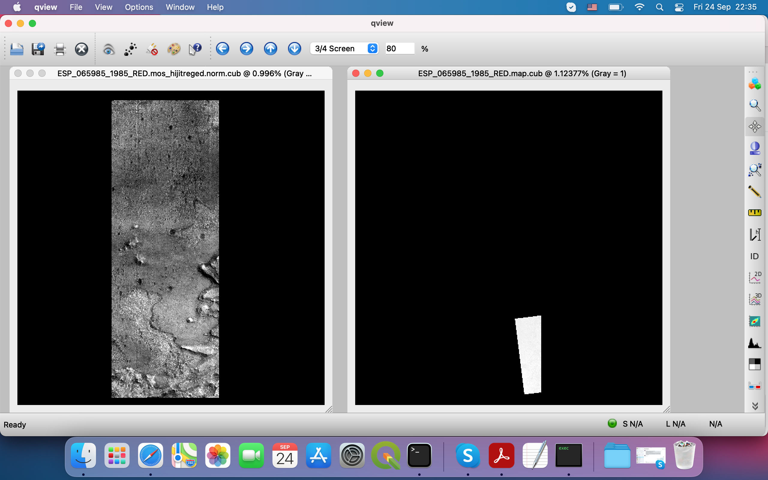
These two HiRISE observations, ESP_042315_1985 and ESP_065985_1985 are not a stereo pair, they do not appear to overlap.
When you give two HiRISE images to cam2map4stereo.py, that program extracts the lon/lat bounding boxes of the two images, and determines the intersection bounding box, and it then map-projects each of the images into that intersecting area, cropping off portions that are outside of that intersected box. These two images are close enough that an overlapping maxlon, minion, maxlat, minlat box can be computed, but the program doesn’t determine if the *actual* image footprints overlap, only that their bounding boxes do (and since MRO orbits aren’t exactly N/S, the footprints often appear “slanted” when projected).
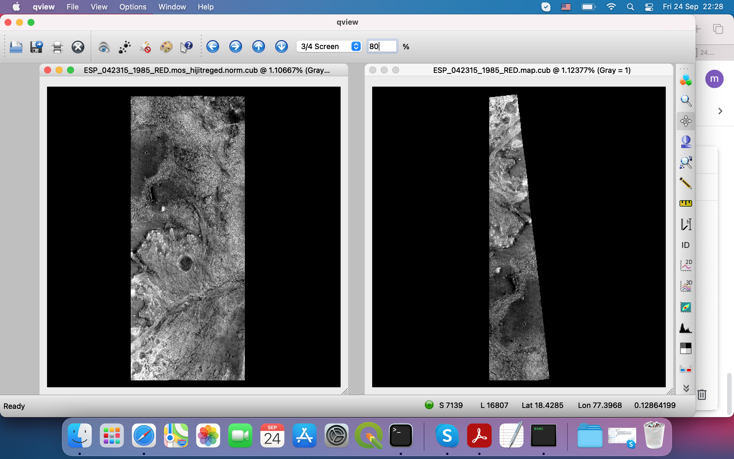
The maps on the right-hand side in both of your examples are the result of this. You can confirm this by looking at the scene in each of the left-hand images, and there aren’t any features that I can see in one image that are in the other. They appear to cover different portions of the floor of Jezero.
> Then I ran cam2map4stereo.py for the output from hiedr2mosaic.py which gave me image on the right - does not look Ok for me, cause even though orientation is Ok, but it is "cut off". Why is it like this?
>
> For another image I have this results of hiedr2mosaic.py (left) cam2map4stereo.py (right)
>
> <Screen Shot 2021-09-24 at 22.28.57.png><Screen Shot 2021-09-24 at 22.35.19.png>
Ross
http://RossBeyer.net/science/