Adding expansion bus to Altair-Duino 1.4 Standard
265 views
Skip to first unread message

John Meshelany Jr.
Oct 18, 2023, 9:47:31 PM10/18/23
to Altair-Duino
Hi, I am very new to the community, I just acquired a used Altair-Duino 1.4 Standard (From what I can tell from the PCB)
What would be involved in adding the expansion bus to this older model? Is there some sort of interposer board for the Due to wire in the DB-25 connector, or would I have to solder it manually?
Also, would I have to update the arduino sketch on the Due? Thanks!

Chris Davis
Oct 19, 2023, 10:03:11 AM10/19/23
to Altair-Duino
All of the info you need is here: https://github.com/dhansel/Altair8800-IOBus
Yes you need to solder it manually, and you will need to update the sketch on the Due.

Walt Perko
Oct 19, 2023, 11:39:52 AM10/19/23
to Altair-Duino
Hi,
+ 6-Slot IO Expansion Backplane
+ LED Display
+ 88-2SIO Serial
+ 88-PIO
+ 88-ACR
+ 88-C700
+ Speech Processor (includes the SP-0156-AL2 chip and speaks very well)
+ DAZZLER w/2x Joysticks
+ 4-Slot IO Expansion Backplane
I built this computer from the kits ... too bad it doesn't fit in the original box anymore;


I still have some blank boards for the expansion system and a fully loaded working system for sale. Whomever buys the entire computer system can have all the blank boards too. SPI / I2C boards, 88-2SIO boards, DS1302 boards, 88-DCDD boards, DAZZLER boards, DAZZLER JoyStick boards, VersaTerm boards, FabGL VT-100 boards.
This is an awesome setup and fully integrated for all sorts of activities: https://www.youtube.com/watch?v=BDaBaBL1mws&ab_channel=WaltPerko
I have too many Altair-Duino Pro computers and I need the space in my tiny apartment, so I'm selling this Altair-Duino Pro ... it's already boxed-up in heavy duty box ready for shipping ... or make an offer.
Altair-Duino Pro #1 $900 plus shiipping ...
+ 6-Slot IO Expansion Backplane
+ LED Display
+ 88-2SIO Serial
+ 88-PIO
+ 88-ACR
+ 88-C700
+ Speech Processor (includes the SP-0156-AL2 chip and speaks very well)
+ DAZZLER w/2x Joysticks
+ 4-Slot IO Expansion Backplane
I built this computer from the kits ... too bad it doesn't fit in the original box anymore;

Patrick Jackson
Oct 20, 2023, 8:08:07 PM10/20/23
to Altair-Duino
What regulator should we use on the expansion I/O board? A 7805?
Walt Perko
Oct 20, 2023, 8:27:30 PM10/20/23
to Altair-Duino
Hi,
The BOM has a "R-78E5.0-1.0"
I used a regular 1A LM7805 and attached a large piece of an aluminum soda can for a heat sink. That works too.
.
Patrick Jackson
Oct 20, 2023, 9:22:36 PM10/20/23
to Altair-Duino
Thanks! I got a few 7805s, guess I can do that
Chris Davis
Oct 21, 2023, 8:26:58 AM10/21/23
to Altair-Duino
I use a 7805. Just make sure you use the appropriate capacitors (0.33 uF for input and 0.1 uF for output).
Patrick Jackson
Jan 12, 2025, 9:29:11 PM1/12/25
to Altair-Duino
I have used a multimeter to make sure that my wires are where they should be, and they are. I just need to solder up the VIN pin correctly, thats the only one not making contact.
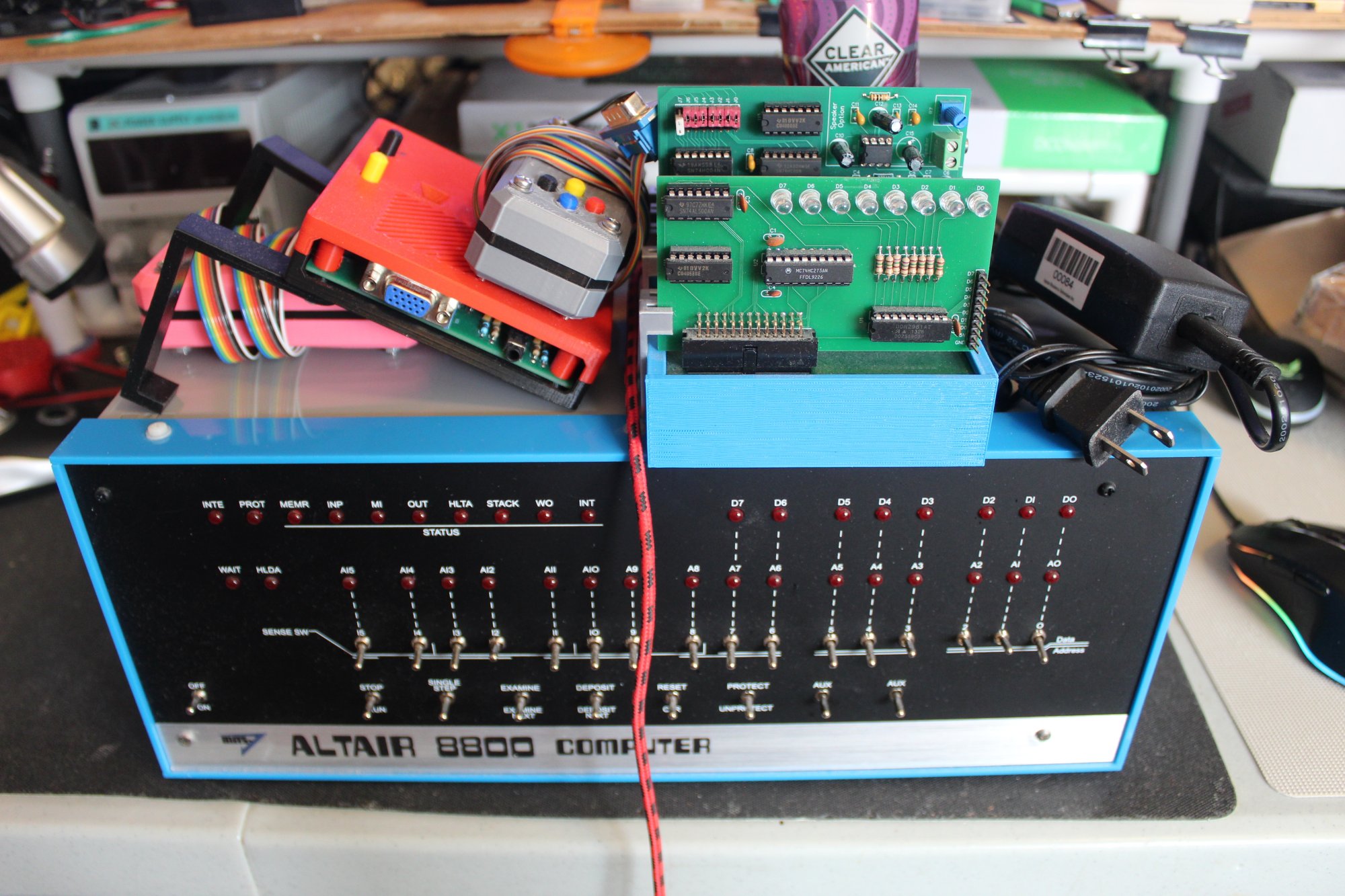
However, when I plug in the LED register board, I still get lockups and hot chips.
Am I using an incorrect DB25 cable? Is the schematic for the LED register card incorrect? I have no idea what is wrong
Am I using an incorrect DB25 cable? Is the schematic for the LED register card incorrect? I have no idea what is wrong

John Galt
Jan 13, 2025, 12:49:33 PM1/13/25
to Altair-Duino
with the I/O back plane for the DUE you can't use a continuity test for the wire verification all the wires are connected together so if you put one end of your meter on pin 1 then it will read continuity on all 24 pins regardless of position.
thus it is really easy to miss something and you think you got it right.
I used a numbered break out 25 pin connector with labels so i could do the wiring in groups then connect them to the correct pins on the connecter to try and avoid this confusion.
i posted a PDF to try and help people a few months ago.
i posted a PDF to try and help people a few months ago.
for the power voltages I taped off the front panel board on the right hand side. 3.3 and 5V, VIN, main ground. i worked in bundles to try and make sure i connected everything to the right place.
I ran rainbow wires in bundles for Data, Address, and Misc verified position on he DUE pcb and then ran each wire to the correct position on the labeled breakout board for the 25pin connection.
that was all trying to make sure i got everything in the right spot. it worked the first time so i did the same thing for the second Altair-duino.
I purchased 2 LED board from Chris i didn't use the version listed on the github from David that is a little different.
for my disk controller i also used Chris's version.
for the RTC and speech cards i used David's version and also David's version of the 4 position backplane.
Chris Davis
Jan 13, 2025, 2:18:19 PM1/13/25
to Altair-Duino
Did you source your own parts? Are you using 26-pin keyed female headers (with the "plugged" dual sockets on each end, or are you using unkeyed 26-pin connectors? That may seem insignificant, but I found out it's not.
Patrick Jackson
Jan 13, 2025, 5:40:47 PM1/13/25
to Altair-Duino
I have that exact backplane breakout board, and I have probed from the due to the pins on the db25 connector (male) that I have. Continuity works except for vin.
Chris Davis
Jan 13, 2025, 5:48:37 PM1/13/25
to Altair-Duino
I'm specifically asking about teh 26-pin female headers. Do you have the top one, or the bottom one?
Patrick Jackson
Jan 13, 2025, 11:23:05 PM1/13/25
to Altair-Duino
I have the top one
John Galt
Jan 14, 2025, 10:51:22 AM1/14/25
to Altair-Duino
that backplane breakout board is not very good... when i posted the PDF it was to show the pins used for each connection then solder directly to the DUE itself.
avoided lots of problems that way.
Patrick Jackson
Jan 14, 2025, 12:01:21 PM1/14/25
to Altair-Duino
Noted, I'll make some time this week to do a new connector with new fresh wires. I'll clean that burnt flux away XD.
I'm so jealous of all you guys with so many expansion cards! I also want to make my own XD
I'm so jealous of all you guys with so many expansion cards! I also want to make my own XD
John Galt
Jan 14, 2025, 4:13:05 PM1/14/25
to Altair-Duino
Just know i dreaded it. i spent weeks planning out how i was going to do it because it seemed really easy to make a mistake and then trying to figure out where i went wrong would waste more time.

when i made a post and that breakout board was posted i thought oh great that might be a solution, then i looked into that breakout board further and decided it would make things worse.
but the breakout board gave me the correct connections to trace to on the DUE pcb. so i put together a bunch of notes to follow and that all helped me plan things out better.
when i finally started to wire things i broke it up into 3 parts, Data, address, and the misc. connections. that was when i found out that a continuity tester was worthless since everything seems to connect together.the test it gave me was making sure i had good connection to the
25pin connecter breakout i used to help as it was numbered clearly for each pin.
took me the day over the weekend to complete the wiring.
i also made a bunch of 3d prints to clean up my altair pro case and have everything ready to mount when the wiring was completed.
everything worked on the first try.
a few months later i realized i needed to convert my second altair-duino for the Backplane because i wrote a text to speech converter in Mbasic so that the speech board was usable. i wrote some clock programs and time set programs for the RTC board.
i re-ordered all the parts i used for the first conversion and reused my notes again, when through the same dreaded process, when completed the second conversion worked correctly as well.
it is really easy to solder to the wrong pin i will tell you so having that PDF handy as i broke everything down into 3 sections helped me keep everything organized and using magnifying glasses also helped me double check my soldering for issues along with a final IPA scrub to get everything off that might cause a problem later.
since i received the new Altair reproduction case i may need to repeat everything again as i have use for an external I/O back plane connection.
for me the most useful i/o board is the RTC however it does not have under 1 second resolution which is really what i need however it makes for a great random number generator and all around tool for programs i write.
for me the most useful i/o board is the RTC however it does not have under 1 second resolution which is really what i need however it makes for a great random number generator and all around tool for programs i write.
the Disk controller is kind of hit and miss, you have to have all that extra desk space to have large disk drives just hanging out and the reliability is much less then just using the SD card.
it was a real pain trying to get 3 drives to work with each other hours of trying to align the head tracking between all of them. i had a 4th drive that just refused to work with the other 3 and i stuck it inside a PC instead.
it was a real pain trying to get 3 drives to work with each other hours of trying to align the head tracking between all of them. i had a 4th drive that just refused to work with the other 3 and i stuck it inside a PC instead.
i designed my own 3d printed cases for those drives.
the serial and parallel ports i don't need as i added an additional port to my original DUE PCB.
the LED board is useful for quick diagnostics and you can wire in relays to the GPIO pins and control external devices if you want.
the Speech board is amusing at least with the program i wrote. its easy to expand with the software i put together so you can easily add speech to your programs.
the other boards have no real purpose for me. i have no plans to feed in paper tape or cassette tape
thus the most interesting board is the Disk controllers since that will have some disk drives sitting proudly on your desk.
in the original configuration you can't really see the LED board,, that was why i designed a nice external housing.
Walt Perko
Jan 14, 2025, 4:26:28 PM1/14/25
to Altair-Duino
Hi,
+ 6-Slot IO Expansion Backplane
+ LED Display
+ 88-2SIO Serial
+ 88-PIO
+ 88-ACR
+ 88-C700
+ Speech Processor (includes the SP-0156-AL2 chip and speaks very well)
+ DAZZLER w/2x Joysticks
As a dyslexic ... this isn't an easy task, but I got it done so it's just a matter of taking your time, doing one wire at a time making sure to have the connection list and your DMM to check each connection before going onto the next to be sure you're getting the wires in the right places.
I've moved off the Altair-Duino and into real S-100 computers now so now this computer is in a box ready to go. I have posted a few videos in the forums here showing the system working different functions including speech and singing.
This is a collector's computer. This Altair-Duino Pro is the earlier design ... it's already boxed-up in heavy duty box ready for shipping ... make a reasonable offer.
Altair-Duino Pro and all the extras:
+ 6-Slot IO Expansion Backplane
+ 4-Slot IO Expansion Backplane
+ LED Display
+ 88-2SIO Serial
+ 88-PIO
+ 88-ACR
+ 88-C700
+ Speech Processor (includes the SP-0156-AL2 chip and speaks very well)
+ DAZZLER w/2x Joysticks
I built this computer from the kits ... too bad it doesn't fit in the original box anymore;
.
Reply all
Reply to author
Forward
0 new messages