Need help understand the stepper behavior or fix an issue I have with how to achieve continuous stepper movement
369 views
Skip to first unread message

Saleh Ramadan
Oct 5, 2018, 9:28:38 AM10/5/18
to accelstepper
Hello all,
I'm having the followign setup:
- NEMA17 stepper
- Arduino Nano
- TMC2100 driver
I also have the following setup between Arduino and the TMC2100 driver:
- Pin 11 on Arduino goes to ENA pin in TMC2100
- Pin 10 on Arduino goes to Step in TMC
- Pin 9 on Arduino goes to DIR on TMC
- GND and VIO on TMC go to Arduino 5v and GND pins
- GND and the VM pins on TMC goes to a 12v 2A DC power supply
I wanted to get 1/4 step so I connected CFG1 to Arduino's GND, and CFG2 to Arduino's 5V
The code I'm using in the sketch is this:
#include <AccelStepper.h>
// Define a stepper and the pins it will use
AccelStepper stepper(1, 10, 9);
void setup()
{
  Serial.begin(9600);
  // Change these to suit your stepper if you want
  stepper.setCurrentPosition(0);
  stepper.setMaxSpeed(800);
  stepper.setSpeed(100);
}
void loop()
{
  Serial.println("moved");
  Serial.println(stepper.currentPosition());
  stepper.runSpeed();
}
I'm expecting to get a continuous movement, however what I get is the stepper moves for one second, and stops for another.. I've been trying to understand the behavior or know what is going on without any success..
I'm looking to use this setup in an electric focuser modification for a telescope and I am only at the step of completing the stepper motor work to get to test it.
Appreciate your input!

gregor
Oct 5, 2018, 1:23:32 PM10/5/18
to accelstepper
Hi,
1) to use the enable pin with AccelStepper, you need to specify it. See setEnablePin() and setPinsInverted() in the Accelstepper documentation.
2) use Serial prints sparsely. It is slow and will limit stepper motor speed.
so you're saying that the stepper moves for one second (taking several steps, not just one), then stops for one second?

Richard Bogard
Oct 5, 2018, 1:51:19 PM10/5/18
to accels...@googlegroups.com
That behavior is consistent with a lost step. Once a step is lost force applied to the cam will not only not be in sync . It will be completely out of sync. no amount of current or strength of flux is going to correctly apply force in the correct direction to allow for the unit to make up for its lost step . There are two ways to solve this problem . when increasing the frequency , if you increase the frequency by a fundamental elemental frequency of the original frequency then the short period of time during acceleration where you have the highest likelihood of a lost step the new frequency will be harmonically in sync with the cam. during that moment you will have the maximum transfer of power from the magnetic field to the cam preventing the halting of the cam . Increasing the likelihood that the cams position is moving closer to the new frequency. Programatic frequency shifts have a fundamental flaw.... they are not continuous. They are quantum and suffer all the karma that comes with it. the higher your frequency the less likely you can select a fundamental frequency shift as the clock comparator comes closer to zero. it is better to look at your frequency shift on the clock comparator at zero to one and build upon that frequency shift pattern all the way down. not down to the slowest frequency of course, but the minimum starting frequency of the stepper motor. All of these formulas and all of these equations are force dependent. Force is acceleration. Any resistance will require additional force . Which will be a linear translation of acceleration . Using frequency shifts you simply apply more current in direct opposition. all the same. All your tests will be useless if there is no load on the system . And once you have achieved those answers they will not work for anything that requires more force than the force or resistance you used to model your tables
--
You received this message because you are subscribed to the Google Groups "accelstepper" group.
To unsubscribe from this group and stop receiving emails from it, send an email to accelstepper...@googlegroups.com.
For more options, visit https://groups.google.com/d/optout.
Richard Bogard
Oct 5, 2018, 1:56:52 PM10/5/18
to accels...@googlegroups.com
Oh my, I almost forgot option two. Use 64 steps per step . And use an external clock 10 times greater than the frequency you're trying to achieve . Then control that clock . That's option two
Saleh Ramadan
Oct 6, 2018, 7:59:40 AM10/6/18
to accelstepper
Hello!
Apologies for late reply.
Yes, it does move for several steps in that second, then stops, not just one step....
I believe it is something to do with the board itself (the TMC2100 driver board..). I bought these from eBay: https://www.ebay.com/itm/For-3D-Printer-TMC2130-TMC2100-Stepstick-Stepper-Motor-Driver-Module-Heat-Part/302748036708?ssPageName=STRK%3AMEBIDX%3AIT&var=601619597625&_trksid=p2057872.m2749.l2649
Not sure but I believe it is about how they are made and the quality?
I bought 4, for my luck, I picked the one that has issues in performance and now it ended up completely dead.
Then I used another one and movement of stepper was really smooth and great, so I'll put that step loss issue to the bad board..
Now I got 3 left, one of them has a serious overheating issues (even when I set the pot to 0.2 or 0.3v, and I connected it to 3.3v pins on arduino), so basically I ended with one I'm sure it is working fine, and one other I need to test..
I think next time I'll look for something branded with SilentStepStick logo or something to make sure it is not going to be of bad quality or not having quality check at all...
Saleh Ramadan
Oct 6, 2018, 8:05:59 AM10/6/18
to accelstepper
Also I wanted to ask, is there any way I can troubleshoot the overheating issue on that board?
I connected the board and pins according to this image:
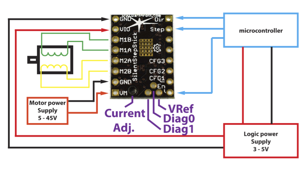
The motor power is coming form a 12V 2A adapter.. but will end up replacing that by either 8 or 10 rechargeable 1.2V batteries that have 2.4Ah capacity..
And CFG pins are going to Arduino's GND or 3.3V pins..
Appreciate your input!
Reply all
Reply to author
Forward
0 new messages