Lasindex, buffering & Lasgrid
206 views
Skip to first unread message

Peter Iver
Apr 29, 2022, 9:07:19 AM4/29/22
to LAStools - efficient tools for LiDAR processing
Hi Jochen,
hi all,
I'm trying to convert my laz files to TIF. I'm supplied mostly 1x1 km tiles, but at state borders, the files smaller. Now I have a problem with the buffering and the TIFs for incomplete laz files.
My Workflow is as follows:
> preparing a file list of laz files from different folders via cmd in windows
> lasindex
^
-lof file_list.txt
^
-cores 4
>
lasgrid
^
-lof file_list.txt
^
-cpu64
^
-cores 4
^
-mem 2000
^
-subcircle 0.2
^
-use_orig_bb
^
-buffered 2
^
-otif
^
-nclos
1000
^
-nrows 1000
^
-average
^
-odir XX
Now I got two issues:
1:
Since most of my laz files have 1mio points with 1000 rows and 1000 colums, I'd expect them to get some 8000 points from the buffer on top (buffered 2). Is that assumption right? In the command promt, I messages like these:
LASreaderBuffered: adding 6009 buffer points.
GeographicTypeGeokey: look-up for 4258 not implemented
GeogGeodeticDatumGeoKey: look-up for 6258 not implemented
GeographicTypeGeokey: look-up for 4258 not implemented
GeogGeodeticDatumGeoKey: look-up for 6258 not implemented
Can you shed some light on this? 6K points mean I get buffers on three sides, not four?
2:
Since my original laz points are on the lower left corner of every pixel I use nrows/ncols 1000 to fill also the last row and column. If I don't do that I always get an empty last column and row.
So far so good, the TIFs look alright for for inner-state tiles.
For files at state borders, which are typically not 1x1km, I get some issues with lasgrid. In the following example, I have a half filled laz file (~1kmx0.5km)
But here, in the final TIFs, the buffer points from outside are also rendered as pixels. I guess this is because lasgrid tries to reach 1000 rows/cols as I told it and I takes the buffer as well?
In my example I'd want my TIF to be rendered from row 0 to 1000 and col 500 to 1000.
How could I tackle that?
Example of a half filled file:
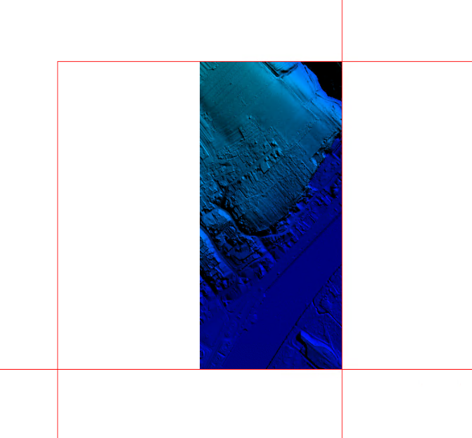
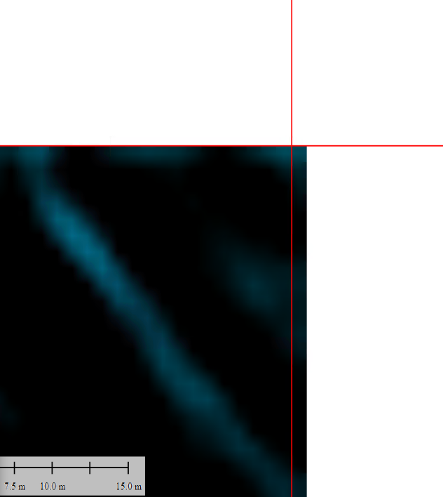
Zoom in on the upper left border:
Thx and kind regards
Peter

Jorge Delgado García
May 1, 2022, 2:26:37 PM5/1/22
to last...@googlegroups.com
Dear Peter,
Could you send me some examples in order to prepare the conversion? For example, a couple of half-size files and the complete adjacent files.
I don’t have a clear idea about your problem. Are your LAZ files according a grid or are irregular distributed points? If your files are according a grid the problem is very simple but you need to adjust your grid parameters (origin and spacing).
Jorge
--
Download LAStools at
https://rapidlasso.de
Manage your settings at
https://groups.google.com/g/lastools/membership
---
You received this message because you are subscribed to the Google Groups "LAStools - efficient tools for LiDAR processing" group.
To unsubscribe from this group and stop receiving emails from it, send an email to lastools+u...@googlegroups.com.
To view this discussion on the web visit https://groups.google.com/d/msgid/lastools/014464dd-c659-4c27-b7ac-8674bc91d032n%40googlegroups.com.

Peter Iver
May 2, 2022, 6:19:14 AM5/2/22
to LAStools - efficient tools for LiDAR processing
Dear Jorge,
thanks for your reply. Yes, my laz files are built in grids of regular
points.
Here are the files: https://drive.google.com/drive/folders/1pnfXdc7DIAEQNltCto0385XpeilL2XIJ?usp=sharing
Kind regards
Peter
thanks for your reply. Yes, my laz files are built in grids of regular
points.
Here are the files: https://drive.google.com/drive/folders/1pnfXdc7DIAEQNltCto0385XpeilL2XIJ?usp=sharing
Kind regards
Peter
Jorge Delgado García
May 2, 2022, 2:50:04 PM5/2/22
to last...@googlegroups.com
Thank you very much for sending the files, I already have a better idea of what the problem is and the data you have as a starting point.
The first thing you should keep in mind is that at the end your data is according to a mesh that has the points in the corners of the block (starting from the lower left corner and in blocks of 1000 x 1000 points -except in the blocks that are not complete-) but you need to estimate the height at the center of the block (pixel in GeoTIFF).
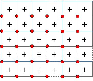
In red the LAZ points and black crosses the centers of the elements of your grid.
This is leading you to two effects that you must take into account:
1) You are applying in all cases an interpolation between the original LiDAR points, which in the case of the edges leads you to perform an extrapolation (by default it will use the -average option that would assign the average elevation between the closest points). As you are applying an interpolation anyway another option would be to use LAS2DEM and generate the model by interpolation and obtain the GeoTIFF directly (perhaps you can have some problems in the borders). If it is possible to obtain again the LAZ files displaced in the mesh 0.5m in x and y it would be good. From the original LAZ files using the LASthin option you can select the points closest to the mesh center.
2) In the outer part of the files you are causing an extrapolation that can cause a certain discontinuity in the different tiles. Better almost, merge all files into one file las2las -i *.laz -o merged.laz -olaz and this will smooth the discontinuity between the sheets. To define each of the files in your TIFF you can use in combination the options -ll xmin ymin -ncols 1000 -nrows 1000. If you use the definition of the lower left corner and the number of rows and columns you will have no problem.
If you have any additional questions, please feel free to contact me.
Jorge Delgado
--
Download LAStools at
https://rapidlasso.de
Manage your settings at
https://groups.google.com/g/lastools/membership
---
You received this message because you are subscribed to the Google Groups "LAStools - efficient tools for LiDAR processing" group.
To unsubscribe from this group and stop receiving emails from it, send an email to lastools+u...@googlegroups.com.
To view this discussion on the web visit https://groups.google.com/d/msgid/lastools/51a81f7f-8dd4-4f2b-8b27-2e473c3708b6n%40googlegroups.com.
Peter Iver
May 3, 2022, 5:27:16 AM5/3/22
to LAStools - efficient tools for LiDAR processing
Hey Jorge,
thanks for you reply. I'm glad that your understand my issue :)
Since the data is provided to my by a producer, I have to deal with te points starting at .0m.
Basically I imagined my workflow working like this:
- lasindex to help with on-the-fly buffering (working so far)
- use buffers to have no problems at the edges of my tiles, since I can use the buffer-points to interpolate the last row/column (working so far)
- use lasgrid to create TIFFs in a fast way (working only for 'complete' tiles)
For indexing and buffering, I looked at this workflow by Martin: https://rapidlasso.com/2015/08/07/use-buffers-when-processing-lidar-in-tiles/
So, no need to merge all tiles, because I buffer (='copy') just the points I need for the edge interpolation each time. Or am I missing something?
To run the interpolation in a reasonable way, I looked at this guide: https://rapidlasso.com/2020/01/13/converting-rasters-from-inefficient-ascii-xyz-to-more-compact-laz-or-tif-formats/
And this proposed code:
lasgrid -i temp\*.laz ^
-subsquare 0.25 ^
-step 1 -average ^
-use_tile_size 2000 ^
-odir dgm -olaz ^
-cores 4
As you can see in the TIFFs I uploaded, the interpolation works fine for the tiles that are complete.If I just merged everything and created a merged TIFF, can you please help me understand how your proposed code ( -ll xmin ymin -ncols 1000 -nrows 1000) would tackle the issue for slicing the tiles?
My complete (=normal) tiles start at .0 / .0 with 1000 rows and colums, but my incomplete files start at 500/0 or 0/500 or 0/200, etc and they differ from nrows1000 / ncols1000 in various individual ways.
I thought 'use_orig_bb' would force the incomplete tiles to only render pixels inside the bb, but I guess I overlook something there?
Thanks again!
Kind regards
Peter
Peter Iver
May 13, 2022, 3:01:51 AM5/13/22
to LAStools - efficient tools for LiDAR processing
To any future reader:
in the end, my solution is to use lastile and create the buffers there. I don't use on-the-fly-buffering anymore. Then, in lasgrid I create my TIFs. When comparing las2dem vs lasgrid, las2dem fails to fill the last line of a tile if there is no tile next to it. So I went with lasgrid, which is also faster.
Reply all
Reply to author
Forward
0 new messages