Mightyboard Rev E clones (Wanhao, CTC, FF) using CS connector as parallel power input
1,438 views
Skip to first unread message

Jetguy
Oct 17, 2014, 4:55:36 AM10/17/14
to 3dprintertips...@googlegroups.com
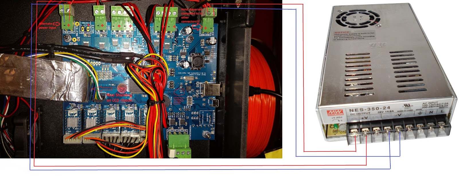
See diagram for using CS fan output instead as a parallel input from the main PSU for better power handling and less stress on the single power input connector.
PAY SPECIAL ATTENTION TO POLARITY HERE!!!

TRAMMALOT
Oct 17, 2014, 8:36:05 AM10/17/14
to 3dprintertips...@googlegroups.com
would the unpopulated "extra" next to it work also?
Jetguy
Oct 17, 2014, 8:39:05 AM10/17/14
to 3dprintertips...@googlegroups.com
No, because that is a switched output. CS is not switched.
Gregory Sullivan
Oct 17, 2014, 10:18:16 AM10/17/14
to 3dprintertips...@googlegroups.com
ok, I wonder if they make a 2 story connector? either for the board or for the 2 prong board connector itself?
--
You received this message because you are subscribed to a topic in the Google Groups "3D Printer Tips, Tricks and Reviews" group.
To unsubscribe from this topic, visit https://groups.google.com/d/topic/3dprintertipstricksreviews/XeAPyY2NmXw/unsubscribe.
To unsubscribe from this group and all its topics, send an email to 3dprintertipstricks...@googlegroups.com.
To post to this group, send email to 3dprintertips...@googlegroups.com.

Ryan Carlyle
Oct 17, 2014, 10:20:55 AM10/17/14
to 3dprintertips...@googlegroups.com
Using Extra as a power input would require pulling off the surface-mount nozzle fan FET (if your board has it) and putting a solder bridge from the FET source pad to drain pins. In other words, way too much trouble.
Ryan Carlyle
Oct 17, 2014, 10:22:00 AM10/17/14
to 3dprintertips...@googlegroups.com
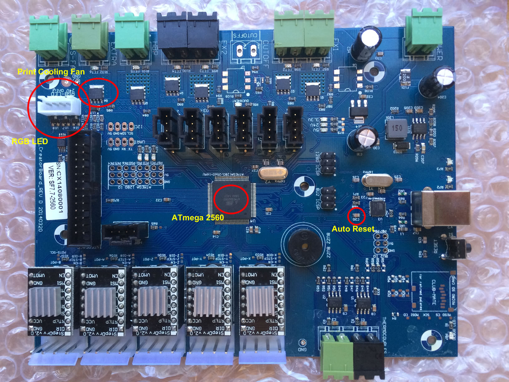
Hey Jetguy, in that diagram, what's the little red text near the USB plug?
Gregory Sullivan
Oct 17, 2014, 10:28:48 AM10/17/14
to 3dprintertips...@googlegroups.com
not really, i have a donor board with no fet....
thank you....
On Fri, Oct 17, 2014 at 10:22 AM, Ryan Carlyle <temp...@gmail.com> wrote:
Hey Jetguy, in that diagram, what's the little red text near the USB plug?
--
Jetguy
Oct 17, 2014, 10:40:05 AM10/17/14
to 3dprintertips...@googlegroups.com
FYI, that picture is from a Wanhao Duplicator 4S. I was pointing out the new features they did compared to the previous D4 and D4X.
It says, Auto Reset capacitor not installed. You must manually press reset to upload firmware.
Both my D4 and D4X came with C20 installed AKA auto reset.
That said, the D4 and D4X came without the "Extra" MOSFET soldered in (the resistors and LED are present on all boards) and connector was also not soldered.
Artem just bought a D4S based on my recommendation but then reported he didn't get one with the "EXTRA" FET installed? Not sure if his came with auto reset C20 either?


Artem
Oct 17, 2014, 11:24:37 AM10/17/14
to 3dprintertips...@googlegroups.com
My board says Rev A, I am missing the cooling mosfet and I didn't not have to press any reset buttons to upgrade to Sailfish. I think I have an "old" board. Hope they didn't take any other shortcuts with my bot...
On Friday, October 17, 2014 4:55:36 AM UTC-4, Jetguy wrote:
Jetguy
Oct 17, 2014, 11:32:13 AM10/17/14
to 3dprintertips...@googlegroups.com
There is no "difference" in the board, it's just if C20 is installed or if the MOSFET is soldered in.
Jetguy
Oct 17, 2014, 6:51:21 PM10/17/14
to 3dprintertips...@googlegroups.com
Let's be honest about the situation. Even on the other D4S board that had the FET, you still had to solder the connector. To solder the connector, you still have to remove the board from the machine and that disconnecting everything and going through that whole process.
The MOSFET is under $1 from Digikey, Mouser, or whoever your favorite supplier is, and you'd be buying a header connector and matching screw terminal plug at the same time anyway.
On the other hand, C20 is a very tiny, tiny component to solder. If you get that wrong, the board stops working because it's stuck in reset.
If you screw up the FET the most likely situation is solder shorting the gate to ground (solder bridging the pins). So that would blow the single output of the processor for that pin for that FET.
Everything else would work, you could still print, it would be no different than the day you got it and had no extra fan control. Again, I looked at the board and schematic The pins next to the gate are ground plane (AKA Drain). The tab is return from the external circuit (Source). I know people are scared to solder that but again, I'd say it's easier than a lot of jobs I've done and I don't even use SMT equipment to change out the 100 pin processor.
I'm just saying, that is the deeper analysis of the pros and cons of what parts they supplied. Sure I wish they all came with FETs, Connectors, and C20 installed. Maybe they are getting there and yours is just an example of the transition period during production. I hate having to press reset to upload firmware. Given the choice, I'd take auto reset from the factory, VS soldering in the FET and connector.
Artem
Oct 17, 2014, 7:05:46 PM10/17/14
to 3dprintertips...@googlegroups.com
No worries there, I'm running my fan directly from the PSU through a manual switch. That should work just fine for me for now.

Dan Newman
Oct 17, 2014, 8:07:58 PM10/17/14
to 3dprintertips...@googlegroups.com
> I'm just saying, that is the deeper analysis of the pros and cons of what
> parts they supplied. Sure I wish they all came with FETs, Connectors, and
> C20 installed. Maybe they are getting there and yours is just an example of
> the transition period during production. I hate having to press reset to
> upload firmware. Given the choice, I'd take auto reset from the factory, VS
> soldering in the FET and connector.
As I posted on the FlashForge group a week or two back, FF is at least now
> parts they supplied. Sure I wish they all came with FETs, Connectors, and
> C20 installed. Maybe they are getting there and yours is just an example of
> the transition period during production. I hate having to press reset to
> upload firmware. Given the choice, I'd take auto reset from the factory, VS
> soldering in the FET and connector.
supplying their version of the rev E board with
1. ATmega 2560 installed with correct bootloader + Sailfish 7.7
2. C20 installed and 8u2 with appropriate firmware
3. Extra FET + connector
4. RGB LED connector and electronics (but not the LED strip itself)
5. Like everyone else, correction to the 5V regulator fiasco
Dan
Artem
Oct 17, 2014, 8:26:00 PM10/17/14
to 3dprintertips...@googlegroups.com
I missed the 5V fiasco. What is that? Does it affect my bot?
On Friday, October 17, 2014 4:55:36 AM UTC-4, Jetguy wrote:
Dan Newman
Oct 17, 2014, 9:03:21 PM10/17/14
to 3dprintertips...@googlegroups.com
On 17/10/2014, 5:26 PM, Artem wrote:
> I missed the 5V fiasco. What is that? Does it affect my bot?
Search around in the old makerbot-operators group for self-destructing rev E mightyboards.
> I missed the 5V fiasco. What is that? Does it affect my bot?
Dan
Jetguy
Oct 17, 2014, 11:23:17 PM10/17/14
to 3dprintertips...@googlegroups.com
Artem, no, that's the main thing that Wanhao, and Flash Forge got right. They took Mightyboard rev E and fixed the power supply section compared to a MakerBot replicator dual.

TobyCWood
Oct 18, 2014, 5:38:20 PM10/18/14
to 3dprintertips...@googlegroups.com
That seems so long ago now...

y3ddet
Dec 14, 2015, 3:53:27 PM12/14/15
to 3D Printer Tips, Tricks and Reviews
Do you know if the FlashForge board is plug compatible with the LCD interface board on the Replicator 1? My mightyboard went belly up recently and I need to replace it, but I dont want to bother if this is going to be an extended exercise in ripping out components one at a time and replacing them with a different part.
Also - what are the mating terminal connectors for the FlashForge boards? Since this is a Replicator 1, it has the screwdown terminals and cable ends.
Dan Newman
Dec 14, 2015, 4:01:01 PM12/14/15
to 3dprintertips...@googlegroups.com
On 14/12/2015 12:53 PM, y3ddet wrote:
> Do you know if the FlashForge board is plug compatible with the LCD
> interface board on the Replicator 1? My mightyboard went belly up recently
> and I need to replace it, but I dont want to bother if this is going to be
> an extended exercise in ripping out components one at a time and replacing
> them with a different part.
The FlashForge mightyboard clone is plug compatible with a Replicator 1. It
> Do you know if the FlashForge board is plug compatible with the LCD
> interface board on the Replicator 1? My mightyboard went belly up recently
> and I need to replace it, but I dont want to bother if this is going to be
> an extended exercise in ripping out components one at a time and replacing
> them with a different part.
is not with a Rep 2 or 2X.
> Also - what are the mating terminal connectors for the FlashForge boards?
> Since this is a Replicator 1, it has the screwdown terminals and cable ends.
couple of years and I do not know offhand what connectors they are currently
using. (I always removed the terminals from the FF boards I received since, like
the MakerBot boards, they generally weren't correct for the currents involved.)
Dan
y3ddet
Dec 14, 2015, 4:03:56 PM12/14/15
to 3D Printer Tips, Tricks and Reviews
Thanks Dan.
It sounds like replacing the quick-disconnect terminals is the better option. Do you have a recommended screw down terminal part number that is know to have the right current rating?
Dan Newman
Dec 14, 2015, 4:23:17 PM12/14/15
to 3dprintertips...@googlegroups.com
On 14/12/2015 1:03 PM, y3ddet wrote:
> Thanks Dan.
>
> It sounds like replacing the quick-disconnect terminals is the better
> option. Do you have a recommended screw down terminal part number that is
> know to have the right current rating?
1. Forgot to mention, the power entry to the clone boards is different than the
> Thanks Dan.
>
> It sounds like replacing the quick-disconnect terminals is the better
> option. Do you have a recommended screw down terminal part number that is
> know to have the right current rating?
genuine Rep 1. You'll need to do something with the power cord from the PSU to
route the 2 x 24V and 2 x GND wires to the board. Since I don't use the MBI PSU,
I've never bothered attempting to do that. (The MBI PSU is underpowered but works.)
Most people making these sorts of mods remove the power entry terminals and solder
wire of the correct gauge directly to the board. They then connect those wires
directly to the PSU. But if you use the external MBI power brick, you will need
to do something different.
2. The HBP draws the most current. On a genuine Rep 1 it's about 6.3A @ 24V
(150W heater PCB). Increase that 20% for margin and you have 7.6A so go with
a terminal which, after derating, is good for at least 8A. Thus, you can get
by with a 10A terminal and do NOT tin the wire leads (nor use solid wire). Same doesn't hold
true for actual FlashForge bots which draw far more current on their heater beds.
Main issue in this regards with the genuine makerbot boards was the power switch
wasn't rated for the current and in some runs of the board, they used some spring
terminals which weren't correct for some of the currents involved.
Dan
y3ddet
Jan 14, 2016, 3:04:05 PM1/14/16
to 3D Printer Tips, Tricks and Reviews
Thanks for the pointers guys, I got my Wanhao board today and got it hooked in with a new Meanwell 24VDC brick instead of the MBot brick and it looks like power is fine. I was able to get the terminal/quick-disconnect plugs from the Wanhao storefront along with the electronics, so that part was relatively painless, but my firmware is all f-bar.
I used ReplicatorG to get the latest 7.7 sailfish installed and both the on-board firmware and RepG seem to think they are talking to the hardware, but I cannot get the X-Y steppers to do anything in response to an SD GPX file or commands from RepG. The main steppers seem to be ok because the X-Y moves at first, and the Z adjustment works fine (runs up to the stop, then closes to correct final distance as expected). Filament load/unload doesnt seem to drive the extruder steppers however.
I think the Wanhao EEPROM data must be bad and preventing the Replicator1 hardware from operating correctly - any docs that I should be looking at for the process to create EEPROM data from scratch or how to otherwise walk through a "zero-day" calibration of the machine (the home offsets and other data were on the blown and unusable RevE board).
I think the Wanhao EEPROM data must be bad and preventing the Replicator1 hardware from operating correctly - any docs that I should be looking at for the process to create EEPROM data from scratch or how to otherwise walk through a "zero-day" calibration of the machine (the home offsets and other data were on the blown and unusable RevE board).
Dan Newman
Jan 14, 2016, 4:46:05 PM1/14/16
to 3dprintertips...@googlegroups.com
On 14/01/2016 12:04 PM, y3ddet wrote:
> Thanks for the pointers guys, I got my Wanhao board today and got it hooked
> in with a new Meanwell 24VDC brick instead of the MBot brick and it looks
> like power is fine. I was able to get the terminal/quick-disconnect plugs
> from the Wanhao storefront along with the electronics, so that part was
> relatively painless, but my firmware is all f-bar.
>
> I used ReplicatorG to get the latest 7.7 sailfish installed and both the
> on-board firmware and RepG seem to think they are talking to the hardware,
> but I cannot get the X-Y steppers to do anything in response to an SD GPX
> file or commands from RepG. The main steppers seem to be ok because the X-Y
> moves at first, and the Z adjustment works fine (runs up to the stop, then
> closes to correct final distance as expected).
Did you use the stepper driver cards that came with the new board or did you
> Thanks for the pointers guys, I got my Wanhao board today and got it hooked
> in with a new Meanwell 24VDC brick instead of the MBot brick and it looks
> like power is fine. I was able to get the terminal/quick-disconnect plugs
> from the Wanhao storefront along with the electronics, so that part was
> relatively painless, but my firmware is all f-bar.
>
> I used ReplicatorG to get the latest 7.7 sailfish installed and both the
> on-board firmware and RepG seem to think they are talking to the hardware,
> but I cannot get the X-Y steppers to do anything in response to an SD GPX
> file or commands from RepG. The main steppers seem to be ok because the X-Y
> moves at first, and the Z adjustment works fine (runs up to the stop, then
> closes to correct final distance as expected).
use old ones? Some or all of the old ones may have died when the old main board
died.
Are the endstops connected and to the correct positions (Xmax, Ymax, Zmin)?
> Filament load/unload doesnt
> seem to drive the extruder steppers however.
it do that?
> I think the Wanhao EEPROM data must be bad and preventing the Replicator1
> hardware from operating correctly - any docs that I should be looking at
> for the process to create EEPROM data from scratch or how to otherwise walk
> through a "zero-day" calibration of the machine (the home offsets and other
> data were on the blown and unusable RevE board).
near the bottom, right corner of the Onboard Preferences window. The motherboard
must be powered on and connected to RepG via USB to do that. You can also do
this from the LCD UI: Utilities > EEPROM > Erase EEPROM,
http://www.sailfishfirmware.com/doc/ui-utilities-menu.html#x17-540003.7.18
Erasing it will then reset it from scratch.
Dan
Theodore Vaida
Jan 14, 2016, 4:57:49 PM1/14/16
to 3dprintertips...@googlegroups.com
> On Jan 14, 2016, at 2:46 PM, Dan Newman <dan.n...@mtbaldy.us> wrote:
>
> Did you use the stepper driver cards that came with the new board or did you
> use old ones? Some or all of the old ones may have died when the old main board
> died.
As for the extruder steppers, I did let the heater cores get up to 230 before trying to engage the extruder steppers, and I can manually force filament to extrude on both sides when the cores are hot, so it’s just a matter of getting the MightyBoard to drive the motors.
I’ll try the EEPROM wipe just to be sure there’s no stale junk left from the Wanhao official firmware.
Dan Newman
Jan 14, 2016, 5:24:09 PM1/14/16
to 3dprintertips...@googlegroups.com
On 14/01/2016 1:57 PM, Theodore Vaida wrote:
>
>> On Jan 14, 2016, at 2:46 PM, Dan Newman <dan.n...@mtbaldy.us> wrote:
>>
>> Did you use the stepper driver cards that came with the new board or did you
>> use old ones? Some or all of the old ones may have died when the old main board
>> died.
>
> The Wanhao came with all new stepper drivers which I left in place, as far as I can tell all of the connections are
> made the same as on the MBot original for the end stops. Since the X-Y gantry does move during the power-on and homing
> sequence, the board does seem to be able to drive them it just doesn’t want to do so when issued G codes.
For homing, an unaccelerated but slow motion command is issued within
>
>> On Jan 14, 2016, at 2:46 PM, Dan Newman <dan.n...@mtbaldy.us> wrote:
>>
>> Did you use the stepper driver cards that came with the new board or did you
>> use old ones? Some or all of the old ones may have died when the old main board
>> died.
>
> The Wanhao came with all new stepper drivers which I left in place, as far as I can tell all of the connections are
> made the same as on the MBot original for the end stops. Since the X-Y gantry does move during the power-on and homing
> sequence, the board does seem to be able to drive them it just doesn’t want to do so when issued G codes.
the firmware. Your actual X3G may be using accelerated motion commands
but if the EEPROM values of acceleration settings are bad/inapt then
it's hard to predict what might happen.
Also, it's possible that your gcode is setting stepper motor currents ("VREF" values). There
could be a problem with that occuring and faulty digital potentiometers on your board. (Keep
in mind, these Asian clone boards see no QA. It's when an Asian manufacturer puts them into
a printer they are assembling that QA/testing actually happens.)
> As for the extruder steppers, I did let the heater cores get up to 230 before trying to engage the extruder steppers,
> and I can manually force filament to extrude on both sides when the cores are hot, so it’s just a matter of getting
> the MightyBoard to drive the motors.
As to junk in the EEPROM, I've seen the Asian boards come with firmware loaded and absolute
random trash in the EEPROM. Bone fide Atmel AVRs come with the EEPROM all initialized to 0xFF
which firmwares then recognize as uninitialized EEPROM. But when the EEPROM is all arbitrary
values, that then necessitates doing an EEPROM reset. Moreover, when the bootloader and initial
firmware was loaded, it's possible to tell the ISP AVR programmer to wipe the EEPROM clean and
set it all back to 0xFF. My conclusion has been that some of these clone boards are coming with
non genuine Atmel parts or factory seconds or something that doesn't have the EEPROM all set
to 0xFF. AND, the Asian board fabs, when doing an initial firmware load, can't be bothered to
tell the programmer to first reset the EEPROM. Mind you, I do NOT know for a fact that your
EEPROM was loaded with arbitrary junk. I'm just mentioning what I've seen in the past with
some Asian clone boards from FlashForge and MBot3D.
Dan
y3ddet
Feb 3, 2016, 12:04:43 PM2/3/16
to 3D Printer Tips, Tricks and Reviews
Sorry this took so long for follow up, but wanted to confirm you were correct.
Resetting the EEPROM through the front panel menu worked, MB 1 Dual is now working 100% normally again with the FF/Wanhao controller board.
Reply all
Reply to author
Forward
0 new messages