Some worm gear thoughts
406 views
Skip to first unread message

Ryan Carlyle
May 18, 2018, 1:39:18 PM5/18/18
to 3DP Ideas
1) A worm wheel could be a decent extruder drive hob. Why do we not see more of this? Or why didn't we before cheap purpose-made pinch gears became available? (I haven't seen it much, anyway)
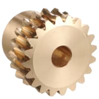
They tend to be fairly large diameter which means less force per motor torque (eg min 20mm pitch diameter compared to ~11mm pinch wheel) but that's easily addressed via motor gear ratio. For example, a planetary geared stepper could use a worm wheel directly as a drive hob.
2) If you find the right thickness / concave radius, I think you could mesh matching left-hand and right-hand worm wheels like helical spur gears, and the concave section would give enough room for filament, thus providing a dual-grip between-gears arrangement like the Printrbot Gearhead extruder. This could be very advantageous to use commercial off-the-shelf parts for cost and logistics...
3) If you drive a worm wheel with a worm gear as intended, and then the worm wheel is capable of directly acting as a drive hob, you can save parts count vs using a pinch gear + worm gearbox. This arrangement means one stepper rev advances the filament by distance equal to the gear modulus / tooth pitch. In practice, that's equivalent to about a 35:1 gearbox on a typical 11mm dia pinch gear (1mm filament travel per motor rev).
4) If you put worm wheels on opposite sides of a worm gear, they will counter-rotate. You can use those to drive pinch wheel shafts for a dual hob extruder with a high gearbox ratio and no special machined parts like a Bondtech. The challenge is getting the shafts close enough together for the pinch wheels to grip the filament... but if you use larger-diameter worm wheels as your pinch gears, then this could work. You'd use one worm gear, four worm wheels, shafts/bearings to make an extremely high power extruder. Probably end up costing about what a Bondtech costs though.

Whosawhatsis
May 19, 2018, 12:03:46 AM5/19/18
to Ryan Carlyle, 3DP Ideas
I remember speculating back when Nophead was posting about worm-driven extruders that you could use the worm wheel directly, and it would have the advantage that the worm would clean any ground filament out of the wheel's teeth. Don't think I've seen anyone do it, though. Of course, if you're driving the wheel from a worm, the diameter of the wheel doesn't matter, because you will have the same effective gear ratio as if you were using the worm as an old-school screw drive. A larger diameter wheel, though, would allow you to wrap the filament around the wheel with multiple idlers, and get HUGE amounts of contact area, so there's no way it would slip. You would, of course, need separate springs tensioning each idler, and thus focusing compression force in multiple places. Flattening the filament would be a concern, but a grooved idler would mitigate the issue. The bend in the filament would also help fight the filament's tendency to try to twist to avoid being pushed by the helical profile of the teeth (which, presumably, would be more helical than the typical profiles that are based on tap-hobbing).
--
You received this message because you are subscribed to the Google Groups "3DP Ideas" group.
To unsubscribe from this group and stop receiving emails from it, send an email to 3dp-ideas+...@googlegroups.com.
To post to this group, send email to 3dp-...@googlegroups.com.
To view this discussion on the web visit https://groups.google.com/d/msgid/3dp-ideas/4043be92-6308-4d7c-8a32-7f8e2a8d1c8a%40googlegroups.com.
For more options, visit https://groups.google.com/d/optout.
Ryan Carlyle
May 19, 2018, 9:23:55 PM5/19/18
to 3DP Ideas
Yeah, getting contact around more circumference on a 30mm+ diameter worm wheel is something I’m very interested in. But I’d probably do something more like an idle belt wrapped around the worm in a back-bend arrangement under high tension.

tray
May 20, 2018, 6:58:09 AM5/20/18
to 3DP Ideas
Directly driving filament from the worm gear of a worm drive might run into lubrication challenges.
Worm drives have mostly sliding contact as opposed to rolling contact, so proper lubrication is critical. Running filament over the gear would draw the lubricant out of the drive, meaning more maintenance. Also, worm drives tend to contaminate the lubricant with metal, which might be undesirable in some prints. OTOH, some people intentionally oil their filament, and if you pick the right oil, it could add to that popcorn-like bouquet some people smell from PLA.Ryan Carlyle
May 20, 2018, 11:51:43 AM5/20/18
to 3DP Ideas
That’s a really good point. I think it would need to be a plastic worm on brass so it could run dry.

ekaggrat singh kalsi
May 21, 2018, 4:38:27 AM5/21/18
to 3DP Ideas
a crazy bent filament drive.. i dont get it how the filament doesn't snap in this one!

Daren Schwenke
May 21, 2018, 6:52:54 PM5/21/18
to 3DP Ideas
Reminds me of the direct screw drive we saw a while back. I thought that was a good idea, just needs better execution.
They were losing a lot of drive force by not having a bearing or second drive opposite the filament drive. Perhaps driving two opposing screws at 12 and 6 o'clock via a third gear at 3 o'clock?
Drywall screws would work well. Nice clean/sharp edges, two pitch rates available, and hardened.
Ryan Carlyle
May 21, 2018, 8:45:09 PM5/21/18
to 3DP Ideas
I mean... RepRaps STARTED with direct screw drives. Check the BitsFromBytes Darwin extruder. They work. They just have some significant issues like dust generation and filament rotation. I’m not positive those are 100% solvable problems. My rollscrewder design kind of addressed dust (by rolling, not sliding/grinding) but the rotation issue is really hard to solve. Counter-rotating designs can’t entirely eliminate rotational slippage, due to momentary differences in friction as the threads bite with varying surface roughness or hit the same cut threads. The Stratasys inside thread drive patent uses a pretty small radius 90 degree curve in the filament feed path to limit rotation, but I don’t know how well that works.

Zatsit
May 22, 2018, 6:13:00 AM5/22/18
to 3dp-...@googlegroups.com
Do you mean something like that :


Then that :

And now that :

In all these versions, I replaced the hobbed gear by an elastomer strip, to remove any deformation of the filament, and simplify the mechanism by removing the usual spring. This works well, if the elastomer chosen has the right hardness and a suitable surface condition (rather sticky). Unfortunately, the TPU is not suitable (too smooth and slippery).
The main difficulties come from the fact that it is very difficult to machine correctly an elastomer with the right dimensions, which must be very precise. In addition, the elastic band is subject to a creep effect when compressed and rotating. It must therefore be mechanically fixed to the drive wheel, and not simply maintained by its elasticity.
In short, it works in a very encouraging way, but it is not easy to build a fully satisfactory prototype with this principle. I get enough extrusion force, but random slippages occur, because of the various imperfections of the prototype. I am convinced that it will be ideal when all this comes out of a mould, with an overmoulded gear wheel on a well chosen elastomer insert. This is my next Kickstarter project...
My latest prototypes use two crown pinions, driven by the same worm. Either way, it's the answer. This architecture can also be adapted to classic hobbed gears, with and external spring, which I am also currently trying.
This type of ultralight direct-drive extruder combines perfectly with the technical solutions I have already developed for my Zatsit delta printer, namely the gimballed motor in a "Flystruder" position, and the ultra-light water-cooled hot-end.
Toward the best ultra-light overall solution...
tray
May 22, 2018, 6:52:00 AM5/22/18
to 3DP Ideas
Well, linear slides get recirculating balls, how about some sort of recirculating interposers between the screw and the filament? That would solve the twist and filament dust issues. (By inserting another wear issue.) A cube isn't the right shape, but gets the idea across.
Ryan Carlyle
May 22, 2018, 3:28:39 PM5/22/18
to 3DP Ideas
Hmm, yes, that's very much like what I was imagining. Interesting approach. Is that a flex torsion shaft like a flex3drive or zesty nimble?
Zatsit
May 23, 2018, 7:06:10 PM5/23/18
to 3DP Ideas
Yes, direct-remote with a flexible shaft, since it is intended to a delta printer. In another context, it can be direct-drive.
Zatsit
Jun 12, 2018, 6:59:19 AM6/12/18
to 3DP Ideas
Here are my recent advances on this subject:

The extruder mechanism, with dual hobbed gear, and a single worm gear drive, is completely autonomous. It is mounted as a floating assembly, and is centered in place only in the presence of the filament.

On this prototype, all axes are mounted on ball bearings, but I don't get the impression that POM plain bearings on polished steel do less well.
The general principle is good. I will now try to simplify the construction, all in Hylite, and to lighten again.
32g for the whole, including the direct extrusion function, the cooled Hot-End function, and the support plate, it's already not so bad...


Patrick Barnes
Jun 12, 2018, 9:26:26 AM6/12/18
to Zatsit, 3DP Ideas
Wow! Impressive.
--
You received this message because you are subscribed to the Google Groups "3DP Ideas" group.
To unsubscribe from this group and stop receiving emails from it, send an email to 3dp-ideas+...@googlegroups.com.
To post to this group, send email to 3dp-...@googlegroups.com.
To view this discussion on the web visit https://groups.google.com/d/msgid/3dp-ideas/6bdb8b74-1cf1-46e4-b1d2-55c8e7a2b6c9%40googlegroups.com.

Asa DeBuck
Jun 23, 2018, 3:49:32 AM6/23/18
to 3DP Ideas
How much drive force are you getting on the filament? How well does the worm gear and gears on the dual hobbed hold up?
Patrick Barnes
Jun 23, 2018, 5:03:24 AM6/23/18
to Asa DeBuck, 3DP Ideas
I've seen feedback before regarding worm gear extruders along the lines of "oh but the retraction will be too slow!" If some minimum mm/s applies:
-Patrick
For a standard 1.8° drive stepper, what range of worm gear ratios (and step settings) do you think would be needed to still work well?
If a stepper is still too slow, (maybe there's some minimum workable spur gear tooth count?) are there faster drive options worth considering?
-Patrick
To view this discussion on the web visit https://groups.google.com/d/msgid/3dp-ideas/a2e822a7-251a-40ea-9676-970c409142de%40googlegroups.com.
Zatsit
Jun 23, 2018, 5:16:39 AM6/23/18
to 3DP Ideas
My systematic trials are ongoing.
I use an agile stepper motor (low inertia and low impedance), but small, and low torque. With this stepper, and a 0.4mm nozzle, I extrude up to about 15mm3/s of PLA at 215°C.
The POM gears creaked a little under load at first, but proper lubrication eliminated the problem.
The printing quality is excellent, because the stepper, very fast, does not limit my possibilities of pressure advance and retraction adjustment. It seems to me that the ringing increases a little, but it hardly remains perceptible.
The difference compared to a Titan extruder in flystruder position is not huge (better extrusion control, but a bit more ringing), but with this direct/remote solution, you can print TPU, without restriction!
Zatsit
Jun 23, 2018, 5:35:29 AM6/23/18
to 3DP Ideas
P.S. The E-Steps/mm is 1850.
Remember that with a worm screw system like this, the filament feed depends only on the worm pitch. In a way that is not intuitively obvious, the diameter of the drive wheels does not play in the gear ratio.
tray
Jun 24, 2018, 12:00:28 PM6/24/18
to 3DP Ideas
>My rollscrewder design
Not often I get zero hits on google. (other than back to this subject.) Do you have a link to your rollscrewder?
Ryan Carlyle
Jun 25, 2018, 3:57:17 PM6/25/18
to 3DP Ideas
Zatsit
Jul 25, 2018, 1:49:53 PM7/25/18
to 3DP Ideas
Here is my new compact print head, based on a worm gear driving two crown pinions.

This one weighs only 29g, in its version intended for Zatsit, and it is more precise and more robust than the previous one.

Above all, a key point of the architecture used makes it possible to envisage a version with four independent channels, but with only one drive motor, and a remote RC servo to choose the active channel. The change from one hot-end to the other should take about 1/3 of a second, depending on the performance of the RC servo used. I hope to keep the total weight around 40g, using smaller crowns.
A delta with 4 materials, without losing the performance of deltas, can you imagine?
Ryan Carlyle
Jul 27, 2018, 9:22:30 AM7/27/18
to 3DP Ideas
Like it :-)
Did you use the crown pinions to fit four drives from the start, or some other alignment reason?
Zatsit
Jul 28, 2018, 4:43:56 AM7/28/18
to 3DP Ideas
I've been trying to do mechanical multiplexing for a long time, and the possibility of doing it directly at the level of the crown pinions appeared to me when I developed this version.
Daren Schwenke
Jul 29, 2018, 4:30:13 AM7/29/18
to 3DP Ideas
Looking forward to seeing it. I too have dreamed of mechanical multiplexing, but never sorted it. :)
tray
Feb 17, 2019, 7:37:53 PM2/17/19
to 3DP Ideas
Anyone seen further developments on worm gear drive?
Zatsit
Feb 19, 2019, 4:42:42 AM2/19/19
to 3DP Ideas
I will soon release my two-way extrusion effector, with a single remote motor, for Zatsit. The principle is well tested, it is the manufacturing methods that pose the most problems.
tray
Feb 19, 2019, 8:01:44 PM2/19/19
to 3DP Ideas
With a worm drive, a NEMA 8 might suffice for torque, which would allow direct mounting, or nearly so. Not sure - worm drive is less efficient.
Reply all
Reply to author
Forward
0 new messages