Motion Mechanism Round-up

1,640 views
Skip to first unread message

Ryan Carlyle

unread,
Jun 29, 2014, 6:29:06 PM6/29/14
to 3dp-...@googlegroups.com
List of motion mechanisms in use in 3d printers. Not intended to be comprehensive -- just to show examples of types. Post additions/corrections and I will update. Correction posts will be periodically deleted to keep the thread clean.

Reprap YZ gantry / X plate or XZ gantry / Y plate
  • Mendel
  • Prusa
  • Printrbot Simple / Go / Plus
  • SmartRap

Cartesian XY gantry / Z plate
  • Darwin
  • Replicator 1 single/dual
  • Replicator 2/2x
  • FF Creator line
  • Duplicator 4 / 4x
  • Tons of clones and knock-offs

H-Bot diagonal XY gantry / Z plate
  • Replicator 5th gen
  • Replicator Mini
  • Replicator Z18
CoreXY diagonal gantry / Z plate
CoreXZ diagonal gantry / Y plate
  • Nicholas Seward's CoreXZ

Ultimaker XY gantry / Z plate
  • Ultimaker 1/2
  • Wanhao D5
  • Airwolf HD / HDx
  • RingRap
  • QuadRap
Column Delta three-axis parallel mechanism
  • Kossel 
  • Rostock
  • Wolfstock
  • Griffen
  • Tons of custom builds
Clavel style Rotary Delta
  • FirePick by Tin Whiskers
  • RappiDelta

"Simpson" style tripod (called "grounded Deltas" by Nick)
  • Nicholas Seward's GUS, THOR, LISA

Biglide XY parallel mechanism
  • RepRap Tuga (Scott-Russel linkage)

Other XYZ parallel mechanisms
  • Tripteron parallel cartesian mechanism (and quadrupteron, sextuperon)
  • Orthoglide

SCARA
  • Various standard SCARA printers (often combined pick-and-place bots)
  • Two-arm "parallel" SCARA like the RepRap Morgan

Cylindrical Polar 
  • R/theta/Z Polar 3D
  • Theta/Theta/Z "Bipolar" printer (build plate rotates, extruder on Z and theta)
Inverted SCARA / Polar
  • Polarworks Alta (build plate on Theta/Theta mechanism, extruder on Z)

Spherical Polar
  • ? (man, I want to build one now...)

Dual-Wire XY gantry / Z plate

UltiCore diagonal gantry / Z plate
  • Experimental -- Ultimaker style gantry utilizing CoreXY style motion mechanics

CoreXYZ three-axis gantry
  • Experimental -- 3D variant of CoreXY, with the entire gantry moving up/down as the Z stage

CoreXYAB diagonal gantry
  • Experimental -- uses differential motion to "multiplex" the extruder drive into the CoreXY motion drive

CoreXYZZY three-axis gantry
  • Experimental -- CoreXYZ variant designed to be tilted over on its side to change build area orientation

Galvo SLA
  • Form 1
DLP SLA
  • B9 Creator

    Message has been deleted
    Message has been deleted
    Message has been deleted
    Message has been deleted
    Message has been deleted
    Message has been deleted
    Message has been deleted
    Message has been deleted
    Message has been deleted

    Ryan Carlyle

    unread,
    May 22, 2015, 4:13:13 PM5/22/15
    to 3dp-...@googlegroups.com, temp...@gmail.com
    So... what do we call the 3DP1000 and Printrbot Pro mechanisms? They're pretty much just bog-standard XYZ serial Cartesian, right? It's not X-Y-Z or Y-X-Z serial like a typical CNC mill. Y-Z-X serial I think? 

    whosawhatsis

    unread,
    May 22, 2015, 7:10:07 PM5/22/15
    to Ryan Carlyle, 3dp-...@googlegroups.com
    Yeah, Y carries Z, which carries X, which carries E, platform is stationary (I like to make the distinction between the same mechanism moving the tool vs moving the platform).

    On Friday, May 22, 2015 at 13:13, Ryan Carlyle wrote:

    So... what do we call the 3DP1000 and Printrbot Pro mechanisms? They're pretty much just bog-standard XYZ serial Cartesian, right? It's not X-Y-Z or Y-X-Z serial like a typical CNC mill. Y-Z-X serial I think? 

    --
    You received this message because you are subscribed to the Google Groups "3DP Ideas" group.
    To unsubscribe from this group and stop receiving emails from it, send an email to 3dp-ideas+...@googlegroups.com.
    To post to this group, send email to 3dp-...@googlegroups.com.
    To view this discussion on the web visit https://groups.google.com/d/msgid/3dp-ideas/0c78efea-1199-4349-8024-058425ea9ba6%40googlegroups.com.
    For more options, visit https://groups.google.com/d/optout.

    Ryan Carlyle

    unread,
    Jul 10, 2015, 2:46:04 PM7/10/15
    to 3dp-...@googlegroups.com, whosaw...@gmail.com
    Naming conventions for 3D printer architectures are scattered all over the place. From the ISO standards for CNC mills:
    • Order of adjacent letters indicates order of serial stages, starting from the ground/frame
    • Something I'm adding: commas separate independent motion stages 
    • Apostrophes indicate moving build plate, lack of apostrophe means moving nozzle/tool
    • CNC mills define X as the longest linear axis, but for 3D printing it is more typical to define X as the left/right motion axis
    • CNC mills define Z as the axis of rotation of the spindle, which for us is the longitudinal axis of the extruder
    A Replicator 1 is a YX,Z' mechanism. A Mendel/Prusa style RepRap is a ZX,Y' mechanism. 

    From academic parallel robotics terminology:
    • Symmetrical parallel mechanisms can be prefixed with #- to indicate number of identical kinematic chains / arms
    • Type of arm can be described by a series of joint linkages (combining Pa for parallelogram, R for revolute, S for spherical, U for universal/cardan, P for prismatic/linear), starting from the frame side 
    • Actuated joints are underlined, passive joints are not
    • Something I'm adding: sub-linkages can be described within parentheses
    A Stewart-Gough hexapod is a 6-UPS mechanism. A column delta is typically considered a 3-PRPaR mechanism -- treating each arm parallelogram as one linkage. But it could also be broken down to the individual rods as 3-P(2-SS) for ball joints or 3-P(2-UU) for U-joints. The parallelogram notation is standard. 

    So that all works fine for typical Cartesian bots and typical parallel bots. But stuff gets weird when you talk about hybrids of parallel and serial construction. I have not found an established naming convention. For example, RepRap Morgan and Wally use parallel (two-arm) SCARA for the XY stage and a traditional linear Z stage. The XY stage is properly described with parallel terminology. Wally is 2-RR (actuated at the elbows) and Morgan is 2-RR (actuated at the shoulders).

    Hbot and CoreXY are also hybrids, but because they're goofy cable/belt-drives instead of classic kinematic chain / arm mechanisms, they kind of defy traditional classification. The parallel stage could be called a PP gantry. It's tricky because the gantry kinematic chains and DOFs (Y stage and X bridge) do not correspond to the the actuators (A and B diagonal motors). As far as I can tell, this isn't something that happens in the traditional serial/parallel robot control literature. 

    whosawhatsis

    unread,
    Jul 10, 2015, 2:54:03 PM7/10/15
    to Ryan Carlyle, 3dp-...@googlegroups.com
    Maybe use something like X/Y or X+Y to denote two axes that share actuators? That still doesn't cover my rhombic idea though. You might need something like (X+Y)/(Y+X) for hbot/corexy, which would allow you to use Y/(X+Y) for the rhombic thing?
    --
    You received this message because you are subscribed to the Google Groups "3DP Ideas" group.
    To unsubscribe from this group and stop receiving emails from it, send an email to 3dp-ideas+...@googlegroups.com.
    To post to this group, send email to 3dp-...@googlegroups.com.

    Ryan Carlyle

    unread,
    Jul 10, 2015, 3:03:01 PM7/10/15
    to 3dp-...@googlegroups.com, whosaw...@gmail.com
    Hmm, the rhombic drive makes things even trickier... but I'm not sure I'm convinced that it necessarily needs an independent description, from a kinematics standpoint. For example, CoreXY and HBot are mechanically different but have identical kinematics and I would say should share one "classification" when we're simply discussing kinematics. Similar to how a ball screw and a belt/pulley system get the same kinematic classification.

    While writing some book material that I later cut, I came up with a way of describing CoreXY and HBot type "parallel actuator over serial gantry" machines. Here's what I was thinking:

    Many popular 3D printing mechanisms are difficult to define using the above system, due to the use of parallel looped cable/belt drives. Traditional parallel cable-drive robots use a system of unidirectional free-hanging cables (treated as one-way-actuated SPS kinematic chains) that are spooled/unspooled on drums to pull on the end-effector. The most popular example today is the SkyCam system used to provide a bird's-eye view of sporting events.


    [picture of Skycam]


    Unlike traditional cable-driven robots, 3D printers often use closed loops to provide bi-directional motion from a single cable or belt. When a cable loop is arranged on a single axis, it is functionally equivalent to a prismatic joint actuated by a leadscrew or hydraulic cylinder. For example, the Replicator Cartesian gantry uses a series prismatic PP arrangement of cable-drive actuators for the X and Y axes, and a separate P leadscrew-drive actuator for the Z axis.


    [diagram of replicator cartesian prismatic cable actuators]


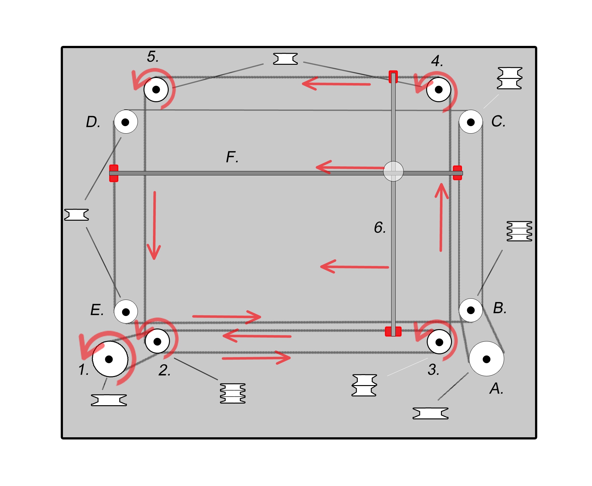
    But parallel looped cable-drive schemes are also possible. These are quite uncommon in general robot control applications and have not been discussed much in the academic literature. For example, the H-Bot and CoreXY gantries utilize loops of belts/cables to move a Cartesian gantry along actuator axes that do not correspond with the gantry axes. This arrangement is unique in that the prismatic cable-drive actuator motion is split amongst two (or more) prismatic joints in the mechanism.


    [diagram of H-bot and CoreXY prismatic cable actuators]

    [diagram of H-bot and CoreXY serial gantry links]


    This sort of hybrid serial/parallel arrangement is relatively novel in the field of robot control, but is very advantageous for 3D printing due to the low moving mass, simple control, and favorable precision:cost ratio. In this text, it will be described using a new nomenclature to show that the actuator axis is split between two (or more) mechanism joints. The representation P[j,i,...] will be used to show that the prismatic actuator's motion is split between other joints. Some function then relates the motions of the joints, such as P=Pj+Pi so that the total prismatic actuator travel is equal to the sums of the prismatic j joint travel and prismatic i joint travel. So a CoreXY gantry may be called a 2-P[PP] mechanism, to show that each prismatic actuator has its travel split between the two serial Cartesian gantry axes.


    Some examples of common 3D printing mechanisms described with this nomenclature:

    • Replicator or RepRap Cartesian gantry with independent build table: PP,P

    • Three-axis serial CNC mill gantry: PPP

    • Column Delta: 3-PRPaR

    • H-Bot, CoreXY, UltiCore: 2-P[PP]

    • CoreXYZ: 4-P[PPP]

    • Tripteron: 3-PRRR


    Some examples of robots not generally used for 3D printing:

    • Stewart-Gough hexapod: 6-UPS (flight simulators)

    • Clavel's Delta with rotary gripper axis: 3-RRPaR,RUPU (pick and place)

    • SCARA: RRP (pick and place)


    Based on this description system, it is possible to rapidly communicate the basic kinematic structure of a wide range of robot mechanisms. It is also possible to calculate the degrees of freedom and basic constraint conditions of the mechanism. But the specific kinematic equations will depend on the arrangement of these linkages. It is possible for two robots to have the same kinematic chain description but with very different performance characteristics, such as by changing the relative positions of the joints at the base end or effector end of each chain. Various sub-class terminology can also be used (eg MSSM, TSSM, etc for 6-UPS Stewart-Gough hexapods) but this is not particularly relevant to 3D printing and will not be discussed here.


    Dunno how I feel about the "brackets" nomenclature. My main struggle is with the idea of Ryan Carlyle, some random hobbyist dude, tacking on extra syntax to an established academic terminology system. But I also don't think we should reinvent the wheel and make up our own stuff. For true serial robots, it makes sense to use the standard CNC nomenclature, and for true parallel robots, it makes sense to use the standard parallel kinematic chain nomenclature. The question then is simply how we handle hybrids with as little "making up shit out of thin air" as possible.

    Ryan Carlyle

    unread,
    Jul 10, 2015, 3:06:22 PM7/10/15
    to 3dp-...@googlegroups.com, temp...@gmail.com, whosaw...@gmail.com
    A more complete "brackets" syntax could capture the specific axes involved...
    CoreXY/HBot: 2-P[PxPy]
    Rhombic: Py,P[PxPy]

    Or something like that. (Pretend the lower case letters are subscripted.)

    whosawhatsis

    unread,
    Jul 11, 2015, 3:10:51 AM7/11/15
    to Ryan Carlyle, 3dp-...@googlegroups.com
    I need to remember to seek out the "reply all" when replying from my phone...

    I like brackets (or parentheses) as an add-on. They're kind of meant for adding additional but technically unnecessary data anyway. 

    BTW, without the brackets, an ultimaker would be indistinguishable from those too, wouldn't it?

    Ryan Carlyle

    unread,
    Jul 11, 2015, 11:59:32 AM7/11/15
    to 3dp-...@googlegroups.com, whosaw...@gmail.com
    All our symmetrical gantry bots are kind of hard to label with traditional parallel robot linkage terminology. They use kinematic chains with a branched topology (eg two Y rails move one X rail) rather than a series of discrete arms. So it gets awkward to label the sub-stages when branches happen.

    An Ultimaker has two driven Y linear joints and two driven X linear joints. The each of those then drives a passive linear joint to move the carriage/effector. So each of the X and Y stages is individually a (2-P)P kinematic chain and the whole XY gantry is thus a 2-(2-P)P mechanism. And the whole bot is 2-(2-P)P,P for XY,Z' motion. 

    A Replicator 1/2/2x would be (2-P)P,P for YX,Z' motion since the initial Cartesian stage is doubly-driven. A Mendel/Prusa is also (2-P)P,P but is ZX,Y'. 

    CoreXY/HBot has a (2-P)P gantry structure with a 2-P drive so I guess it should be 2-P[(2-Py)Px] rather than what I wrote earlier. I would still call it YX,Z' motion since that's how the primary gantry masses are arranged. 

    So that's all very interesting, but I'm not sure how much value the exercise has. (Thus why it's been removed from my book content.) In the academic robotics field, it's possible to plug these kinematic chains into analysis software and generate robot models and DOF analysis and such, but we hobbyists are certainly not headed in that direction. 

    Ryan Carlyle

    unread,
    Oct 20, 2015, 4:00:03 PM10/20/15
    to 3DP Ideas
    Putting together a comparison table for various architectures... https://docs.google.com/spreadsheets/d/1LskTH6s1QSLJdJ82ThdEEkVxJFvFiLmhT0gJ2lEERTI/edit?usp=sharing

    Feel free to fill in details and add designs. 

    Ryan Carlyle

    unread,
    Oct 24, 2015, 12:31:06 AM10/24/15
    to 3DP Ideas
    Oh, and this is a pretty thorough list of printers and machine types, including a lot of goofy one-off builds (like my square delta!) that aren't commercially available: https://sites.google.com/site/3dprinterlist/home

    Ryan Carlyle

    unread,
    Nov 16, 2015, 8:13:24 PM11/16/15
    to 3DP Ideas
    Anybody know a name for the Printrbot Simple style X stage, where most of the linear stage moves and only the bearings and motor are stationary? 

    whosawhatsis

    unread,
    Nov 16, 2015, 9:18:09 PM11/16/15
    to Ryan Carlyle, 3DP Ideas
    I've got a bunch of names for it... none of them polite.

    The way the belt works can be thought of as a modified rack-and-pinion setup (I wouldn't be surprised if Brook had early prototypes that worked that way). This part isn't too bad, and doesn't require moving the majority of the mass the way Printrbots do. I've done some prototypes for a system that uses a single bearing (instead of the pair that Printrbot usually uses and can run a moving platform without requiring it to be longer than its range of travel the way the Printrbot version does. It doesn't help if you're moving the rods like a Printrbot though, because those still have to be as long as the travel + bearings (which means the minimum desk space required is still 2x travel + bearing length, rather than just 2x travel as with other moving platform designs).

    The part about moving most of the mass is bad for a printer, both for the purpose of moving mass and the length issue above. It is a system that's common on manual vertical mills though, and for those it's not so bad. Sure, it makes the machine require more space than it otherwise would, but it has the advantage that you can always have your bearings directly below your tool, so (if you're using some kind of supported rail and not just clamping it at the ends the way almost all of the Printrbots do (I believe the metal plus uses HIWIN-style rails, making it the only exception), you don't have to worry about deflection, because even if it does deflect, the part under the tool is held in place.

    On Monday, November 16, 2015 at 17:13, Ryan Carlyle wrote:

    Anybody know a name for the Printrbot Simple style X stage, where most of the linear stage moves and only the bearings and motor are stationary? 

    --
    You received this message because you are subscribed to a topic in the Google Groups "3DP Ideas" group.
    To unsubscribe from this topic, visit https://groups.google.com/d/topic/3dp-ideas/e1vq3Y4ICYs/unsubscribe.
    To unsubscribe from this group and all its topics, send an email to 3dp-ideas+...@googlegroups.com.

    To post to this group, send email to 3dp-...@googlegroups.com.

    Ryan Carlyle

    unread,
    Nov 16, 2015, 9:26:21 PM11/16/15
    to 3DP Ideas
    When paired with an X/Y moving bed, I don't see it as too much of a problem. You're already slinging the bed around on one axis, so you're already dialing down speeds and acceleration parameters to suit the bed mass. Depends a bit on the firmware though... vector jerk/deltaV limits and junction deviation type calculations make ZERO sense when you have dissimilar motion stages for X and Y. Whereas if you're using axis jerk/deltaV limits (eg Sailfish), you can actually tune acceleration parameters separately for each motion stage. 

    (I think moving large masses is stupid in general, but if you're already going to move one large mass in X or Y, a second one doesn't hurt you very much.)

    So... no technical name then?


    On Monday, November 16, 2015 at 8:18:09 PM UTC-6, Whosa whatsis wrote:
    I've got a bunch of names for it... none of them polite.

    The way the belt works can be thought of as a modified rack-and-pinion setup (I wouldn't be surprised if Brook had early prototypes that worked that way). This part isn't too bad, and doesn't require moving the majority of the mass the way Printrbots do. I've done some prototypes for a system that uses a single bearing (instead of the pair that Printrbot usually uses and can run a moving platform without requiring it to be longer than its range of travel the way the Printrbot version does. It doesn't help if you're moving the rods like a Printrbot though, because those still have to be as long as the travel + bearings (which means the minimum desk space required is still 2x travel + bearing length, rather than just 2x travel as with other moving platform designs).

    The part about moving most of the mass is bad for a printer, both for the purpose of moving mass and the length issue above. It is a system that's common on manual vertical mills though, and for those it's not so bad. Sure, it makes the machine require more space than it otherwise would, but it has the advantage that you can always have your bearings directly below your tool, so (if you're using some kind of supported rail and not just clamping it at the ends the way almost all of the Printrbots do (I believe the metal plus uses HIWIN-style rails, making it the only exception), you don't have to worry about deflection, because even if it does deflect, the part under the tool is held in place.

    On Monday, November 16, 2015 at 17:13, Ryan Carlyle wrote:

    Anybody know a name for the Printrbot Simple style X stage, where most of the linear stage moves and only the bearings and motor are stationary? 

    --
    You received this message because you are subscribed to a topic in the Google Groups "3DP Ideas" group.
    To unsubscribe from this topic, visit https://groups.google.com/d/topic/3dp-ideas/e1vq3Y4ICYs/unsubscribe.
    To unsubscribe from this group and all its topics, send an email to 3dp-ideas+unsubscribe@googlegroups.com.

    whosawhatsis

    unread,
    Nov 16, 2015, 9:28:10 PM11/16/15
    to Ryan Carlyle, 3DP Ideas
    Not that I'm aware of, no.
    To unsubscribe from this group and all its topics, send an email to 3dp-ideas+...@googlegroups.com.

    To post to this group, send email to 3dp-...@googlegroups.com.

    JF Kansas

    unread,
    Nov 19, 2015, 9:01:36 AM11/19/15
    to 3DP Ideas

    Hows this for motion. lol


    Could be simplified a little since a stepper can be put directly on 2 and 3.  Isn't this pretty much how an Ulitmaker works? 

    "Simpson" style grounded Delta

    Ryan Carlyle

    unread,
    Nov 19, 2015, 10:41:43 AM11/19/15
    to 3DP Ideas
    It's a wire-synchronized cross gantry, yeah. Like Ultimaker but with wires instead of torsion rods. 

    Ryan Carlyle

    unread,
    Jan 9, 2016, 12:43:09 AM1/9/16
    to 3DP Ideas
    Minor note, I've decided that all of Nick Seward's Simpson "grounded delta" designs are tripods, not deltas. They lack the basic property of using parallelograms to enforce end-effector rotational stiffness.  (The THOR Simpson did have parallelograms, but they're arranged to only provide AB rotational constraint, not X. True deltas get full ABC constraint from the arm parallelograms.)

    Ryan Carlyle

    unread,
    Jan 9, 2016, 1:57:25 PM1/9/16
    to 3dp-...@googlegroups.com
    Interesting tidbit I picked up perusing the ancient RepRap project blog... one of the first test machines Vik Olliver was playing with was a TWO-MOTOR 3-axis machine. This is kind of neat -- he put a polar turntable style build plate on a screw thread. The thread pitch was a lot smaller than the layer height (accomplished with some gearing between the table and nut), so the turntable could rotate back and forth within one layer with relatively small Z height variation, then do multiple complete revolutions between layers to gradually drop the table and change Z height. 

    Fast? No. Precise? No. It was quickly abandoned in favor of proper 3-axis control. But it's an interesting way to make two non-orthogonal travel axes provide three-axis motion. You could imagine a related but more complex mechanism that discretely ratchets Z height up/down when one of the X or Y stages is moved to particular extreme positions. Like using the XY carriage to push a crank escapement to drive a Z stage pinion up a rack, or something. 

    JasonB

    unread,
    Jan 10, 2016, 2:03:10 AM1/10/16
    to 3DP Ideas
    I'm imagining the cacophony that a rapid z move command would make on that kind of bot.

    Ryan Carlyle

    unread,
    Jan 10, 2016, 4:45:25 PM1/10/16
    to 3DP Ideas
    I'd probably rig up a manual rapid-traverse mechanism to supplement the slow ratchet. It would take a LONG time to do a full Z motion...

    adam paul

    unread,
    May 13, 2016, 3:06:35 PM5/13/16
    to 3DP Ideas
    I think this is the right place to ask, I am building a lemons race car out of a miata at the moment. Lemon racers are more theme orientated then top speed, so I contemplating building a 3d printer directly into the roll cage. The goal would be to print a cup, while racing, to hold the prize(a 500$ bag of nickels, the award of efflouence ).

    A delta would be easier to build, but I feel a Cartesian would be better suited to the environment. I would love to hear y'alls thoughts on this.

    Ryan Carlyle

    unread,
    May 13, 2016, 3:58:44 PM5/13/16
    to 3DP Ideas
    How big are we talking? Are you worried at all about print quality? Is the goal to have the roll cage be the actual frame? Isn't the 3d printer going to blow your lemon budget?

    adam paul

    unread,
    May 14, 2016, 12:59:14 AM5/14/16
    to 3DP Ideas
    The size would be similar to the passenger seat, I would like to build the printer right into the cage.  A uconduit corexy maybe?  The printer section of the cage would not have to structural to the actual cage and could be fabbed out of whatever tubing I need.  As far as print quality I looking for a solid B- print.  I would imagine a vase mode model using a fairly large layer height.  

    I have a little wiggle room in the budget, the miata parts out well and generated about 2k of revenue in "unnecessary" parts. I also have a few spare parts lying around that would drop the price on the BOM.

    Ryan Carlyle

    unread,
    May 14, 2016, 12:53:15 PM5/14/16
    to 3DP Ideas
    I'd probably just go for a dirty XY gantry, Z bed Cartesian printer like a Rep2. Simplicity and robustness is the order of the day here.

    adam paul

    unread,
    May 14, 2016, 5:17:10 PM5/14/16
    to 3DP Ideas
    Just ideas we're throwing around, things that haven't been done yet are always encouraged in the circuit. My cage builder and I had imbibed quite a bit that night. Robust and reliable would be the mantra. My car was, separately but just by a few weeks, backed up over and rear ended so a "shortened bus" theme might win out.

    whosawhatsis

    unread,
    May 14, 2016, 7:23:57 PM5/14/16
    to adam paul, 3DP Ideas
    Actually, I'm thinking this is a good application for an ultimaker-style gantry. A stationary printer wants to minimize moving mass so that it can accelerate quickly, but if the printer will be experiencing non-constant sideways G-force, those concerns are a bit different. The more movable mass you have, the harder that sideways force will try to push it out of position. The ultimaker gantry is unique in that a significant portion of its momentum is angular momentum of the torsion rods that also act as linear guides. For this application, I would scale up those rods to fight the greater-than-one-G force and add to that angular momentum to counteract the linear momentum of the car's movement trying to throw the effector around. Hell, you might even add some weighted flywheels to the ends of the rods. Of course, this would require using a lower acceleration than these machines are typically designed for.

    A bumpy ride is going to be hell of a cantilevered platform, so you definitely want at least two screws on the platform. I'd look into the Eustathios/HercuLien/Ingentis family of printer designs.

    On Saturday, May 14, 2016 at 14:17, adam paul wrote:

    Just ideas we're throwing around, things that haven't been done yet are always encouraged in the circuit. My cage builder and I had imbibed quite a bit that night. Robust and reliable would be the mantra. My car was, separately but just by a few weeks, backed up over and rear ended so a "shortened bus" theme might win out.

    --
    You received this message because you are subscribed to a topic in the Google Groups "3DP Ideas" group.
    To unsubscribe from this group and all its topics, send an email to 3dp-ideas+...@googlegroups.com.
    To post to this group, send email to 3dp-...@googlegroups.com.

    whosawhatsis

    unread,
    May 14, 2016, 7:27:03 PM5/14/16
    to adam paul, 3DP Ideas
    BTW, I would also recommend against a delta because the variable resolution across the build area also means variable torque, and it would be easy for the side force to push one tower out of place when it's near an extreme.

    Joseph Chiu (Toybuilder)

    unread,
    May 14, 2016, 9:50:58 PM5/14/16
    to whosawhatsis, adam paul, 3DP Ideas
    I would add that in addition the UM gantry, using a bowden setup is particularly appropriate here, to minimize the mass at the head.


    --
    You received this message because you are subscribed to the Google Groups "3DP Ideas" group.
    To unsubscribe from this group and stop receiving emails from it, send an email to 3dp-ideas+...@googlegroups.com.

    To post to this group, send email to 3dp-...@googlegroups.com.

    Luka Verigic

    unread,
    Aug 10, 2016, 9:08:40 PM8/10/16
    to 3DP Ideas
    https://www.youtube.com/watch?v=6EtJfaiQ9H0
    cantilevered core xy, cool!:)
    "Simpson" style tripod (called "grounded Deltas" by Nick)

    Ryan Carlyle

    unread,
    Aug 10, 2016, 11:02:18 PM8/10/16
    to 3DP Ideas
    That's cool, but it shouldn't be called CoreXY. Needs a different name.

    JasonB

    unread,
    Aug 11, 2016, 12:48:36 AM8/11/16
    to 3DP Ideas
    I'm on the road in hotels and company apartments 90% of the time so I've been mulling over ideas for printers that can be broken down easily for shipping.  I like the idea of this guy with a bed and arm that fold flat to the base.  I need to think it over and sketch some stuff out.

    Ryan Carlyle

    unread,
    Aug 11, 2016, 10:16:01 AM8/11/16
    to 3DP Ideas
    Look up the Pelican Case Printer. It's my favorite "portable" right now. Of course a Bukito or small delta in a duffel bag is also perfectly fine.

    Whosawhatsis

    unread,
    Aug 11, 2016, 1:49:20 PM8/11/16
    to Ryan Carlyle, 3DP Ideas
    I have some partially-built stuff with the same layout. I've been calling it "core-T".
    --
    You received this message because you are subscribed to a topic in the Google Groups "3DP Ideas" group.
    To unsubscribe from this topic, visit https://groups.google.com/d/topic/3dp-ideas/e1vq3Y4ICYs/unsubscribe.
    To unsubscribe from this group and all its topics, send an email to 3dp-ideas+...@googlegroups.com.
    To post to this group, send email to 3dp-...@googlegroups.com.

    Ryan Carlyle

    unread,
    Aug 11, 2016, 4:14:06 PM8/11/16
    to 3DP Ideas
    Core-T seems fine. "T-bot" is already taken. 

    The interesting thing here to my mind is that most gantry concepts already exist in the patent literature, and are simply rediscovered, not actually novel. But patent literature doesn't generally have names.


    On Thursday, August 11, 2016 at 12:49:20 PM UTC-5, Whosa whatsis wrote:
    I have some partially-built stuff with the same layout. I've been calling it "core-T".


    From: Ryan Carlyle <temp...@gmail.com>
    Reply: Ryan Carlyle <temp...@gmail.com>
    Date: August 10, 2016 at 20:02:18
    To: 3DP Ideas <3dp-...@googlegroups.com>
    Subject:  [3dp-ideas] Re: Motion Mechanism Round-up

    That's cool, but it shouldn't be called CoreXY. Needs a different name.

    --
    You received this message because you are subscribed to a topic in the Google Groups "3DP Ideas" group.
    To unsubscribe from this topic, visit https://groups.google.com/d/topic/3dp-ideas/e1vq3Y4ICYs/unsubscribe.
    To unsubscribe from this group and all its topics, send an email to 3dp-ideas+unsubscribe@googlegroups.com.

    adam paul

    unread,
    Dec 1, 2016, 10:37:52 AM12/1/16
    to 3DP Ideas
    I saw this today, crazy Canadiens. It's described as a Cartesian/decoupled delta.

    https://youtu.be/yhyctj8eXPs

    Ryan Carlyle

    unread,
    Dec 1, 2016, 1:33:45 PM12/1/16
    to 3DP Ideas
    Oh yeah, Nick Seward has been talking about building one of those for ages. He was posting links to that guy's build on G+ a couple days ago. Nice to see it actually printing. 


    Anybody using the word "delta" anywhere near this thing doesn't know what they're talking about. In 2002 the arrangement was named a "Cartesian Parallel Manipulator" for which the proper classification is "3-PRRR parallel robot" if you want to get technical. Column deltas are 3-PRPaR -- the parallelogram arms are critical to the classification, and anything without parallelogram arms is not a delta. 

    Whosawhatsis

    unread,
    Dec 1, 2016, 2:06:08 PM12/1/16
    to Ryan Carlyle, 3DP Ideas
    Does that mean that a universal joint delta is not a delta?


    From: Ryan Carlyle <temp...@gmail.com>
    Reply: Ryan Carlyle <temp...@gmail.com>
    Date: December 1, 2016 at 10:33:46
    To: 3DP Ideas <3dp-...@googlegroups.com>
    --

    You received this message because you are subscribed to a topic in the Google Groups "3DP Ideas" group.
    To unsubscribe from this topic, visit https://groups.google.com/d/topic/3dp-ideas/e1vq3Y4ICYs/unsubscribe.
    To unsubscribe from this group and all its topics, send an email to 3dp-ideas+...@googlegroups.com.

    To post to this group, send email to 3dp-...@googlegroups.com.

    Ryan Carlyle

    unread,
    Dec 1, 2016, 2:10:09 PM12/1/16
    to 3DP Ideas, temp...@gmail.com
    If you mean a 3-PUU mechanism with one rod per arm, no, that's not a delta. Just looks a lot like one. But if you're talking about two rods per arm with parallelograms constructed using U-joints instead of ball-joints (like my tesseract delta arms) then that is still a delta (just an over-constrained arm linkage). 


    On Thursday, December 1, 2016 at 1:06:08 PM UTC-6, Whosa whatsis wrote:
    Does that mean that a universal joint delta is not a delta?


    From: Ryan Carlyle <temp...@gmail.com>
    Reply: Ryan Carlyle <temp...@gmail.com>
    Date: December 1, 2016 at 10:33:46
    To: 3DP Ideas <3dp-...@googlegroups.com>
    Subject:  Re: [3dp-ideas] Re: Motion Mechanism Round-up

    Oh yeah, Nick Seward has been talking about building one of those for ages. He was posting links to that guy's build on G+ a couple days ago. Nice to see it actually printing. 


    Anybody using the word "delta" anywhere near this thing doesn't know what they're talking about. In 2002 the arrangement was named a "Cartesian Parallel Manipulator" for which the proper classification is "3-PRRR parallel robot" if you want to get technical. Column deltas are 3-PRPaR -- the parallelogram arms are critical to the classification, and anything without parallelogram arms is not a delta. 

    On Thursday, December 1, 2016 at 9:37:52 AM UTC-6, adam paul wrote:
    I saw this today, crazy Canadiens.  It's described as a Cartesian/decoupled delta.

    https://youtu.be/yhyctj8eXPs

    --
    You received this message because you are subscribed to a topic in the Google Groups "3DP Ideas" group.
    To unsubscribe from this topic, visit https://groups.google.com/d/topic/3dp-ideas/e1vq3Y4ICYs/unsubscribe.
    To unsubscribe from this group and all its topics, send an email to 3dp-ideas+unsubscribe@googlegroups.com.

    Ryan Carlyle

    unread,
    Dec 1, 2016, 2:10:52 PM12/1/16
    to 3DP Ideas, temp...@gmail.com
    3-PUU is a type of tripod. A really unstable one at that. 

    adam paul

    unread,
    Mar 7, 2017, 10:34:42 PM3/7/17
    to 3DP Ideas
    I really like this. I might just make one for fun. HangBot. https://youtu.be/ULJqLSTriRY

    Ryan Carlyle

    unread,
    Mar 8, 2017, 7:18:03 PM3/8/17
    to 3DP Ideas
    Oh cool, he got that crazy thing working!

    ekaggrat singh kalsi

    unread,
    Mar 9, 2017, 1:53:44 AM3/9/17
    to 3DP Ideas
    dual core xy,,, i think i could be done with 3 motors... something like the core xye

    Ryan Carlyle

    unread,
    Mar 9, 2017, 3:44:01 PM3/9/17
    to 3DP Ideas
    What a weird design.

    No, it needs all four motors, unless you make major changes to the point that it becomes unrecognizable. (IE one of the two CoreXY gantries stops being CoreXY.) It's true that you only have three DOFs for X,Y,U, but that's just because you took two independent 2-DOF, 2-motor gantries and coupled them together in a way that they are forced to share a DOF. Each CoreXY gantry still has to provide Y motion. They're just not allowed to have different Y positions. 

    If anything, they're going to fight each other due to overconstraint. Depending on how the pulleys and motor wiring line up the "power on" positions for the drivers, you might actually end up with one pair of motors driving and the other pair braking during all Y moves. Depending on how far out of sync they are, it's not hard to end up with LESS torque. Using one bigger motor with twice the torque is better than two smaller motors. 

    The argument the creator makes about X inertia vs Y inertia requiring 4 motors doesn't make any sense. The inertias can be different for different directions. Doesn't hurt anything, unless 1) you're using servos and 2) the Y axis is so much heavier than the X axis (like 10-100x) that you can't properly tune the servos for both directions of motion. 

    Whosawhatsis

    unread,
    Mar 9, 2017, 4:18:41 PM3/9/17
    to adam paul, 3DP Ideas
    Ooo, motors built into the head so that everything is onboard, and you can make a huge printer with only a smallish mechanical unit. I might need to build one of those...


    From: adam paul <adam...@gmail.com>
    Reply: adam paul <adam...@gmail.com>
    Date: March 7, 2017 at 19:34:42
    To: 3DP Ideas <3dp-...@googlegroups.com>
    Subject:  Re: [3dp-ideas] Re: Motion Mechanism Round-up

    --
    You received this message because you are subscribed to a topic in the Google Groups "3DP Ideas" group.
    To unsubscribe from this topic, visit https://groups.google.com/d/topic/3dp-ideas/e1vq3Y4ICYs/unsubscribe.
    To unsubscribe from this group and all its topics, send an email to 3dp-ideas+...@googlegroups.com.
    To post to this group, send email to 3dp-...@googlegroups.com.

    Whosawhatsis

    unread,
    Mar 9, 2017, 4:27:33 PM3/9/17
    to Ryan Carlyle, 3DP Ideas
    One of the Core-T designs would be better-suited for a (semi-)independent X carriages. That would only require three motors. If you do the one with Y as a straight cartesian, you can put the two T shapes on opposite sides and it would make the forces balance better, whether you're in duplication mode or switching off. Of course, at that point, it's tempting to add the fourth motor to make them independent in X _and_ Y. This would allow you could do Escher-style printing without carrying any X/Y motors around.


    From: Ryan Carlyle <temp...@gmail.com>
    Reply: Ryan Carlyle <temp...@gmail.com>
    Date: March 9, 2017 at 12:44:02
    To: 3DP Ideas <3dp-...@googlegroups.com>
    Subject:  Re: [3dp-ideas] Re: Motion Mechanism Round-up

    --

    You received this message because you are subscribed to a topic in the Google Groups "3DP Ideas" group.
    To unsubscribe from this topic, visit https://groups.google.com/d/topic/3dp-ideas/e1vq3Y4ICYs/unsubscribe.
    To unsubscribe from this group and all its topics, send an email to 3dp-ideas+...@googlegroups.com.

    To post to this group, send email to 3dp-...@googlegroups.com.

    Ryan Carlyle

    unread,
    Mar 9, 2017, 4:37:15 PM3/9/17
    to 3DP Ideas, temp...@gmail.com
    Escher needs independent Z as well (eg for grid leveling or Z-hop on retract), but otherwise, yeah, it's not obvious to me that two X carriages on shared Y is superior to fully independent gantries. You give up a lot of flexibility to gain a small amount of Y axis length. 


    On Thursday, March 9, 2017 at 3:27:33 PM UTC-6, Whosa whatsis wrote:
    One of the Core-T designs would be better-suited for a (semi-)independent X carriages. That would only require three motors. If you do the one with Y as a straight cartesian, you can put the two T shapes on opposite sides and it would make the forces balance better, whether you're in duplication mode or switching off. Of course, at that point, it's tempting to add the fourth motor to make them independent in X _and_ Y. This would allow you could do Escher-style printing without carrying any X/Y motors around.


    From: Ryan Carlyle <temp...@gmail.com>
    Reply: Ryan Carlyle <temp...@gmail.com>
    Date: March 9, 2017 at 12:44:02
    To: 3DP Ideas <3dp-...@googlegroups.com>
    Subject:  Re: [3dp-ideas] Re: Motion Mechanism Round-up

    What a weird design.

    No, it needs all four motors, unless you make major changes to the point that it becomes unrecognizable. (IE one of the two CoreXY gantries stops being CoreXY.) It's true that you only have three DOFs for X,Y,U, but that's just because you took two independent 2-DOF, 2-motor gantries and coupled them together in a way that they are forced to share a DOF. Each CoreXY gantry still has to provide Y motion. They're just not allowed to have different Y positions. 

    If anything, they're going to fight each other due to overconstraint. Depending on how the pulleys and motor wiring line up the "power on" positions for the drivers, you might actually end up with one pair of motors driving and the other pair braking during all Y moves. Depending on how far out of sync they are, it's not hard to end up with LESS torque. Using one bigger motor with twice the torque is better than two smaller motors. 

    The argument the creator makes about X inertia vs Y inertia requiring 4 motors doesn't make any sense. The inertias can be different for different directions. Doesn't hurt anything, unless 1) you're using servos and 2) the Y axis is so much heavier than the X axis (like 10-100x) that you can't properly tune the servos for both directions of motion. 

    On Thursday, March 9, 2017 at 12:53:44 AM UTC-6, ekaggrat singh kalsi wrote:
    dual core xy,,, i think i could be done with 3 motors... something like the core xye

    --
    You received this message because you are subscribed to a topic in the Google Groups "3DP Ideas" group.
    To unsubscribe from this topic, visit https://groups.google.com/d/topic/3dp-ideas/e1vq3Y4ICYs/unsubscribe.
    To unsubscribe from this group and all its topics, send an email to 3dp-ideas+unsubscribe@googlegroups.com.

    Whosawhatsis

    unread,
    Mar 9, 2017, 5:28:00 PM3/9/17
    to Ryan Carlyle, 3DP Ideas
    If you do mesh "leveling" by adjusting first layer flow (or just have a really flat platform), which I would argue is how it should be done anyway, that problem goes away. Z-hop is nice, but not absolutely essential, and you can accomplish it with a much smaller actuator (doesn't even need to be a motor, a solenoid would work) on the print head if necessary.
    To unsubscribe from this group and all its topics, send an email to 3dp-ideas+...@googlegroups.com.

    To post to this group, send email to 3dp-...@googlegroups.com.

    Ryan Carlyle

    unread,
    Mar 10, 2017, 11:12:45 AM3/10/17
    to 3DP Ideas
    Agreed with your points, but for now at least, the Autodesk guys implemented the Escher code in a way that requires independent Z. Basically each bot is a complete independent printer running stock Smoothie or Marlin, with the only special caveat being that they share an X axis and home against each other in X. Sharing a Z axis starts adding more coding issues like the printers needing to home Z together, do start gcode heatup-and-purge in sync, etc. It's a stricter form of synchronization required.

    Tarjei Knapstad

    unread,
    Aug 29, 2017, 5:50:28 AM8/29/17
    to 3DP Ideas
    One more for the list: soon to be launched Kappa printer with a " Scott Russell Exact Straight-Line Mechanism".

    Whosawhatsis

    unread,
    Aug 29, 2017, 12:01:51 PM8/29/17
    to Tarjei Knapstad, 3DP Ideas
    We've seen that mechanism used in a horizontal orientation before, I don't think we've seen it oriented vertically. I do like the fact that one of the two motors doesn't need to move within a layer, making it essentially an independent Z motor. The resolution of the machine's Y axis does some nasty things, though.
    --

    You received this message because you are subscribed to the Google Groups "3DP Ideas" group.
    To unsubscribe from this group and stop receiving emails from it, send an email to 3dp-ideas+...@googlegroups.com.

    To post to this group, send email to 3dp-...@googlegroups.com.

    Ryan Carlyle

    unread,
    Aug 29, 2017, 2:35:58 PM8/29/17
    to 3DP Ideas, tarjei....@gmail.com
    Yeah, I think I like this ZX linkage better than the RepRap Tuga XY approach, but it's still going to be difficult to get it to print dimensionally-accurate prints. 
    To unsubscribe from this group and stop receiving emails from it, send an email to 3dp-ideas+unsubscribe@googlegroups.com.

    Luka Verigic

    unread,
    Sep 1, 2017, 3:10:13 PM9/1/17
    to 3dp-...@googlegroups.com, tarjei....@gmail.com
    Ran into this wierd printer on the reddit subforum /3dprinting ..
    To unsubscribe from this group and stop receiving emails from it, send an email to 3dp-ideas+...@googlegroups.com.

    Ryan Carlyle

    unread,
    Sep 1, 2017, 7:47:16 PM9/1/17
    to 3DP Ideas
    Well, that's perplexingly novel :-)

    Usually when people make 2-DOF parallel arm robots, it's for XY motion. Never seen somebody do XZ motion with a separate Y stage.

    Not gonna lie, this looks like it combines the worst of both worlds. Giant machine envelope to build volume ratio. Heavy Y stage to sling around. Non-linear kinematics issues.

    JasonB

    unread,
    Sep 3, 2017, 1:16:04 AM9/3/17
    to 3DP Ideas
    That was my exact thought too when I saw it.  Worst of both worlds.  I spent a few moments trying to figure out if there was an opposite idea there, a way to mix the best of both worlds but I couldn't come up with anything good.

    Ryan Carlyle

    unread,
    Sep 3, 2017, 10:35:43 AM9/3/17
    to 3DP Ideas
    You could put the arms on XY and use a separate Z stage, and that would be better, but still an awkward form factor due to the arms sticking out. (Linear deltas are pretty inefficient in terms of machine envelope.) Then to save space you can switch to a rotary arm approach instead of a linear arm approach, and.... you've reinvented the RepRap Morgan. 
    Reply all
    Reply to author
    Forward
    0 new messages