Exact Delta Kinematics
368 views
Skip to first unread message

Ryan Carlyle
Dec 14, 2014, 1:32:52 AM12/14/14
to
Most Delta firmware uses a simplified kinematics calculation based on the Pythagorean theorem and the start & end points of each tool path segment. Here's a popular kinematics write-up:
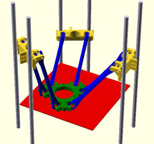
Typical column Delta architecture with three parallelogram arms:
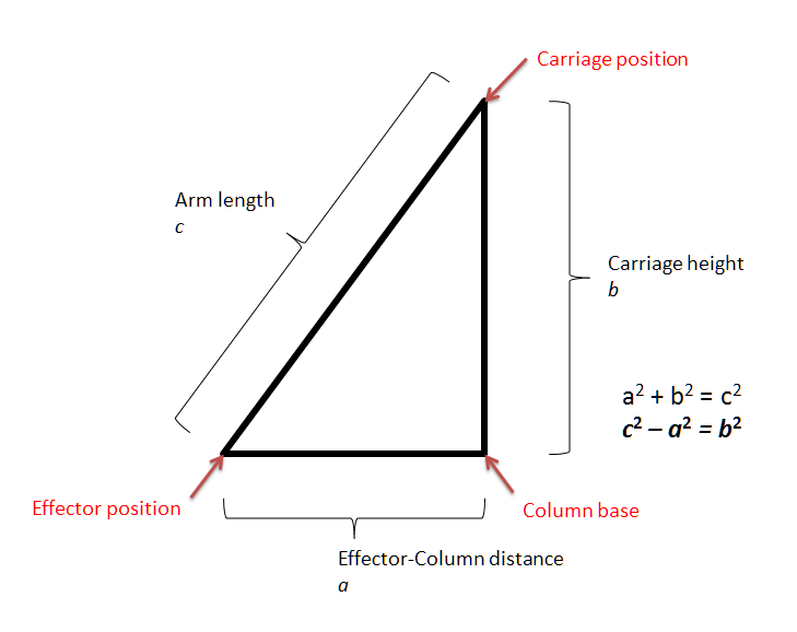
Kinematic simplification (removing static offsets & reducing parallelograms to simple arms):


The basics of delta kinematics are surprisingly simple. The effector sits at the intersection of the three arms. The arms are controlled by shifting their attachments to the columns (carriages) up and down. Move a carriage upward, and the effector will swing towards the corresponding column. Each point in space has a unique carriage position for each of the three columns. It's conceptually very straightforward, even if the math is a bit complex.
Most Delta firmwares (eg Marlin, Repetier) determine the effector location relative to each column and use the Pythagorean theorem to find the corresponding carriage height required. There are some square and square root operations. Repeat for all three columns and you have the desired carriage positions.
Once the start position and end positions of each carriage is known, the firmware simply linearly interpolates the carriage position to drive the motion. But driving the carriages at constant speed between start & end positions causes path error, because the intermediate carriage positions on the tool path are not linear between the start and end. The longer the segment, the more error at the middle of the path due to linear interpolation of the desired arc path. Specifically, executing long segments (such as travel moves) will dip the nozzle down towards the build plate in an arc. This is likely to cause nozzle/print collisions. So the firmware uses segmentation to improve intermediate path accuracy.

Segmentation works by splitting each segment into smaller sub-segments. Very short segments have little error. Typical firmware sets a segments-per-second value and subdivides anything longer than the preset value.
One significant result of this is that Deltas must do an enormous amount of math to execute even simple linear toolpaths. This places significant computational strain on older 16 bit processors. Various improvements to this exist, such as using integer math to speed calculations (Repetier) or upgrading to faster, more-capable 32 bit systems (Smoothie). But the fact remains that most Delta firmware uses an inefficient kludge for kinematics calculations.
I think I have a better option figured out. It's an exact inverse kinematics solution -- no interpolation -- that looks like it might be capable of executing faster than the simplified kinematics with segmentation. But I'm not an expert on the coding side of things. Input would be appreciated.
Let's look at the real (generalized) kinematics that Deltas use, rather than the simplified version. First, each arm defines a sphere of positions where the effector can be for any given carriage position. Or, more strictly, a segment of sphere with radius of the arm's length, and other dimensions based on joint constraints. The sphere of possible effector positions moves up and down with the associated carriage. Here's the sphere section for one carriage at one position:
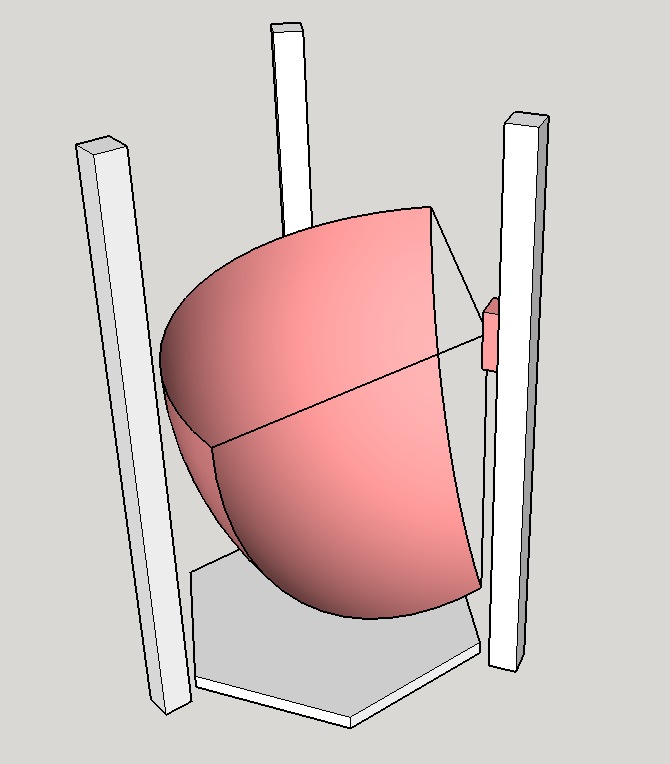
This "sphere of freedom" is one constraint for the effector in 3d space, so one arm confines the effector to the two-dimensional surface of the sphere. Adding a second carriage & arm adds another sphere and further constrains the effector. The intersection of two spheres is a circle. So with two arms and carriages fixed in place, the effector must sit on a circular arc segment (one-dimensional curve).

Adding the third arm forces the effector to sit at the intersection of three spheres sections, which is a point. So the carriage positions (sphere centers) and rod lengths (sphere radii) uniquely define the effector location in space.

So far, this is exactly how the typical firmware kinematics work, but explained in a slightly different way. The sphere radius is the hypotenuse in the triangle calculation. So you can use the Pythagorean theorem to associate an effector location with a set of carriage positions. But what I want to add is the analytical solution for the motion curves between discrete points.
When the carriages move up and down, the associated spheres move up and down too. All Delta robot motion is produced by translations of the three spheres. Column Deltas use vertical translations. Clavel's Delta (rotary arm, usually used for pick-and-place) translates the spheres along circular arcs. Other Delta styles exist, and they all operate by translating spheres.
There is only one possible position for each carriage at each effector location. That means we can do the kinematics math for each arm/carriage separately, with no other interactions between them. So let's consider how a single carriage must move to produce a particular tool path in the effector. The simple version is, the effector must sit on the surface of the sphere. Which means the carriage must move up or down such that the sphere intersects with the tool path segment.
We can represent this relationship by taking the tool path segment, and projecting it along the Z axis into a vertical plane section. That plane section intersects the sphere to produce a circular arc segment. (Plane/sphere intersections produce circles.) The Z distance between the desired tool path and this intersection arc segment is how far the carriage must travel to produce the desired motion.

What this shows us is that producing a straight line effector motion requires the carriage to travel at a non-linear rate. The graph of carriage height with respect to time will be a circular arc, which is a mathematically tractable curve to produce via software. For example, the motion curve could be produced using some sort of sine function that I haven't derived yet. But what's really interesting is the possibility of adapting the Bresenham's circle algorithm (http://en.wikipedia.org/wiki/Midpoint_circle_algorithm) to step out the circular arc with respect to time. That is a well-known and well-optimized function that can step through a circle shape without redoing the full kinematics calculation at every intermediate point.
Of course, the circular motion path is only valid for horizontal effector motion. To add in effector Z motion, we have to sum a linear motion with a circular motion. That should be a relatively straightforward modification to Bresenham's though. (Or the tool segment can be split into horizontal-circular and vertical-linear components which are run through Bresenham's separately.)
So, for each tool path segment, I'm thinking we would need to:
- Find the start and end carriage positions (same as simplified Delta kinematics)
- Project the end point down in Z to find the point on the sphere representing the final carriage position
- Find a third point on the virtual circle, eg project the segment midpoint down in Z
- Find the radius of the circle arc using the three points previously determined
- Plug the start/end points and circle radius into a modified Bresenham's circle algorithm to step out carriage motion with respect to time
- Repeat for other two carriages
It's quite a few extra math steps versus a single segment for typical Delta firmware, but I think the math steps should be similar or lower CPU cycle count. And segmentation is not required, so the square roots to determine carriage endpoints are not being repeated 100-200 times per second. That may allow significant processing speed increases on straight-line tool paths.

Whosa whatsis
Dec 14, 2014, 6:00:03 PM12/14/14
to 3dp-...@googlegroups.com
Very minor correction, the Atmega microcontrollers we typically use are 8-bit, not 16-bit. The XMEGA series is some kind of mixture of 8- and 16-bit.
Interesting thinking of the effector position as the intersection of three spheres centered on the carriages. It's probably better to think of it as three hemispheres, since there are actually two solutions for each effector position, and you don't want the arms trying to cross singularities. It actually seems like it might be more useful to think of each of the carriage positions as the intersection of a line with a hemisphere centered on the effector. I don't know how the algorithm optimization compares, but I did my own deltabot simulation in OpenSCAD a while back that used sine, cosine and their inverse functions instead of the pythagorean theorem for calculating carriage position. It seems that this approach would be more conducive to the type of non-linear interpolation you're suggesting, but I haven't looked very deeply into it or into how well-optimized the trigonometry functions on the microcontrollers are (though I suspect that somebody probably did at some point, and decided to go with the pythagorean theorem instead for that reason).
Ryan Carlyle
Dec 14, 2014, 6:06:23 PM12/14/14
to 3dp-...@googlegroups.com
I wouldn't over-estimate the amount of thought that went into the kinematics in Marlin et al -- it's mostly unchanged since the first "hacked together" version was made a few years back. I'm not as familiar with Smoothie and LinuxCNC code though.

Dan Newman
Dec 14, 2014, 9:42:19 PM12/14/14
to 3dp-...@googlegroups.com
On 14/12/2014, 3:00 PM, Whosa whatsis wrote:
> Very minor correction, the Atmega microcontrollers we typically use are
> 8-bit, not 16-bit. The XMEGA series is some kind of mixture of 8- and
> 16-bit.
>
> Interesting thinking of the effector position as the intersection of three
> spheres centered on the carriages. It's probably better to think of it as
> three hemispheres, since there are actually two solutions for each effector
> position, and you don't want the arms trying to cross singularities. It
> actually seems like it might be more useful to think of each of the
> carriage positions as the intersection of a line with a hemisphere centered
> on the effector. I don't know how the algorithm optimization compares, but
> I did my own deltabot simulation in OpenSCAD a while back that used sine,
> cosine and their inverse functions instead of the pythagorean theorem for
> calculating carriage position. It seems that this approach would be more
> conducive to the type of non-linear interpolation you're suggesting, but I
> haven't looked very deeply into it or into how well-optimized the
> trigonometry functions on the microcontrollers are (though I suspect that
> somebody probably did at some point, and decided to go with the pythagorean
> theorem instead for that reason).
sqrt() in avr libc is a pretty consistent 492 cycles since there's a very
> Very minor correction, the Atmega microcontrollers we typically use are
> 8-bit, not 16-bit. The XMEGA series is some kind of mixture of 8- and
> 16-bit.
>
> Interesting thinking of the effector position as the intersection of three
> spheres centered on the carriages. It's probably better to think of it as
> three hemispheres, since there are actually two solutions for each effector
> position, and you don't want the arms trying to cross singularities. It
> actually seems like it might be more useful to think of each of the
> carriage positions as the intersection of a line with a hemisphere centered
> on the effector. I don't know how the algorithm optimization compares, but
> I did my own deltabot simulation in OpenSCAD a while back that used sine,
> cosine and their inverse functions instead of the pythagorean theorem for
> calculating carriage position. It seems that this approach would be more
> conducive to the type of non-linear interpolation you're suggesting, but I
> haven't looked very deeply into it or into how well-optimized the
> trigonometry functions on the microcontrollers are (though I suspect that
> somebody probably did at some point, and decided to go with the pythagorean
> theorem instead for that reason).
deterministic and clever algorithm for doing sqrt() on binary logic. Sine and
cosine; however, are on average 3353 cycles on AVR2 architectures and 1653
cycles on AVR4 architectures. (The AVR4's have 8bit multiply instructions.)
avr libc's math code is a straightforward port of gcc's libm to
AVR assembler. Pretty safe that way -- less likely to have bugs. However,
for 8bit hardware with no floating point, implementing the CORDIC techniques
would have been faster. Indeedm is known to be faster since there is at least
one implementation for AVR hardware and used because it is faster. I do not,
though, have timings of those CORDIC implementations. I suspect that a single
sine or cosine would be faster than the 492 cyles for a single sqrt. But that
would just be for a single one. You probably lose relative to a single sqrt as
soon as you need two (or more) sine or cosines or combination thereof.
Dan
Ryan Carlyle
Dec 14, 2014, 11:23:35 PM12/14/14
to 3dp-...@googlegroups.com
Yeah, doing a sine every interrupt tick is probably not going to happen then.
whosawhatsis
Dec 15, 2014, 12:27:55 AM12/15/14
to Ryan Carlyle, 3dp-...@googlegroups.com
Yeah, sounds that way, though I do wonder if the optimization compares differently on ARM-based controllers.
--
You received this message because you are subscribed to a topic in the Google Groups "3DP Ideas" group.
To unsubscribe from this topic, visit https://groups.google.com/d/topic/3dp-ideas/chNECxNNgsg/unsubscribe.
To unsubscribe from this group and all its topics, send an email to 3dp-ideas+...@googlegroups.com.
To post to this group, send email to 3dp-...@googlegroups.com.
To view this discussion on the web visit https://groups.google.com/d/msgid/3dp-ideas/f745cc37-db52-45ba-8882-3e538c5c9c55%40googlegroups.com.
For more options, visit https://groups.google.com/d/optout.

Colin Wallace
Dec 15, 2014, 1:15:16 AM12/15/14
to 3dp-...@googlegroups.com
I'd just like to point out that even if the solution is a sinusoidal function, that doesn't necessarily mean you have to make a call to the sin(x) function every interrupt. There are quite a few ways to trace out a sine function efficiently.
Quick example: if the solutions were such that you need to calculate sin(x) for x=1, 2, 3, ..., you would make use of the identity e^(ix) = cos(x) + isin(x) and the fact that e^(i(x+1)) = e^i * e^(ix). So if you evaluate e^i once, then you can now iteratively compute each value you need of sin(x) with just one complex multiplication for each value of x. I would guess you could get at least 100 iterations out of that before any propagated rounding errors became even remotely noticeable.
But I think we should derive a mathematical solution before we focus on the implementation details.
Ryan Carlyle
Dec 17, 2014, 4:50:07 PM12/17/14
to
More details on the error due to linear interpolation.
When each carriage follows a linear path (linear in time, eg constant carriage velocity) between start and end segments, the effector dips below the desired path. As mentioned previously, "segmentation" is used to make the linear interpolated path closely follow the exact path and reduce this error to an acceptable level. But here's what happens if you don't use segmentation.
Consider a simple horizontal tool path. All three arm spheres are shown. The tool path starts at the intersection of the three spheres (the current effector location).
In order for the effector to move to the desired endpoint, the spheres must translate up/down (by moving carriages up/down) so that the new sphere intersection lies at the desired endpoint. Red carriage must move up for its sphere to intersect the endpoint:

Yellow carriage must move down:

Blue carriage must move up:

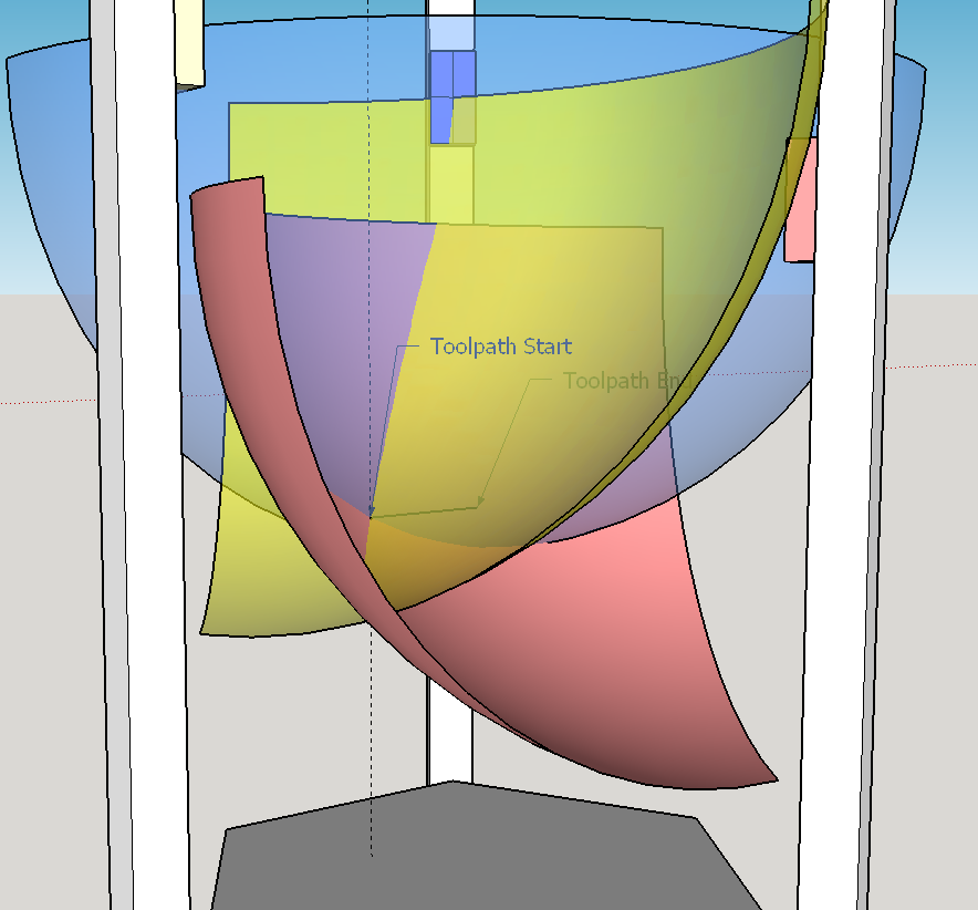
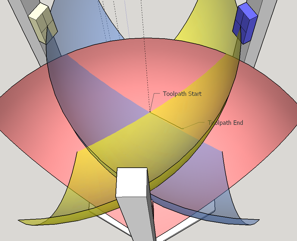
When you combine the three motions, the effector moves from the start point to the desired endpoint. Following the exact motion path would require the carriages to move at a non-linear rate, as described earlier in this thread. But if they move linearly, the difference between the straight line path and exact arc path will produce effector position error. Here's an illustration for one carriage of the curve representing the exact path, versus the linear interpolated path. The white face is the tool path projected downward in Z to form a plane, and the "exact carriage path" arc is the intersection of that plane and the sphere:

The actual effector error is found by combining these three carriage error curves. The maximum carriage error will always be found at the midpoint of the toolpath segment because a circular arc and its inscribed chord always have their maximum separation at the midpoint. The magnitude of the error will depend on the radius of the exact path arc and the length of the motion segment. In other words, long segments far away from the column will introduce the most carriage error.

Because we only use the lower parts of the arm spheres (and do not allow arms to tilt above horizontal) the exact path arc is always concave-up. This means the interpolation will always introduce insufficient upward carriage travel, which means the effector always dips downward below the desired path.
Some straightforward geometry based on chord height and basic trigonometry finds the magnitudes of carriage position errors very easily. But each carriage will have a different amount of error. This means the effector will not only dip downwards, but will also move horizontally off the desired path. In general, lowering a single carriage pushes the effector away from that column. Which means the effector will move away from the carriage that has the largest error (farthest below where it should be). And the carriage with the largest error should be the one with the smallest exact path arc radius, which is the carriage whose column is farthest from the desired tool path segment. So we should expect segmentation error to deflect the effector path outward away from the center of the build plate.
Linear interpolation error shifts the effector down and out from the desired tool path, with maximum error at the tool path segment midpoint.
To find the magnitude and exact direction of carriage position error, all that is required is calculating the position of each carriage at the interpolated midpoint (by averaging the start and end carriage positions). Then calculate the forward kinematics at the interpolated midpoint, and compare it against the desired tool path midpoint. That will give an exact solution to the interpolation error.
Reply all
Reply to author
Forward
0 new messages