Dual hob extruders
959 views
Skip to first unread message

Ryan Carlyle
Jun 26, 2015, 8:15:01 PM6/26/15
to 3dp-...@googlegroups.com
Right, so, I've been playing with a couple different dual-hob extruder design concepts for the past few days. You know, putting two drive gears on either side of the filament to double the grip force. My goal is to come up with a design that:
- Can tolerate large variation in filament diameter, eg for people who make their own filament
- Can tolerate slightly different drive gear diameters
- Runs off one motor
- Doesn't infringe Stratasys patents/applications (for example, the popular Bondtech dual-hob extruder may be impacted by a pending Stratasys patent application that was published a few months before Martin Bondeus says he started his design)
- If possible, gets "grip assist" force from forward-filament-pushing force (like my B'struder)... but of course not so much that retractions lose grip
- If possible, is low-backlash... although this one doesn't matter much
I'm still working on layout and printed parts design for the first rev. But this is such a lovely-complicated design that I have to post a screen grab. TEN 625 BEARINGS, YEAH!

If you're wondering why the gears look weird, it's because I drew the pitch diameter into the tooth profile for visual spacing purposes.

Bob Bilbrey
Jun 27, 2015, 2:23:38 PM6/27/15
to 3dp-...@googlegroups.com
I'd like to see a practical, easily implemented method of comparing extruder performance that we could all (most) use. Perhaps there is one out there but I've not seen it. It would need to ignore hot end/nozzle variance and, I think just focus on force/feed rate/mass/stall-before-strip/parts-count/cost-of-goods and probably a few other factors ( COG is a really tough one to quantify but very important ). Or we might settle for free-air extrusion rates using an agreed upon widely used hot-end ( such as E3D v6 or something ) controlling for filament type/diameter, temperature, nozzle diameter. If we had some agreement on this it should be easy to create an Excel table to which participants could post results. I intuitively go for free-air as very easy to implement and "someone" could also compile a free-air normalization table between ,say, our putative baseline E3D and other commonly used hot-ends ( http://reprap.org/wiki/Hot_End_Comparison ). Any thoughts ?
Ryan Carlyle
Jun 27, 2015, 3:46:44 PM6/27/15
to 3dp-...@googlegroups.com, rmbi...@gmail.com
Extruder drive benchmarking is a super important subject. I've been putting a lot of thought into it during book chapter research. I've seen a few different techniques:
- Use the drive to pull filament against a force sensor (stationary pull)
- Free-air extrude at different speeds, weigh the output on a sensitive scale, and record how much extrusion drops with speed
- Install a strain gauge between the filament drive and a bowden tube, and measure live while printing
These all kind of suck. Stationary pulls don't show speed-dependent under-extrusion or loss of torque. Neither stationary pulls nor free-air extrusion measure retraction capability at all. The live strain gauge is really useful for understanding real behavior, but is so dependent on your chosen print settings that it's not a very good way to generate anything resembling a universal benchmark.
My thought is to just use the extruder to lift weights at various speeds and acceleration settings. Just tie the filament around a 5,10,15 lb weight, and pick it up at 5,20,50mm/s. Whatever weights and speeds give a good range. Then measure the actual distance versus no-load distance. You can check the max acceleration, max speed, max speed change (velocity delta), etc. Then you generate some charts like this:

Using this curve, you can then hook the extruder back up to a printer, do your free-air extrusion at increasing rates until it skips steps, and look that speed up on the velocity performance chart to find the equivalent pushing force. This lets you approximately compare backpressure force for different bowden tubes, hot ends, and nozzle sizes. No special equipment or load cells required. Just an extruder clamped to the edge of a table, some weights, acceleration setting changes, and gcode commands
Anyway, back to the hardware. Design progress from last night:


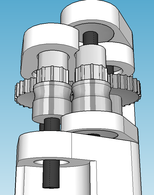
One hob and the first three gears are fixed to the stepper. The third gear axle doubles as a hinge pivot for the spring-arm. The spring arm forces the second hob towards the first hob to pre-load the filament bite. Forward drive torque then assists the spring arm through the geartrain and applies additional bite force.
Yes, rapid filament diameter variation will cause a little bit of phase error between the hobs due to the angular displacement of the spring arm affecting the fourth gear position, but I don't think that will matter.
This design could be a lot more compact if I weren't using 625 bearings for all the shaft supports and a 5x5mm or 5x8mm helical coupler to attach the stepper. For example, a longer motor shaft or using custom gear+hob parts like Printrbot and Bondtech would cut the length in half. But this is a prototype and it's going to be a Bowden drive, so I'm not real worried about size.
Ryan Carlyle
Jun 27, 2015, 3:51:07 PM6/27/15
to 3dp-...@googlegroups.com, temp...@gmail.com, rmbi...@gmail.com
The other issue with benchmarking is whether you're really trying to benchmark solely the extruder drive mechanism or the stepper motor + extruder drive system. I suspect that the extruder drive itself (hob, idler, etc) primarily affects the PEAK grip force and the force-dependent flow efficiency. As long as you maintain grip, the speed, speed change, and acceleration parameters are much more about the attached stepper drivetrain than the drive itself.
Bob Bilbrey
Jun 27, 2015, 8:29:07 PM6/27/15
to 3dp-...@googlegroups.com, rmbi...@gmail.com
Or possibly a dynamometer with a filament wrapped multiple turns around a capstan ( say 6 inch dia ). Could be made either with a geared generator with an encoder dissipating into a resistive load. Or a back loaded DC motor with an adjustable power supply again with an encoder. The speed/load values are pretty modest and the run times can whatever you wish as long as you don't overheat. The thing I like about this approach is that you can dial in values as you go and sneak up on things. With a static weight ( admittedly simpler ) the individual setups can be more time consuming and the run durations limited upon what floor of the building you are hanging out of. Changing subjects - I typically attempt to evaluate all encompassing data collection thus my inclusion of COG data etc. Most surely it is by reason of my long toil in mechanical product design where application to market and all that entails governs the direction. In contrast, I suppose, to the research oriented approach which can be much more limited in focus.

Wing Wong
Jun 27, 2015, 9:36:44 PM6/27/15
to 3dp-...@googlegroups.com
What about measuring back pressure when nozzle is moving at a certain distance above a plate?
I'm wondering if there is a significant difference in results between a filament drive that is pulling vs pushing, and air-extrusion vs .1, .2, etc. distance extrusion.
W.
--
You received this message because you are subscribed to the Google Groups "3DP Ideas" group.
To unsubscribe from this group and stop receiving emails from it, send an email to 3dp-ideas+...@googlegroups.com.
To post to this group, send email to 3dp-...@googlegroups.com.
To view this discussion on the web visit https://groups.google.com/d/msgid/3dp-ideas/d6cf6116-36f5-4ca0-bd86-673fae4e0d95%40googlegroups.com.
Ryan Carlyle
Jun 28, 2015, 12:30:18 AM6/28/15
to 3dp-...@googlegroups.com, winge...@gmail.com
Wing, when you say measuring back pressure, what are you thinking? Like an Airtripper force sensor style setup, or actually trying to measure pressure!
Wing Wong
Jun 28, 2015, 6:41:03 AM6/28/15
to Ryan Carlyle, 3dp-...@googlegroups.com
Was thinking of actually trying to measure the back pressure, but no ideal how that would work... but yeah, if you are going to gather metrics, would be nice to be able to get the data point from the source.
Maybe that induction sensor and a metal diaphram and have it measure minute deflections?
W.
On Sat, Jun 27, 2015 at 9:30 PM, Ryan Carlyle <temp...@gmail.com> wrote:
Wing, when you say measuring back pressure, what are you thinking? Like an Airtripper force sensor style setup, or actually trying to measure pressure!
--
You received this message because you are subscribed to the Google Groups "3DP Ideas" group.
To unsubscribe from this group and stop receiving emails from it, send an email to 3dp-ideas+...@googlegroups.com.
To post to this group, send email to 3dp-...@googlegroups.com.
To view this discussion on the web visit https://groups.google.com/d/msgid/3dp-ideas/d31fbebf-b435-40c1-a974-fa5efe595d71%40googlegroups.com.

Jetguy
Jun 29, 2015, 12:21:11 PM6/29/15
to 3dp-...@googlegroups.com, temp...@gmail.com
Sorry if I'm negative but my biggest worry with this is gear wear. On first thought, you write it off as no big deal, this seems to be a low stress application, we shouldn't be seeing a lot of wear.
Reality is, many brands such as Makergear has seen significant and even catastrophic failures of gear trains in, what from the outside, very high precision planetary 5:1 steppers.
Between the vibration of the motor, and just the huge amount of rotation they actually see in real world printing conditions, the pinions flat out wear out- even with grease.
These external gears, out in the open, subject to contamination and lack of lube, further the method and teeth hardness they are made from drives up the cost to produce something viable.
Again, I have actually seen such wear and most designs suffer in that in order to make the parts cheaply, they just hog the hob and t
Ryan Carlyle
Jun 29, 2015, 1:42:30 PM6/29/15
to 3dp-...@googlegroups.com, vernon...@gmail.com
Yeah, all good points Jetguy, I'm not trying to put this on a commercial product, just experiment with designs a bit. I ordered aluminum gears... If they make it 500 hours I'll be happy.
Ryan Carlyle
Jun 29, 2015, 4:41:28 PM6/29/15
to 3dp-...@googlegroups.com, temp...@gmail.com, vernon...@gmail.com
Raises an interesting point... how would you endurance-test an extruder system? In a perfect world, you'd do 1,000-10,000 hours of actual printing, but that's unreasonable for anything but a major commercial product release. What sort of automated testing could we come up with?
I'm imagining a special loop of an extremely flexible filament like a TPE or one of the softer nylons (made by fusing the free ends together) which is not deformed by the drive gear. And then use the extruder to drive the loop against a drag-clutch (or a free-wheeling extruder stepper) to apply some back-force on the drive mechanism. Then you just run a gcode file with a few weeks of alternating motion and see what happens.
Realistically, you could probably just replace the drive hob with a belt pulley if the main goal is testing the drivetrain.

whosawhatsis
Jun 29, 2015, 5:19:19 PM6/29/15
to Ryan Carlyle, 3dp-...@googlegroups.com
Aaron Double (AKA TwoTimes) had a similar design back in the old days, I believe it was designed as a replacement mechanism for the Mk4 extruder. Unfortunately, he removed all of his stuff from Thingiverse and AFAIK hasn't re-posted it anywhere. It's an old enough design that it's probably not useful for much anymore beyond prior art, and since it's no longer posted publicly with timestamps, I'm not sure it would hold up for that purpose (which is part of the reason that I didn't do the same with my designs).
--
You received this message because you are subscribed to the Google Groups "3DP Ideas" group.
To unsubscribe from this group and stop receiving emails from it, send an email to 3dp-ideas+...@googlegroups.com.
To post to this group, send email to 3dp-...@googlegroups.com.
To view this discussion on the web visit https://groups.google.com/d/msgid/3dp-ideas/7c75babf-0dd8-423d-85dc-b24db3188f64%40googlegroups.com.
Ryan Carlyle
Jun 29, 2015, 5:55:57 PM6/29/15
to 3dp-...@googlegroups.com, whosaw...@gmail.com
You know the Wayback Machine has a lot of old Thingiverse crawls?

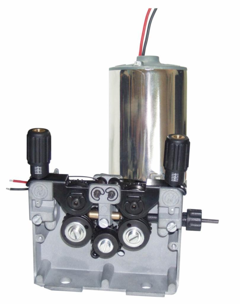
That the one you're talking about? It's a near-exact copy of an old MIG wire feed mechanism design.
On Monday, June 29, 2015 at 4:19:19 PM UTC-5, Whosa whatsis wrote:
Aaron Double (AKA TwoTimes) had a similar design back in the old days, I believe it was designed as a replacement mechanism for the Mk4 extruder. Unfortunately, he removed all of his stuff from Thingiverse and AFAIK hasn't re-posted it anywhere. It's an old enough design that it's probably not useful for much anymore beyond prior art, and since it's no longer posted publicly with timestamps, I'm not sure it would hold up for that purpose (which is part of the reason that I didn't do the same with my designs).On Friday, June 26, 2015 at 17:15, Ryan Carlyle wrote:
Right, so, I've been playing with a couple different dual-hob extruder design concepts for the past few days. You know, putting two drive gears on either side of the filament to double the grip force. My goal is to come up with a design that:--
- Can tolerate large variation in filament diameter, eg for people who make their own filament
- Can tolerate slightly different drive gear diameters
- Runs off one motor
- Doesn't infringe Stratasys patents/applications (for example, the popular Bondtech dual-hob extruder may be impacted by a pending Stratasys patent application that was published a few months before Martin Bondeus says he started his design)
- If possible, gets "grip assist" force from forward-filament-pushing force (like my B'struder)... but of course not so much that retractions lose grip
- If possible, is low-backlash... although this one doesn't matter much
I'm still working on layout and printed parts design for the first rev. But this is such a lovely-complicated design that I have to post a screen grab. TEN 625 BEARINGS, YEAH!
If you're wondering why the gears look weird, it's because I drew the pitch diameter into the tooth profile for visual spacing purposes.
You received this message because you are subscribed to the Google Groups "3DP Ideas" group.
To unsubscribe from this group and stop receiving emails from it, send an email to 3dp-ideas+unsubscribe@googlegroups.com.
whosawhatsis
Jun 29, 2015, 5:59:11 PM6/29/15
to Ryan Carlyle, 3dp-...@googlegroups.com
Forgot about Wayback. Yeah, that's the one I was thinking of.
To unsubscribe from this group and stop receiving emails from it, send an email to 3dp-ideas+...@googlegroups.com.
To view this discussion on the web visit https://groups.google.com/d/msgid/3dp-ideas/16ac1a40-e2e2-4f2f-bcc7-11067cc352ef%40googlegroups.com.
Ryan Carlyle
Jul 11, 2015, 11:01:31 PM7/11/15
to 3dp-...@googlegroups.com, whosaw...@gmail.com, temp...@gmail.com
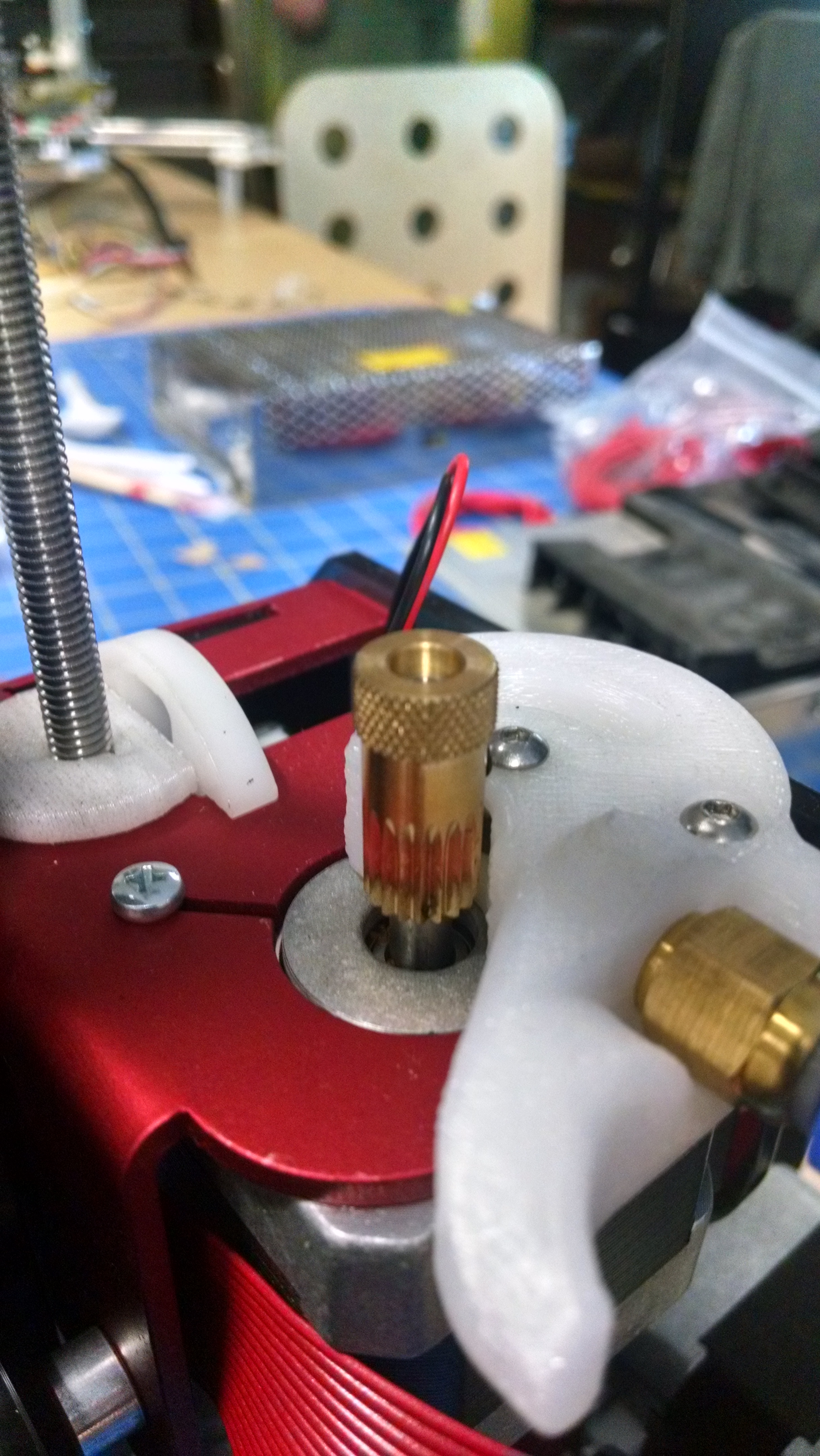
Coming along nicely...

The parts count and design complexity on this thing is bordering on silly, but it's really fun to see it coming together.

Mikk Kiilaspää
Jul 12, 2015, 3:45:53 AM7/12/15
to 3dp-...@googlegroups.com, whosaw...@gmail.com
What happened to the teeth of the gear in the foreground?
Ryan Carlyle
Jul 12, 2015, 11:57:53 AM7/12/15
to 3dp-...@googlegroups.com, mik...@gmail.com
That's just how SDP-SI cut the gear to get the set screw shoulder the right diameter. The tooth root diameter is smaller than the set screw shoulder, so they cut the tooth roots through the set screw area to save cost presumably. That's kind of what happens when you need a gear with 5mm bore and <10mm pitch diameter.
Ryan Carlyle
Jul 12, 2015, 3:36:57 PM7/12/15
to 3dp-...@googlegroups.com, temp...@gmail.com
I need to tweak some dimensions, as well as design the tensioner spring and bowden fitting sections. Everything seems more or less functional though.


Embarrassingly, I had the wrong hob geometry in my model for my drive gears, and didn't realize the Makerbot mk7 drive gear cannot be doubled-up like this because the hob is too deep. So I switched to some random ebay mk7 knock-off with a shallower hob. Should
Whosawhatsis
Jul 12, 2015, 8:11:29 PM7/12/15
to Ryan Carlyle, 3dp-...@googlegroups.com
Yeah, with 3mm filament it should work, but you don't want a deep groove for 1.75. I was actually thinking this would be a good application for those grooveless gears with the sandpapery surface. I think robotdigg sells them. Without the groove, you'll have to enclose the rest of your filament path really well, of course.
--
You received this message because you are subscribed to the Google Groups "3DP Ideas" group.
To unsubscribe from this group and stop receiving emails from it, send an email to 3dp-ideas+...@googlegroups.com.
To post to this group, send email to 3dp-...@googlegroups.com.
To view this discussion on the web visit https://groups.google.com/d/msgid/3dp-ideas/9e8ccf67-bf1a-48ec-9f1b-8e122f7699b2%40googlegroups.com.

Brad Hopper
Jul 13, 2015, 10:49:28 PM7/13/15
to 3dp-...@googlegroups.com
The e3d hobb goblins are nice and shallow and will work for dual hobb on 1.75mm
Ryan Carlyle
Jul 13, 2015, 11:31:27 PM7/13/15
to 3dp-...@googlegroups.com, brad....@gmail.com
Hmm, just looking at the product photo, the hob diameter is too small for any reasonable size of gear to fit on the same shaft. With this particular design, the major diameter of the small sync gears needs to be smaller than the drive gear / hob.
Tatsus might work, not sure, both my 5mm Tatsus are in my Clone R1 at the moment.
whosawhatsis
Jul 14, 2015, 12:12:20 AM7/14/15
to Ryan Carlyle, 3dp-...@googlegroups.com, brad....@gmail.com
Tatsu mini would have a shallow enough groove, but it has a small diameter, and you'd also have to remove the knurled knobs to fit two of them together. Regular tastu/tatsu 2 gears aren't any shallower than anything else, they just have a wider groove (on tatsu 2) to mitigate issues caused by the difference in gear diameter between the center and the sides.
I've done test fits with a lot of drive gears in dual-hob configurations, and none of the grooved ones I've tried are shallow enough for 1.75. You'll probably have to choose a straight-toothed gear. If you could match effective diameters with two difference gears, you could use one straight and one hobbed, but even with everyone trying to match the effective diameter of the MBI gears, you're unlikely to find a perfect match.
I've also been thinking that this might be a good application for a knurled drive like the Ultimakers use. They have problems with consistency of the effective diameter when there's a lot of back-pressure, but I've been thinking that using two of them might mitigate that. The advantage is that they seem to be self-cleaning, which is nice in an extruder this complicated.
On Monday, July 13, 2015 at 20:31, Ryan Carlyle wrote:
Hmm, just looking at the product photo, the hob diameter is too small for any reasonable size of gear to fit on the same shaft. With this particular design, the major diameter of the small sync gears needs to be smaller than the drive gear / hob.Tatsus might work, not sure, both my 5mm Tatsus are in my Clone R1 at the moment.
--You received this message because you are subscribed to the Google Groups "3DP Ideas" group.To unsubscribe from this group and stop receiving emails from it, send an email to 3dp-ideas+...@googlegroups.com.To post to this group, send email to 3dp-...@googlegroups.com.
To view this discussion on the web visit https://groups.google.com/d/msgid/3dp-ideas/a98e2ae8-d475-47a3-82c9-f9b8ca69171f%40googlegroups.com.
Ryan Carlyle
Jul 14, 2015, 1:55:12 PM7/14/15
to 3dp-...@googlegroups.com, whosaw...@gmail.com
Hmm, Tatsu might actually work by stagging the hobs, but that seems like a bad idea.
The ebay "mk7" drive gears I'm using actually do double-grip on 1.75mm filament, but heaven knows if it's a sustainable supply with consistent diameters. I bought them about a year ago.
Ryan Carlyle
Jul 29, 2015, 9:59:13 PM7/29/15
to 3DP Ideas, temp...@gmail.com, temp...@gmail.com
Minor update -- Ultibots sells a 1.75mm hob that can double-bite. I picked up a few.
Whosawhatsis
Jul 29, 2015, 10:55:36 PM7/29/15
to Ryan Carlyle, 3DP Ideas
I visited Deezmaker the other day and saw a prototype they were trying of a Tatsu Mini with almost no knob for the knurled portion, which would probably work (bonus, you could also try using the knurled portion to grab the filament as a self-cleaning hob). It was a prototype from the machine shop and not in production, so you can't buy one (not yet, at least). The knurl isn't as useful because it's harder to grip and turn when it's so small, but since it's going to be cheaper to produce, they might switch to them anyway (the picture also shows the springless nylon idler that they seem to have pushed into production, despite my fighting tooth-and-nail while I was there to keep the version with a real spring).
To view this discussion on the web visit https://groups.google.com/d/msgid/3dp-ideas/c146e7e5-1495-4b24-b4bb-263c5720fa0a%40googlegroups.com.
Ryan Carlyle
Jul 30, 2015, 10:55:49 AM7/30/15
to 3DP Ideas, whosaw...@gmail.com, whosaw...@gmail.com
Hmm, does that have any groove or is it just straight teeth?
Using two straight-tooth hobs does have some appeal for this application, but getting filament fed sounds unpleasant. Particularly flexibles.
whosawhatsis
Jul 30, 2015, 6:09:41 PM7/30/15
to Ryan Carlyle, 3DP Ideas
The teeth are straight to the edge of the gear.

Chris P
Aug 4, 2015, 9:23:31 AM8/4/15
to 3DP Ideas
At the risk of a derail (tell me if I should start another thread), couldn't we gain similar advantages vs dual hobs by simply using a hob and idler pulley with larger diameters? That way we have more teeth in contact with the filament at any given time.
And yes - for direct drive systems this approach is less feasible since it increases the extruder packaging size and mass. But for bowdens I think it's a feasible alternative.
Chris
whosawhatsis
Aug 4, 2015, 2:32:20 PM8/4/15
to Chris P, 3DP Ideas
You could do that, though there's also something to be said for having a smaller number of very sharp teeth in contact, so that they can concentrate force to bite deeply. Of course, the benefit of large-diameter drive gears really comes into play when the diameter is greater than the minimum bend radius of the filament, so that you can wrap the filament around a significant portion of its circumference rather than just running it at a tangent to the gear.
For completeness, It's probably also worth mentioning Shauki B's "double force" (I've tried to explain the difference to him, but his English isn't great) extruder here: https://plus.google.com/u/0/+ShaukiB/posts/NsdBRmWcaun
--
You received this message because you are subscribed to the Google Groups "3DP Ideas" group.
To unsubscribe from this group and stop receiving emails from it, send an email to 3dp-ideas+...@googlegroups.com.
To post to this group, send email to 3dp-...@googlegroups.com.
To view this discussion on the web visit https://groups.google.com/d/msgid/3dp-ideas/9350b4c6-5519-4766-b1cf-6ebb96bf107f%40googlegroups.com.
Chris P
Aug 4, 2015, 2:42:50 PM8/4/15
to 3DP Ideas
My thinking was I was always told for optimum bolted connection strength you needed 5-6 threads fully engaged in your nut/tapped hole/whatever. I think a similar logic would apply here.
From another angle, generating sufficient clamping force with the idler to keep the filament engaged in the teeth is not an issue - I can generate enough force to actually flatten out the filament as it passed through the idler. The bottleneck seems to be how much force we can apply from the teeth into the filament. More teeth = more surface area engaged = lower tooth pressure, which should mean the filament can be pushed harder before it's chewed up.
when the diameter is greater than the minimum bend radius of the filament, so that you can wrap the filament around a significant portion of its circumference rather than just running it at a tangent to the gear.
My gut reaction is that the filament is under enough stress due to the teeth and idler force; I wouldn't want to subject it to additional stress by bending it around the feed gear more than a few degrees. But this is a purely gut reaction and I have no math to back it up. It may not matter at all.
Chris
whosawhatsis
Aug 4, 2015, 2:58:21 PM8/4/15
to Chris P, 3DP Ideas
Because the gear is round and the filament runs at a tangent to it, you will never have more than two teeth "fully engaged" (and even then only when the part of the gear facing the filament is exactly between two teeth) unless you wrap the filament around the gear. The stress this causes doesn't depend on the angle of the bend, as you suggest. It depends on the radius of the bend, which is why I said that a very large gear would make this more feasible. Remember that the filament comes spooled (or at least coiled), so it already has a bend radius. If your drive gear had the same radius, there would be no additional stress from bending it (and in fact, even less stress than straightening it the way we usually do).
To view this discussion on the web visit https://groups.google.com/d/msgid/3dp-ideas/99d423c6-f912-4097-a22c-7755d0617f28%40googlegroups.com.
Chris P
Aug 4, 2015, 4:26:46 PM8/4/15
to 3DP Ideas
Because the gear is round and the filament runs at a tangent to it, you will never have more than two teeth "fully engaged"
Technically yes, but the real world is soft and squishy to some degree :-) The filament is going to deform as it goes through the idler/feed gear area so I think you will end up with more tooth engagement than that. Also partial engagement is still helpful in transferring force to the filament. My argument can be rephrased as "a single larger hob is much less complicated than 2 opposing hobs and can potentially get 80%+ of the same results".
Remember that the filament comes spooled (or at least coiled), so it already has a bend radius. If your drive gear had the same radius, there would be no additional stress from bending it (and in fact, even less stress than straightening it the way we usually do).
I think this is only true if you can control the orientation in which the filament unwinds from the spool and feeds through the extruder. Not sure how this could be accomplished easily and reliably?
This whole topic also ties into the "ideal tooth geometry" discussion. You want teeth big enough to maximize force transfer area. But if they're too big you won't have enough of them engaged at once. If they're too small the pressure will be too high, and they clog easily if there is any slip.
Chris
Ryan Carlyle
Aug 4, 2015, 4:39:02 PM8/4/15
to 3dp-...@googlegroups.com
For bolts, the optimal nut thickness is a function of the elasticity of the material. The first round of thread takes most of the load -- but the more the material flexes/deforms, the more threads you load. Steel bolts typically get 5-6 threads because that's the point where [nut length ~= bolt diameter] for typical thread profiles, and that's about the maximum practical number of threads that can carry load for grade-8 steel. Trying to get additional threads to take appreciable load requires straining the steel past its ultimate tensile strength. Once the first thread fails in shear, the entire thread will progressively fail, so there's no point in adding more threads than you can load with the first thread at a yielded-but-not-failed strain level.
For filament, the most load should also be at the first loaded thread (the one closest to the hot end) but filament is so elastic (relatively speaking) that you could have tons of threads taking some load. Particularly for elastic stuff like nylon.
To unsubscribe from this group and stop receiving emails from it, send an email to 3dp-ideas+unsubscribe@googlegroups.com.
whosawhatsis
Aug 4, 2015, 5:00:13 PM8/4/15
to Chris P, 3DP Ideas
You'll notice I put "fully engaged" in quotes. There are, of course, more teeth that are partially engaged. They may even have the teeth still pressed all the way into the grooves that they create, but they don't have the full force of the idler holding them there, and if the filament began to strip and the fully-engaged section, those teeth would slip further out of their grooves. Large, sharp teeth might still grip in this state, while small, dull teeth like the ones on the MBI gears would be more likely to slip out entirely.
Regardless of the ideal spacing of the teeth, I think we can probably agree that each tooth should be as thin and sharp as possible without allowing it to bend under the force of pushing the filament. Because even the softer metals that might be used, such as brass, are so much harder than plastic, the teeth should be very thin and sharp indeed. The spacing between the teeth should be larger than this, though, to maintain the structural integrity of the softer plastic between the teeth, so regardless of the size of the teeth, the teeth should be thinner and sharper than the spaces between them. This is the thinking that went into designing the Tatsu gears, and empirically, I have found them to be much more effective than the many other gears I have tried, particularly the MBI ones.
--
You received this message because you are subscribed to the Google Groups "3DP Ideas" group.
To unsubscribe from this group and stop receiving emails from it, send an email to 3dp-ideas+...@googlegroups.com.
To post to this group, send email to 3dp-...@googlegroups.com.
To view this discussion on the web visit https://groups.google.com/d/msgid/3dp-ideas/d6ccf8e4-726c-4ba7-8c59-ff403f9df1e5%40googlegroups.com.
Ryan Carlyle
Aug 5, 2015, 12:27:25 AM8/5/15
to 3DP Ideas
I'm not entirely sure about wanting really sharp teeth. Rounded/knurled teeth plastically deform the filament without actually cutting it. You don't reach ultimate strength of the filament -- it's all just yield. Which surprised me a lot, but my polariscope stress micrographs show the tooth marks vanishing when the filament is heated, indicating the polymer molecules are able to relax back to the pre-bite condition. (Viscoelastic materials are weird sometimes.)

This yield-not-cut behavior probably means the bite groove is being strengthened by work-hardening / strain-crystallization. (Maybe. Ok, it's a guess.) Whereas if you CUT a notch in the filament, you've created a fracture initiation site for further failure. Crazing / micro-void effects from the plastic being forced apart by the wedging action of the sharp tooth will act as stress raisers for shear failure. (I can SEE crazing occurring with the Tatsu and PLA.) So a few really sharp teeth may promote divot-chewing behavior compared to more, duller teeth.
I'm not saying one is better than the other, just that there are valid arguments either way. I think it will depend a lot on which material you test with, how much residual strain the filament has from manufacture, what kind of pigment load it has, how fast the strain is applied (!), how many cyclic loads you apply (eg repeated stepper skipping), etc. Polymers are complicated.
To unsubscribe from this group and stop receiving emails from it, send an email to 3dp-ideas+unsubscribe@googlegroups.com.
Mikk Kiilaspää
Aug 7, 2015, 2:27:00 AM8/7/15
to 3DP Ideas
Any chance you could test out various types of teeth and compare them with your polariscope to see if your thoughts have a real backing?
To unsubscribe from this group and stop receiving emails from it, send an email to 3dp-ideas+...@googlegroups.com.
Ryan Carlyle
Aug 7, 2015, 10:58:47 AM8/7/15
to 3DP Ideas
Yes, I can do that when I get some time. I hadn't yet because I had the same drive gear in all my bots that were accessible. I've swapped a few since then though.
Ryan Carlyle
Aug 25, 2015, 3:19:47 PM8/25/15
to 3DP Ideas

1) The length of the worm gear allows the extruder shaft to float and conform to filament diameter, unlike a fixed-shaft design (it's just a much more elegant approach than my four-gear swing-arm arrangement shown in the opening post to this thread)
2) Forward-drive force applied to the floating drive shaft by the worm enhances filament grip
Of course, it has all the issues of worm drive extruders, like very low top speed. And the grip-assist force reverses during retractions, so you always need to have higher passive spring force than your worst-case retraction force.
Whosawhatsis
Aug 25, 2015, 9:01:05 PM8/25/15
to Ryan Carlyle, 3DP Ideas
Yeah, I think the retraction issue pretty much kills it, since the grip-assist aspect will work in the opposite direction until all grip is lost. I'm also generally wary of these grip-assist mechanisms because it seems like with any of them, in order for the bite depth to change (gear moving perpendicular to the filament, there also has to be a component to the gear's motion (or in this case the teeth on the circumference of the gear) that is parallel to the filament travel. That is, in order to tighten the grip it has to effectively allow the filament to slip a little bit, under-feeding the nozzle. If the force decreases or the filament gets wider, this then has to occur in the opposite direction. With the variability in the pressure/viscosity/friction of the hot end as well as of the filament's diameter/surface texture and hardness, I can imagine the drive gear ending up moving back and forth a lot more than I'd like (the amount I'd like, of course, being not at all).
--
You received this message because you are subscribed to the Google Groups "3DP Ideas" group.
To unsubscribe from this group and stop receiving emails from it, send an email to 3dp-ideas+...@googlegroups.com.
To post to this group, send email to 3dp-...@googlegroups.com.
To view this discussion on the web visit https://groups.google.com/d/msgid/3dp-ideas/20937934-8566-419d-8b38-60063445fd8e%40googlegroups.com.
Ryan Carlyle
Aug 25, 2015, 9:11:41 PM8/25/15
to 3DP Ideas
Good points. Although two things come to mind:
- One could argue that the gear losing travel when force increases and gaining travel when force decreases is actually a good thing, since this will tend to damp rapid force changes that might strip the bite on the filament. Maybe. Depends on how much it occurs: you don't want to smooth out fine motions so much you lose flow precision. Thid effect could also exacerbate the flow lag effects that advance algorithms are designed to overcome.
- Designs that grip-assist the idler (like my B'struder) are superior because they apply variable force without changing drive gear travel. (They only change bite depth, which I think is much less critical than actual drive gear rotation.)
On Tuesday, August 25, 2015 at 8:01:05 PM UTC-5, Whosa whatsis wrote:
Yeah, I think the retraction issue pretty much kills it, since the grip-assist aspect will work in the opposite direction until all grip is lost. I'm also generally wary of these grip-assist mechanisms because it seems like with any of them, in order for the bite depth to change (gear moving perpendicular to the filament, there also has to be a component to the gear's motion (or in this case the teeth on the circumference of the gear) that is parallel to the filament travel. That is, in order to tighten the grip it has to effectively allow the filament to slip a little bit, under-feeding the nozzle. If the force decreases or the filament gets wider, this then has to occur in the opposite direction. With the variability in the pressure/viscosity/friction of the hot end as well as of the filament's diameter/surface texture and hardness, I can imagine the drive gear ending up moving back and forth a lot more than I'd like (the amount I'd like, of course, being not at all).
On Tue, Aug 25, 2015 at 12:19 PM, Ryan Carlyle <temp...@gmail.com> wrote:
Ok, here's one I hadn't seen until today. The Kraken dual-drive extruder. There was a Kickstarter back in 2013. Doesn't really matter to my mind whether it's dual drive or single drive, what's interesting about it is the way a worm gear is arranged to provide grip assist force.
1) The length of the worm gear allows the extruder shaft to float and conform to filament diameter, unlike a fixed-shaft design (it's just a much more elegant approach than my four-gear swing-arm arrangement shown in the opening post to this thread)2) Forward-drive force applied to the floating drive shaft by the worm enhances filament gripOf course, it has all the issues of worm drive extruders, like very low top speed. And the grip-assist force reverses during retractions, so you always need to have higher passive spring force than your worst-case retraction force.
--
You received this message because you are subscribed to the Google Groups "3DP Ideas" group.
To unsubscribe from this group and stop receiving emails from it, send an email to 3dp-ideas+unsubscribe@googlegroups.com.
To post to this group, send email to 3dp-...@googlegroups.com.
Ryan Carlyle
Sep 18, 2015, 10:27:51 PM9/18/15
to 3DP Ideas
Want more pictures of this... http://printrbot.com/shop/gear-head-extruder/

adam paul
Sep 19, 2015, 1:49:29 AM9/19/15
to 3DP Ideas
Are they just using two of those shotty thick tooth gears. Second one looks to be just an idler?
Ryan Carlyle
Sep 19, 2015, 12:11:02 PM9/19/15
to 3DP Ideas
I think it's a hob profile cut in the middle of each gear, and yes, one is direct driven and the other is an idler.
Brad Hopper
Oct 9, 2015, 8:09:45 PM10/9/15
to 3DP Ideas
I don't get how a toothed idler helps at all.
Ryan Carlyle
Oct 9, 2015, 9:49:57 PM10/9/15
to 3DP Ideas
It's not an "idler" exactly, it's driven by the other gear. But it's on a spring arm so it's acting as a driven idler, kinda sorta.

Jelle
Oct 10, 2015, 6:18:11 AM10/10/15
to 3DP Ideas
A toothed idler would help though, but then it should be mounted before the drive gear. If you press the teeth in the filament when it is not in compresion, you get a slightly different pattern than when there is a lot of compression, the teeth come out closer together when under compression. That will cause slight underextrusion at high speeds and may lead to grinding when doing a lot of retraction: tension on the filament will make the misalignment even bigger and increase the wear on the tooth pattern.
Another way to solve that (small?) problem would be to aim for a constant nozzle/filament pressure and to calibrate at that pressure.On Sat, Oct 10, 2015 at 3:49 AM, Ryan Carlyle <temp...@gmail.com> wrote:
It's not an "idler" exactly, it's driven by the other gear. But it's on a spring arm so it's acting as a driven idler, kinda sorta.
--
You received this message because you are subscribed to the Google Groups "3DP Ideas" group.
To unsubscribe from this group and stop receiving emails from it, send an email to 3dp-ideas+...@googlegroups.com.
To post to this group, send email to 3dp-...@googlegroups.com.
To view this discussion on the web visit https://groups.google.com/d/msgid/3dp-ideas/a59319b4-8034-4e17-8aaf-35d8a862b2da%40googlegroups.com.
For more options, visit https://groups.google.com/d/optout.
--
met vriendelijke groeten,
Jelle Boomstra
Jelle Boomstra
Ryan Carlyle
Oct 10, 2015, 11:34:21 AM10/10/15
to 3DP Ideas
Interesting thought on pre-biting the filament to possibly reduce loss of drive efficiency due to bite pitch compression.

hugues touzot
Dec 7, 2015, 3:16:52 PM12/7/15
to 3DP Ideas
I wanted to have your comments on my project, it's still a work in progress but i hope to make the first print test before the end of the week. I ws inspired by your bstruder and by a mig "extruder".
Screw will be replaced by machined steel axes soon as i tested the assembly. I also add an optical endstop to check the filament.
Screw will be replaced by machined steel axes soon as i tested the assembly. I also add an optical endstop to check the filament.
Ryan Carlyle
Dec 8, 2015, 12:39:02 PM12/8/15
to 3DP Ideas
What's your thinking on the Bowden fitting being on the idler mount piece? Seems like that will put more force on the spring shaft things holding the two sides together. With the B'Struder, that force works against the arm pivot to squeeze the filament tighter, but you wouldn't get the same effect with the spring shafts perpendicular to the filament outlet.
hugues touzot
Dec 8, 2015, 5:34:42 PM12/8/15
to 3DP Ideas
Yes, it's true but i hope with the 2 contact it will help to push the filament with less damage than a powerful hob. The 4 spring can also be tighter to adjust the force.
I really like your B'struder, i use it everyday on my printer but it has a tendency to bend sometime, it's why i wanted to keep the spring and arms perpendicular to the filament in several contact. I hope to make a real test tomorrow,
Ryan Carlyle
Dec 9, 2015, 11:48:18 AM12/9/15
to 3DP Ideas
What do you mean by bend?
I'm guessing you will get good results with two hobs in series as long as you keep the filament tightly constrained between them so it doesn't buckle.
Ryan Carlyle
Dec 25, 2015, 12:46:36 PM12/25/15
to 3DP Ideas
This is interesting: http://www.thingiverse.com/thing:1212687

Brandon A.
Dec 28, 2015, 1:49:38 PM12/28/15
to 3DP Ideas
That is pretty clever. My favorite part is that it uses friction instead of "biting" the filament, a design like this should have to print considerably less cal cubes for extrusion multiplier tuning.
The undulation of the smaller gears engaging on and off concerns me, it seems like you could lower friction by changing them to bearings as (in the current implementation) they are simply there to apply pressure to the inner gear which actually drives the filament and are geared to rotate at roughly the correct speed and reduce friction. Ideally you would want these gears to actually assist in driving the filament but from the looks of his slip test video it isn't actually needed (at least not with ABS on ABS).
I suspect that radius isn't quite large enough to comfortably print PLA though I do not have much experience with the stuff.
Reply all
Reply to author
Forward
0 new messages