Direct air-cooling filament in the cold zone
61 views
Skip to first unread message

Ryan Carlyle
Jan 12, 2021, 11:55:49 AM1/12/21
to 3DP Ideas
Pretty much all hot ends now use a PTFE liner for anti-stick properties in the transition zone / cold zone, or a metal heatsink to aggressively cool the filament so it doesn't get soft/sticky in the cold zone. Did anyone ever try direct air-cooling of the filament in the cold zone? Like an aquarium pump putting cool air into the annular space between the filament and the heat break tube.

Whosawhatsis
Jan 12, 2021, 3:39:27 PM1/12/21
to 3DP Ideas, Ryan Carlyle
Off the top of my head, it seems like it would be less efficient. After all, there's a reason heatsinks are used on chips rather than just blowing air across them.
For it to work well, you'd also need a fair amount of airflow through a tight space, which means you'd need a fair amount of pressure. Depending on how this pressure is controlled, you might end up with an air bubble being forced into your melt zone, which would be a problem.
For it to work well, you'd also need a fair amount of airflow through a tight space, which means you'd need a fair amount of pressure. Depending on how this pressure is controlled, you might end up with an air bubble being forced into your melt zone, which would be a problem.
On Jan 12, 2021, 08:55 -0800, Ryan Carlyle <temp...@gmail.com>, wrote:
Pretty much all hot ends now use a PTFE liner for anti-stick properties in the transition zone / cold zone, or a metal heatsink to aggressively cool the filament so it doesn't get soft/sticky in the cold zone. Did anyone ever try direct air-cooling of the filament in the cold zone? Like an aquarium pump putting cool air into the annular space between the filament and the heat break tube.
--
You received this message because you are subscribed to the Google Groups "3DP Ideas" group.
To unsubscribe from this group and stop receiving emails from it, send an email to 3dp-ideas+...@googlegroups.com.
To view this discussion on the web visit https://groups.google.com/d/msgid/3dp-ideas/38b3e961-2f6c-466d-9b33-f17aed8aca33n%40googlegroups.com.
Ryan Carlyle
Jan 12, 2021, 3:53:09 PM1/12/21
to 3DP Ideas
Dummy mockup of the idea... implementation to be optimized obviously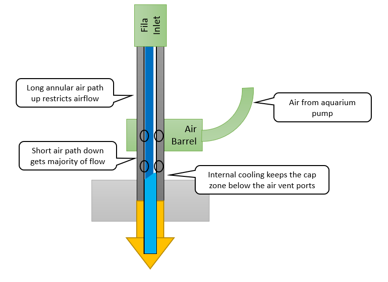
Ryan Carlyle
Jan 12, 2021, 4:07:16 PM1/12/21
to 3DP Ideas
WW, I see your point, but I'm wondering if we might actually reduce resistance this way by eliminating one of the air layers. The primary resistance to heat flux in a computer chip system (aside from internal chip packaging stuff you can't do much about) is the stagnant boundary layer air film between the hot surface and the forced-convection air. Air film boundary layers are a bitch for heat transfer. So a chip heatsink makes the highly-insulating air-film part of the heat flux equation have as much surface area as possible.
.PNG?part=0.1&view=1)
For filament inside a typical hot end, we have TWO stagnant air films -- one between the filament and heat break ID, and another one between the heatsink and forced convection air. (We've been debating on and off for years about whether filament-oiling works in part by replacing the insulating air film with a conductive oil film.)
So we ALREADY have to shed heat from the filament to the air in current hot end designs, unless you have an unreasonably tight fit or you oil the filament. And that heat has to move through the steel heat break wall, M6/M7 thread interface, and then the heatsink before it can actually be removed effectively by air. Thankfully, the upward heat flux load through the filament itself is really small (I haven't run the numbers in a long time but I recall like a fraction of a watt) unless you have excessive retraction distance or something else actively dragging hot filament up into the cold zone.
You'll have more heat flux up the heat break throat metal walls in a typical hot end design (simply because stainless steel is ~100x higher thermal conductivity than plastic) and that heat can be removed any way you want. Or something like a nonstick ceramic spacer with air vent holes could be used.
On Tuesday, January 12, 2021 at 2:39:27 PM UTC-6 whosaw...@gmail.com wrote:

tray
Jan 16, 2021, 11:47:50 AM1/16/21
to 3DP Ideas
> After all, there's a reason
heatsinks are used on chips rather than just blowing air across them.
It's difficult to efficiently couple a heat sink to moving filament. For CPUs, they use a very flat surface and clamping to create a very small gap, which is bridged with a very thin coat of heat sink compound.Whosawhatsis
Jan 16, 2021, 3:57:05 PM1/16/21
to 3DP Ideas, tray
It's relatively easy if you have a thermally conductive fluid as an interface. Once the filament melts, it serves this purpose. Above the melt zone, there is usually air, which is pretty insulate. Once of the theories I've heard about adding oil to filament is that (in addition, of course, to acting as a lubricant) it pools above the melt zone and conducts heat between the filament and the cooler tube walls above the thermal transition zone.
There is, of course, a question of whether you actually need conduction between the cool filament and the walls. Once the filament melts, you definitely want conduction between the heatsink and any melted filament that gets above the thermal transition zone, but of course, melted filament is a fluid, and will conform itself to the walls (at least if there's any extrusion pressure behind it), creating good thermal contact. Between the points where the filament is at room temperature and where it turns into a fluid, how important is the thermal contact?
There is, of course, a question of whether you actually need conduction between the cool filament and the walls. Once the filament melts, you definitely want conduction between the heatsink and any melted filament that gets above the thermal transition zone, but of course, melted filament is a fluid, and will conform itself to the walls (at least if there's any extrusion pressure behind it), creating good thermal contact. Between the points where the filament is at room temperature and where it turns into a fluid, how important is the thermal contact?
To view this discussion on the web visit https://groups.google.com/d/msgid/3dp-ideas/818828be-5a85-44fe-af42-c052a555fc87n%40googlegroups.com.
tray
Jan 17, 2021, 10:44:22 AM1/17/21
to 3DP Ideas
So what you're describing is the plug that forms. The OP, I think, is talking about cooling above that region.
The cold region loses heat as filament is pushed into the plug, gains heat by conduction up from the plug, and gets little bursts of heat from retractions. Integrate those at different print speeds, and you get the power you're trying to transfer to the barrel.
Polymer filament has a long transition from solid to liquid, when it's, er, in a plastic state, losing rigidity and viscosity.
For fast printing, you'd want to minimize the amount of heat it has to absorb downstream, so I don't think you want your filament in the cold zone at room temperature, you want it just cool enough not to slump. Or really, not slump after a retraction. Although, I don't know what the dynamics of what happens at the plug during extrusion, at retraction, or when recovering from retraction. Is the plug a 3D eddy? Does the plug distort on retraction, does the colder filament simply pull back out of the plug, or does the plug shift in the barrel?
Seems like there'd be a research topic for some university type - mix some small metal particles into filament and do real time CAT scans of the plug under those conditions. A lower tech route would be to push a two-colored splice part way through the plug, let it cool, do a cold pull it, and split the plug in half lengthwise to look at it. Do that dozens of times for a slightly longer extrusion, and you could get a stop-motion animation of what's going on.
Ryan Carlyle
Feb 2, 2021, 4:58:08 PM2/2/21
to 3DP Ideas
Right, so, I think Tray is reading me correctly on keeping filament solid above the highly-sheared semi-melt region where pressure is contained (or "cap zone" in old Stratasys patent terminology). Heat creep jams happen when the filament gets hot enough in the cold zone to soften (insulated by the air gap to the walls) and then when pushed, it mashes into contact with the walls, which significantly increases the heat-shedding rate, solidifying to a solid plug. Any cause of filament getting mushy inside a zone with cool enough walls to resolidify it can potentially cause a heat creep jam.
High extrusion rate continuously pushes fresh, cool filament into the hot end, faster than heat conducts up the filament. Slow average extrusion rate allows heat to conduct up the filament. Retraction actively churns the filament and pulls warm material from the semi-melt zone up into the cold zone.
So it really all comes down to filament being kept from getting soft in the cold zone. Any way you do that should address heat creep jams.
Reply all
Reply to author
Forward
0 new messages