WHO'S GOT GPSDO?
353 views
Skip to first unread message

Pamela J. Filicky
Jun 2, 2013, 8:45:11 PM6/2/13
to 2-mete...@googlegroups.com
Hello All - It appears KC6GKE in Taft is now GPSDO and Carol/KP4MD is the most stable as I have seen in awhile..
So who are the new stations with the GPSDO?
Steve/N6KOG

Glenn Elmore
Jun 2, 2013, 8:49:22 PM6/2/13
to 2-mete...@googlegroups.com
Nobody new yet besides Steven.
GPS10P/IC7000 version about ready to go to WA6M and KI6STW. It's been a pain because screwy master oscillator frequency forced big divide numbers and low loop gain. Bob's IC7000 now been running fine with it so maybe this week?
Carol's GPS10V/XV144 is the 5th one and probably still a week or two out but she's been working with fan directions and insulation. At the rate she's going, she may not need anything to reduce drift! :-)
Glenn n6gn
--
You received this message because you are subscribed to the Google Groups "2 Meter WSPR" group.
To unsubscribe from this group and stop receiving emails from it, send an email to 2-meter-wspr...@googlegroups.com.
To post to this group, send email to 2-mete...@googlegroups.com.
Visit this group at http://groups.google.com/group/2-meter-wspr?hl=en.
For more options, visit https://groups.google.com/groups/opt_out.
n6gn
Jun 11, 2013, 10:02:00 PM6/11/13
to 2-mete...@googlegroups.com
11 June 2013
One more station is now running a GPS10. As of mid-day, KI6STW's IC7000 is now also synchronized to the GPS constellation. The current "frequency plan" is:
Frequency Station Radio stabilization
144.490460 KC6KGE Yaesu FT857 GPS10V
144.490470 KI6STW Icom IC7000 GPS10P
144.490480 WA6M Icom IC7000 GPS10P
144.490490 K6PZB Icom IC741 Prototype GPS10P
144.490500 N6GN Icom IC706 Wenzel GPS/OCXO
144.490520 WW6D Yaesu FT897 GPS10V
With Oakland Airport and its associated air traffic between Kevin and the Sonoma County stations, we are seeing a lot of ACS components. Some of these produce separate spots or modify 'groundwave' spots such that WSPR reports frequency differently. Since all stations are both stable and accurate, probably within .5 Hz soundcard accuracy, any drift reported or deviation from nominal frequency has probably been caused by the ACS component.
It does seem that there may be a few tenths-of-Hz error or difference between transmit and receive tones on some sound cards. As noted before, recent builds of WSPR-X seem to have a 2 Hz transmit tone error.
Glenn n6gn

Line Printer
Jun 18, 2013, 12:02:30 PM6/18/13
to n6gn, 2-mete...@googlegroups.com
On Tue, 11 Jun 2013, n6gn wrote:
> One more station is now running a GPS10. As of mid-day, KI6STW's IC7000 is now also synchronized to the GPS constellation.ᅵ
I found that the GPSDO device reveals how useful it can be even in HF use.
I used my IC-7000 with the GPS10P running WSPR on 20 meters yesterday and
examination of the signals I spotted showed that these same signals were
spotted by other WSPR stations at different frequencies.
Based on what I saw, K5XL appears to have a GPS synched WSPR station and
transmitting on 14.097150 MHz. Comparing all the spots of K5XL for each
time period shows a variety reported frequencies.
my spots for K5XL:
130617 1904 24 -6 0.3 14.097150 K5XL EM12 33 0 1 0
130617 1914 19 -13 0.3 14.097150 K5XL EM12 33 0 1 0
130617 1924 19 -13 0.2 14.097150 K5XL EM12 33 0 1 0
130617 1936 14 -17 0.3 14.097151 K5XL EM12 33 0 1 0
GPS can be fun!
Kevin Martinez
KI6STW
--
------------------------------------------------------------------------
Line Printer System | HODIE NATUS EST RADICI FRATER
lps at rahul 'dot' net | 645/6180 BOS/BCE
------------------------------------------------------------------------

KP4MD
Jun 29, 2013, 10:29:45 PM6/29/13
to 2-mete...@googlegroups.com
Effective 29 June 2013 at 2330 UTC KP4MD in Citrus Heights, CA is now GPS disciplined on 144.490510 MHz
144.490460 KC6KGE Yaesu FT857 GPS10V
144.490470 KI6STW Icom IC7000 GPS10P
144.490480 WA6M Icom IC7000 GPS10P
144.490490 K6PZB Icom IC741 Prototype GPS10P
144.490500 N6GN Icom IC706 Wenzel GPS/OCXO
144.490510 KP4MD Flex-1500/Elecraft XV144 GPS10V
144.490520 WW6D Yaesu FT897 GPS10V
29 June 2013 - GPS active antenna has a clear view of the sky, magnetically attached to a steel lumber tie plate on an awning upright.

29 June 2013 - The GPS10V was turned on today and is putting out signals on 116 MHz and 10 MHz.
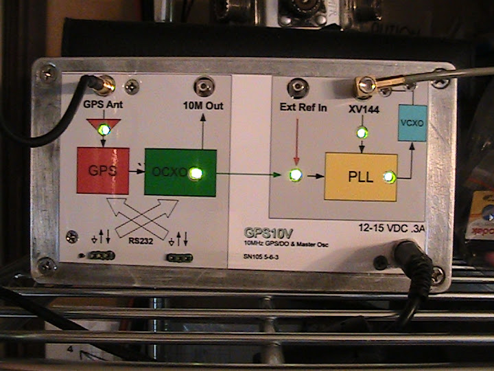
I connected a length of RG-174/U 50 ohm miniature coaxial cable to unused J8 for 116 MHz reference signal from the GPS10V.

Elecraft XV144 Transverter modification for GPS frequency reference.
The 47Ω resistor suppresses the 116 MHz crystal oscillations and Q1 functions to amplify the external 116 MHz reference signal.

The Elecraft XV144 transverter GPS reference modification.
The .01 μF capacitor and 47 Ω resistor are soldered across R5 and the RG-174/U cable connected across the 47 Ω resistor.


n6gn
Jun 30, 2013, 12:18:46 AM6/30/13
to 2-mete...@googlegroups.com
Congratulations Carol!
Your modification looks great and it appears that the trick worked. The 47 ohm load prevents the native crystal from oscillating while also terminating the drive from the GPS10V. I've temporarily turned the N6GN antenna to 90 degrees from 140 in order to capture a few stronger spots from you and it appears that everything is as it should be, to the degree that I can detect. Your traces look straight and everyone seems to be spotting you right on 144.490510. Here is a recent capture showing KP4MD and KI6STW with a lot of ACS but otherwise unremarkable.
![]() The corresponding spot is here
The corresponding spot is here ![]()
I don't know if you managed to get the Flex 10m IF radio to use the 10 MHz GPSDO reference or not. It seems like there was ~ 1 Hz error on the first spots but it can be a bit hard to sort our errors this small with sound cards, IF radio and transverter and ACS all as potential error contributors.
Even if there is a residual few-tenths HZ error among us due to our stations in this way, I think it is pretty safe to assume that none of us is drifting significantly in a 2 minute WSPR interval. This lets us be confident that if we see 'drift' it's actually path-induced. We are probably also all aware by now that significant ACS in conjunction with a non-ACS 'non-drifting' component will sometimes be reported by WSPR as drift. It gets a bit confused sometimes when there are crossing signals.
Glad to have all of us on!
Glenn n6gn
Your modification looks great and it appears that the trick worked. The 47 ohm load prevents the native crystal from oscillating while also terminating the drive from the GPS10V. I've temporarily turned the N6GN antenna to 90 degrees from 140 in order to capture a few stronger spots from you and it appears that everything is as it should be, to the degree that I can detect. Your traces look straight and everyone seems to be spotting you right on 144.490510. Here is a recent capture showing KP4MD and KI6STW with a lot of ACS but otherwise unremarkable.
I don't know if you managed to get the Flex 10m IF radio to use the 10 MHz GPSDO reference or not. It seems like there was ~ 1 Hz error on the first spots but it can be a bit hard to sort our errors this small with sound cards, IF radio and transverter and ACS all as potential error contributors.
Even if there is a residual few-tenths HZ error among us due to our stations in this way, I think it is pretty safe to assume that none of us is drifting significantly in a 2 minute WSPR interval. This lets us be confident that if we see 'drift' it's actually path-induced. We are probably also all aware by now that significant ACS in conjunction with a non-ACS 'non-drifting' component will sometimes be reported by WSPR as drift. It gets a bit confused sometimes when there are crossing signals.
Glad to have all of us on!
Glenn n6gn
KP4MD
Jun 30, 2013, 2:36:55 AM6/30/13
to 2-mete...@googlegroups.com
I did use the Flex-1500 offset to correct the 1 Hz error on spot reports. It should not move much as I've seen the Flex-1500 TCXO to be stable to within 1 Hz per day on HF WSPR.
My first try of the 10 MHz reference with the Flex-1500 gave peculiar results...it looked like all signals on the 144 MHz band were being received together at low level. Then I read in the knowledge base that the FlexRadios require a sine wave reference, not the GPS10 square wave. So an Altoids tin 10 MHz low pass filter is my next project.., something like http://www.vk4adc.com/web/index.php/general-projects/34-frequency-stabilisation/159-lctcxo or http://jwmeng.com/AppNote/AppNote003.html That should be easy with the miniVNA to measure filter response.
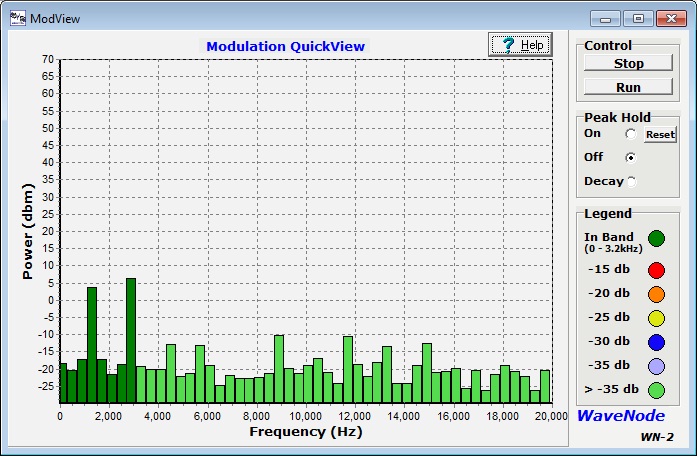
With regard to signal purity, I recall that the WaveNode does provide a demodulator display of transmitted RF. I have always heard a low level tone modulation at 1500 and 3000 Hz superimposed on my WSPR transmissions that I have assumed was a product of mixing with the suppressed carrier and perhaps some nonsinusoidal WSPR program output. The attached displays appear similar to those from before the GPS10 was placed in operation.
Carol, KP4MD
10 MHz External Frequency Reference Input for the FLEX-5000 and...
10 MHz External Frequency Reference Input for the FLEX-5000 and FLEX-1500
Content provided by: FlexRadio Systems Engineering
Both the FLEX-5000 and FLEX-1500 have the facilities for connecting an external precision frequency reference for increased frequency accuracy and stability.
The specifications on the external frequency reference input are as follows:
| System Dependencies | |
| Minimum PowerSDR Version: | N/A |
| Applicable Hardware: | FLEX-5000 & FLEX-1500 |
Content provided by: FlexRadio Systems Engineering
Both the FLEX-5000 and FLEX-1500 have the facilities for connecting an external precision frequency reference for increased frequency accuracy and stability.
The specifications on the external frequency reference input are as follows:
- The input frequency is 10 MHz (sine wave)
- The signal strength range is between 0 and +10 dBm


Glenn Elmore
Jun 30, 2013, 10:39:02 AM6/30/13
to 2-mete...@googlegroups.com
Carol,
I'm a bit surprised about the sine wave requirement. This is not typical
for external 10 MHz inputs on any test equipment I can think of. In
general, fast edges are better not worse. And, beyond that, I can't
think of any real problem that fast edges should produce. I'll be
interested to know if you hear an explanation. You might want to
breadboard a LPF before committing a lot of time in order to be certain
that truly is the problem. However, a few sections of LPF should indeed
knock higher harmonics out and leave you with a very good sinusoid at +5
dBm less the insertion loss of the 50 ohm filter.
I take it that the signal purity question is completely unrelated to the
transverter or GPS10 and that you can hear it on HF too?
I can't immediately think of a source of the 1500/3000 Hz components in
an SDR. Maybe someone else on the Group has an idea. If you had a
conventional radio, poor carrier suppression could, of course, cause
this. The digital equivalent of it could occur but I don't know why it
would. If opposite sideband and carrier terms weren't small, I'd expect
your output to appear to have 1500 and 3000 Hz components when WSPR
transmits with a 1500 Hz tone since that (big) tone would mix with the
carrier (-1500) and LSB (-3000) to generate these products.
Glenn n6gn
KP4MD
Jun 30, 2013, 8:50:24 PM6/30/13
to 2-mete...@googlegroups.com, n6...@sonic.net
The Flex-1500 does work well when tested with a miniVNA generated 10 MHz sine wave reference. Another FlexRadio reflector explained why the Flex-1500 requires a sine wave external reference.
Now that the Elecraft transverter is locked to the GPS disciplined frequency reference, the Flex-1500 internal TCXO has been sufficient to hold the WSPR signal on 144.490510 MHz with 0 Hz drift during transmissions.


> 2) Regarding the 10 MHz reference input: What level does this input like?
> Sine wave/Square wave?
>
It is intended for sine-wave. The 10MHz input goes through a full-wave
rectifier as a frequency doubler. If you use a square wave you get DC out,
not 20MHz. :-) Most good 10MHz references have sine-wave output.
Now that the Elecraft transverter is locked to the GPS disciplined frequency reference, the Flex-1500 internal TCXO has been sufficient to hold the WSPR signal on 144.490510 MHz with 0 Hz drift during transmissions.
I do also hear the weak low level 1500 Hz and 3000 Hz tones when listening to my HF WSPR transmissions on a receiver with the volume turned to maximum. A likely explanation would be heterodyne products with the very weak level suppressed carrier and lower sideband.
Here is the graphic comparison of frequency stability and drift of the Elecraft XV144 transverter before and after the installation of the GPS10 frequency reference.
Carol, KP4MD
KP4MD
Jul 4, 2013, 8:54:45 AM7/4/13
to 2-mete...@googlegroups.com, n6...@sonic.net
Here is G3RJV's design for a cheap and easy 10 MHz low pass filter that requires three T50-6 cores, two 270 pF and two 560 pF capacitors
Carol, KP4MD

On Sunday, June 30, 2013 10:39:02 AM UTC-4, n6gn wrote:
On Sunday, June 30, 2013 10:39:02 AM UTC-4, n6gn wrote:
...You might want to breadboard a LPF before committing a lot of time in order to be certain that truly is the problem. However, a few sections of LPF should indeed knock higher harmonics out and leave you with a very good sinusoid at +5
dBm less the insertion loss of the 50 ohm filter.
,,,
Glenn n6gn
Glenn Elmore
Jul 4, 2013, 12:20:28 PM7/4/13
to 2-mete...@googlegroups.com
I'm sure the multi-element filter would work fine but it's a bit
overkill, I think. If Flex uses a full wave bridge to double the 10
MHz, all it really needs to assure some 20 MHz signal is input that
isn't as perfectly square and 50% duty cycle like the output of the
GPS10 - which is really quite good, it's a textbook square wave on
my 350 MHz Tek scope.
I don't know why Flex didn't just do this for us, they could have made their radio work with either sine or square sources with the addition of two parts, probably no more than a few cents. This actually would conform much better to most test equipment that has 10 MHz input/outputs. Here's what QUCs says two parts will do:

That should give a fairly decent sine wave and is easier, smaller and cheaper. I modeled the self-resonance of a typical Digikey Part (DN7690-ND) with a parallel C, I may have missed in value slightly but it doesn't make much difference in performance.
This all *does* assume that Flex has a 50 ohm input impedance. I can't find that they specify sine in the user manual and nothing other than 0-15 dBm. The above circuit would do that from the GPS10 and could have fit inside the Flex. I suspect a designer at Flex didn't notice the problem until it was too late...
Glenn n6gn
I don't know why Flex didn't just do this for us, they could have made their radio work with either sine or square sources with the addition of two parts, probably no more than a few cents. This actually would conform much better to most test equipment that has 10 MHz input/outputs. Here's what QUCs says two parts will do:
That should give a fairly decent sine wave and is easier, smaller and cheaper. I modeled the self-resonance of a typical Digikey Part (DN7690-ND) with a parallel C, I may have missed in value slightly but it doesn't make much difference in performance.
This all *does* assume that Flex has a 50 ohm input impedance. I can't find that they specify sine in the user manual and nothing other than 0-15 dBm. The above circuit would do that from the GPS10 and could have fit inside the Flex. I suspect a designer at Flex didn't notice the problem until it was too late...
Glenn n6gn

Steven Hess
Jul 4, 2013, 12:24:35 PM7/4/13
to 2-mete...@googlegroups.com
I think Flex really tried to save pennies on the Flex-1500. There it a lot they left out. Liker sensors for wattage out and SWR. They had a price point and designed to that.
--
____________
Apply appropriate technology. Use what works without prejudice.
Steven L Hess ARS KC6KGE DM05gd22
Google Voice 661 769 6201 +SMS
openSUSE Linux 12.2 KDE 4.8.5
Known as FlameBait and The Sock Puppet of Doom.
--
You received this message because you are subscribed to the Google Groups "2 Meter WSPR" group.
To unsubscribe from this group and stop receiving emails from it, send an email to 2-meter-wspr...@googlegroups.com.
To post to this group, send email to 2-mete...@googlegroups.com.
Visit this group at http://groups.google.com/group/2-meter-wspr.
____________
Apply appropriate technology. Use what works without prejudice.
Steven L Hess ARS KC6KGE DM05gd22
Google Voice 661 769 6201 +SMS
openSUSE Linux 12.2 KDE 4.8.5
Known as FlameBait and The Sock Puppet of Doom.
KP4MD
Jul 19, 2013, 9:16:47 PM7/19/13
to
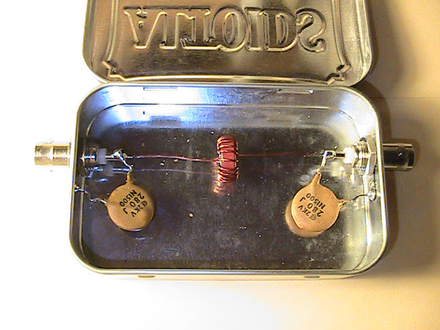
Today at 0330 UTC I added a 3 pole low pass filter on the 10 MHz output of the GPS10V. Now both the FLEX-1500 and the Elecraft XV144 are locked to the GPS frequency reference.


- The GPS10V 10 MHz square wave frequency reference did not work with the Flex 1500 since the Flex 1500 reference input uses a bridge rectifier as a frequency doubler and requires a sine wave source. Since a square wave consists of a sine wave at the fundamental frequency combined with all its odd harmonics, a low pass filter will convert a square wave to a sine wave. I used RFSim99 to design this 3 pole Butterworth low pass filter.
- The RFSim99 simulation model yielded a frequency response curve with 1.7 dB loss at 10 MHz and 30 dB attenuation at the 30 MHz third harmonic.
- The Low Pass Filter was built into an Altoids box. The 1.4 µH inductor is 17 turns of 22 AWG magnet wire on a T50-2 toroid core.
- The filter's actual frequency response measured with a MiniVNA Pro corresponds with that predicted by the RFSim99 model, and the Flex 1500 now works with the GPS10V frequency reference.
Steven Hess
Jul 24, 2013, 7:40:03 PM7/24/13
to 2-mete...@googlegroups.com
Kind of wondering why I spot Kevin at 144.490469 so often then at 144.490470? IS this ACS?
--
____________
Apply appropriate technology. Use what works without prejudice.
Steven L Hess ARS KC6KGE DM05gd22
Google Voice 661 769 6201 +SMS
I'd think I'd expect more of a difference in frequency wouldn't I?
On Thu, Jul 18, 2013 at 9:37 PM, KP4MD <kp...@cfmilazzo.com> wrote:
Today at 0330 UTC I added a 3 pole low pass filter on the 10 MHz output of the GPS10V. Now both the FLEX-1500 and the Elecraft XV144 are locked to the GPS frequency reference.
- RFSim99 calculated these values for a 3 pole Butterworth Low Pass Filter to convert the GPS10V 10 MHz square wave reference signal to a sine wave.
- RFSim99 simulated this frequency response curve for the low pass filter.
- The Low Pass Filter was built into an Altoids box. The 1.4 µH inductor is 17 turns of 22 AWG magnet wire on a T50-2 toroid core.
- Actual Low Pass Filter frequency response measured with MiniVNA Pro.
On Thursday, July 4, 2013 12:20:28 PM UTC-4, n6gn wrote:
I'm sure the multi-element filter would work fine but it's a bit overkill, I think. If Flex uses a full wave bridge to double the 10 MHz, all it really needs to assure some 20 MHz signal is input that isn't as perfectly square and 50% duty cycle like the output of the GPS10 - which is really quite good, it's a textbook square wave on my 350 MHz Tek scope.
--
You received this message because you are subscribed to the Google Groups "2 Meter WSPR" group.
To unsubscribe from this group and stop receiving emails from it, send an email to 2-meter-wspr...@googlegroups.com.
To post to this group, send email to 2-mete...@googlegroups.com.
Visit this group at http://groups.google.com/group/2-meter-wspr.
For more options, visit https://groups.google.com/groups/opt_out.
____________
Apply appropriate technology. Use what works without prejudice.
Steven L Hess ARS KC6KGE DM05gd22
Google Voice 661 769 6201 +SMS
openSUSE Linux 12.3 KDE
Glenn Elmore
Jul 24, 2013, 7:58:30 PM7/24/13
to 2-mete...@googlegroups.com
I think that is to be expected of long ACS paths. If I ever get around
to graphically presenting the equations, we should be better able to
appreciate why.
Large frequency difference generally means greater rate of change of
path length. For this to happen, the aircraft need is more likely to be
moving at right angles to the path between stations. For our paths, this
is a rare vector (not LA/SF) and the aircraft gets out of position where
it is useful for scattering sooner.
Maybe there's a better explanation.
Sometimes, but rarely we see large offsets that are decodable. I'd like
to know what flight number these correspond to but I haven't yet made
the connection.
Glenn n6gn
Steven Hess
Jul 24, 2013, 8:11:49 PM7/24/13
to 2-mete...@googlegroups.com
Ah. I understand that explanation.
I wonder if there is a correspondence also in direction of travel of the aircraft as well in relation to rising or falling frequency over longer paths too?
--
You received this message because you are subscribed to the Google Groups "2 Meter WSPR" group.
To unsubscribe from this group and stop receiving emails from it, send an email to 2-meter-wspr+unsubscribe@googlegroups.com.
To post to this group, send email to 2-mete...@googlegroups.com.
Visit this group at http://groups.google.com/group/2-meter-wspr.
For more options, visit https://groups.google.com/groups/opt_out.
Glenn Elmore
Jul 24, 2013, 8:24:30 PM7/24/13
to 2-mete...@googlegroups.com
I'm sure there is. Even an aircraft flying directly between endpoints
should not produce zero Doppler shift since the direct path between
endpoints, that would have counteracting to and from Doppler components,
is actually through the earth. At midpoint between the stations (perhaps
the best location for us to see strong reflections, there may still be
no shift but as the aircraft gets to one end and passes over a station
there will be no shift on the path to the close station but lots of
shift from the more distant one. I think the net effect is that offset
increases as the aircraft gets near the ends -where we may not have the
strongest spots.
In addition to the above, there's the issue of antenna pattern and take
off angle. Our main lobes are probably not down at zero degrees where
the aircraft are but pushed up quite a bit by the ground. Even with a
moderately high tower at 2m, the center of gain is probably quite a few
degrees up. I measured sun noise on 2m and 432 one time as the sun rose
and until it got quite late in the morning. With 30' sort of antenna
heights I think I remember seeing 20-30 degree elevation to the peak of
the main lobe - with the greater amount on 2m where the antenna was
lower in terms of wavelength.
It's an issue of the complete aircraft vector, direction and speed, as
well as endpoint and aircraft position.
I can't picture it in my head and I think it a perfect task for a
computer with some graphics!
I wrote out what I think are the equations - I need to go back and see
if I still think I did it right - but I haven't gotten around to writing
code to solve them given user-entered data and graphically display the
results. Maybe this winter when Hawaii isn't coming in strong to
California. KH6HME beacon hit S5 here this morning on the 25', 4 element
WSPR antenna looking through the trees! :-)
Glenn
KP4MD
Oct 6, 2013, 3:01:29 AM10/6/13
to 2-mete...@googlegroups.com, n6...@sonic.net
Upon further investigation using my $20 RTL-SDR USB dongle receiver, the weak low level 1500 and 3000 Hz tones appear to be heterodyne beats with the suppressed carrier and lower sideband. Here are some SDRSharp screen captures I took today:
Carol, KP4MD


On Sunday, June 30, 2013 5:50:24 PM UTC-7, KP4MD wrote:
Spectrum analysis of 2 meter WSPR signal from FlexRadio 1500, Elecraft XV144 Transverter and Mirage B2518G Linear Amplifier.
The first photo was taken at 55 watts output with amplifier on, and the second photo at 5.1 watts output with the amplifier turned off.
All signals appear to decrease about 10 dB with the amplifier turned off.
The large peak on the right is the WSPR transmission on the upper sideband at 144.4905 MHz.The central peak is the suppressed carrier and the left peak is the suppressed lower sideband.
The unwanted signals appear to be suppressed about 40 dB from the upper sideband WSPR signal.
The unwanted signals appear to be suppressed about 40 dB from the upper sideband WSPR signal.
This is a relative measurement using SDRSharp software with an uncalibrated $20 RTL-SDR USB DVB-T dongle receiver.
FlexRadio 1500 specifications are: SSB Carrier Suppression : At least 55 dB below peak output.
Undesired Sideband Suppression : At least 55 dB below peak output.
Undesired Sideband Suppression : At least 55 dB below peak output.
Some non-linearity in the transverter and amplifier may affect the degree of suppression measured in the amplifier output.
On Sunday, June 30, 2013 5:50:24 PM UTC-7, KP4MD wrote:
...I do also hear the weak low level 1500 Hz and 3000 Hz tones when listening to my HF WSPR transmissions on a receiver with the volume turned to maximum. A likely explanation would be heterodyne products with the very weak level suppressed carrier and lower sideband.Carol, KP4MD
On Sunday, June 30, 2013 7:39:02 AM UTC-7, n6gn wrote:
Carol,
....I take it that the signal purity question is completely unrelated to the transverter or GPS10 and that you can hear it on HF too? I can't immediately think of a source of the 1500/3000 Hz components in
Reply all
Reply to author
Forward
0 new messages