SLC Free Latest Build Notes and Tips
251 views
Skip to first unread message

Alan To
Oct 9, 2014, 4:32:51 PM10/9/14
to
Hi,
I will put the latest notes and tips on Building SLC Free here.
May 2 2014:
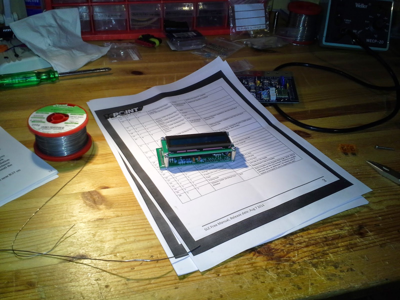
The beige Molex connectors are crap, I regret using them. You should solder the sensor and the power cables directly to the PCB.
Issues with LCD clearance and the electrolytic capacitors:
- When you solder the electrolytic capacitors, make sure they are flush to the board. I recommend soldering just 1 leg, then push the capacitor down while your iron is heating the the leg that is soldered.
- The electrolytic capacitors may touch the black metal tabs on the back of the LCD, you just need to twist the metal tabs a little bit and it will be clear of the capacitors.
- It is a good idea to put some tape on the top of the electrolytic capacitors so there is no chance it makes contact with components on the back of the LCD.
Oct 9 2014:
New kits no longer come with the molex connectors, the cables should be soldered to the PCB
New kits have a taller standoffs so no more clearance issues, you will still have to twist the black metal tabs on the back of the lcd so that it does not interfere with the electrolytic capacitors, tape ontop the electrolytic capacitors is still a good idea.
New kits have a 750 ohm resistor for R15, on the PCB R15's value is labelled as "1.2k" but you should use 750 ohms for R15. If the contrast is too dark then additional 1k and 1.2k resistors are in the kit for you to try out to set the contrast level.

tomas...@gmail.com
May 10, 2014, 3:47:51 AM5/10/14
to 14Po...@googlegroups.com
Hello Alan,
I just received my kits in good order. Thank you.
Would it be possible to post some pictures of the tips ?
I am not good at electronics (even don't know the different type of capacitors).
Regards,
Tomas
I just received my kits in good order. Thank you.
Would it be possible to post some pictures of the tips ?
I am not good at electronics (even don't know the different type of capacitors).
Regards,
Tomas

Antti Karttunen
Oct 9, 2014, 1:58:12 PM10/9/14
to 14Po...@googlegroups.com


Alan To
Oct 11, 2014, 1:53:17 PM10/11/14
to 14Po...@googlegroups.com
Nice build
Message has been deleted
Antti Karttunen
Nov 6, 2014, 9:23:51 AM11/6/14
to 14Po...@googlegroups.com


SuperdaveMotorsports
Nov 7, 2014, 4:21:15 PM11/7/14
to 14Po...@googlegroups.com
How long did it take to get your kit once you ordered it?
SuperdaveMotorsports
SuperdaveMotorsports

matthew lorenzi de fretes
Jun 23, 2017, 8:51:00 AM6/23/17
to 14Point7
hei any one can help me to make lcd display shows afr ????

Warwick Harris
Jun 24, 2017, 2:40:49 AM6/24/17
to 14Point7
Have you tried anything yet?
Maybe you could post what you have done and we could help.
Reply all
Reply to author
Forward
Message has been deleted
Message has been deleted
0 new messages