ICE Modeling workshop : The Capping Tool

Guillaume Laforge

Guillaume Laforge

Eric Thivierge
--------------------------------------------
Eric Thivierge
Technical Director
http://www.ethivierge.com
Guillaume Laforge
Fabricio Chamon
damn, this makes me a 3dmax and you a Softimage...not fair
ok, hands on again. One question: are you doing it with no
repeat/while nodes at all ? I've managed to build a very rough extrude
along curve compound without the "evil" nodes, but in our case, I
couldn't find a way to search for neighbours border vertices only with
arrays and intrinsic attributes...
Fabricio Chamon
Guillaume Laforge
Guillaume Laforge
Guillaume Laforge

Eugen Sares
thanks for doing this ICE workshop, it's so great to see Softimage getting
enhancements in the modelling department!
Are you planning to "release" all the things that get done here in some
repository, for everyone's benefit?
For the mere "users"...
For another workshop, may I suggest a tool which would really make a lot
of sense having: "Power Extrude".
An Operator that extrudes Curves (with Subcurves) along other Curves (also
with Subcurves), with correct corner mitering.
Know the 3ds max "Sweep" Modifier? This kind of thing.
Extrusions, or their shortcomings in SI, have been discussed many many
times here already. See Kim Aldis' TinyExtrude...
Now with ICE Modelling, time has come to catch up.
Is it theoretically possible, since ICE Modelling does not have NURBS
support yet?
We have the Compounds "Create Extrusion Along Strands", but not "Create
Extrusion Along Curve"...
Yet there's "Create Strand from Curves". Is this the way to go?
I'm thinking about doing it myself, but the learning curve looks a bit
steep at the moment, and a lot of people have a big headstart already.
Let's see...
First step could be an Op that simply creates Tubes = Extrude with only
circular cross section.
In 3ds max, Splines have a checkbox "Renderable" for this. Params are:
number of subdivisions in the cross-section, along the path, and rotation.
What say you?
By the way: my CurveTools Addon is finished. Going to release it after I'm
done with a small Tutorial Video.
Yet Curves alone are not much worth without the option to extrude
them/convert them to polys, that's why I'm asking.
All the best,
Eugen

Andreas Bystrom
maybe not the most useful tool but it would make a good workshop too I think
Andreas Byström
Lighting TD - Weta Digital
Fabricio Chamon
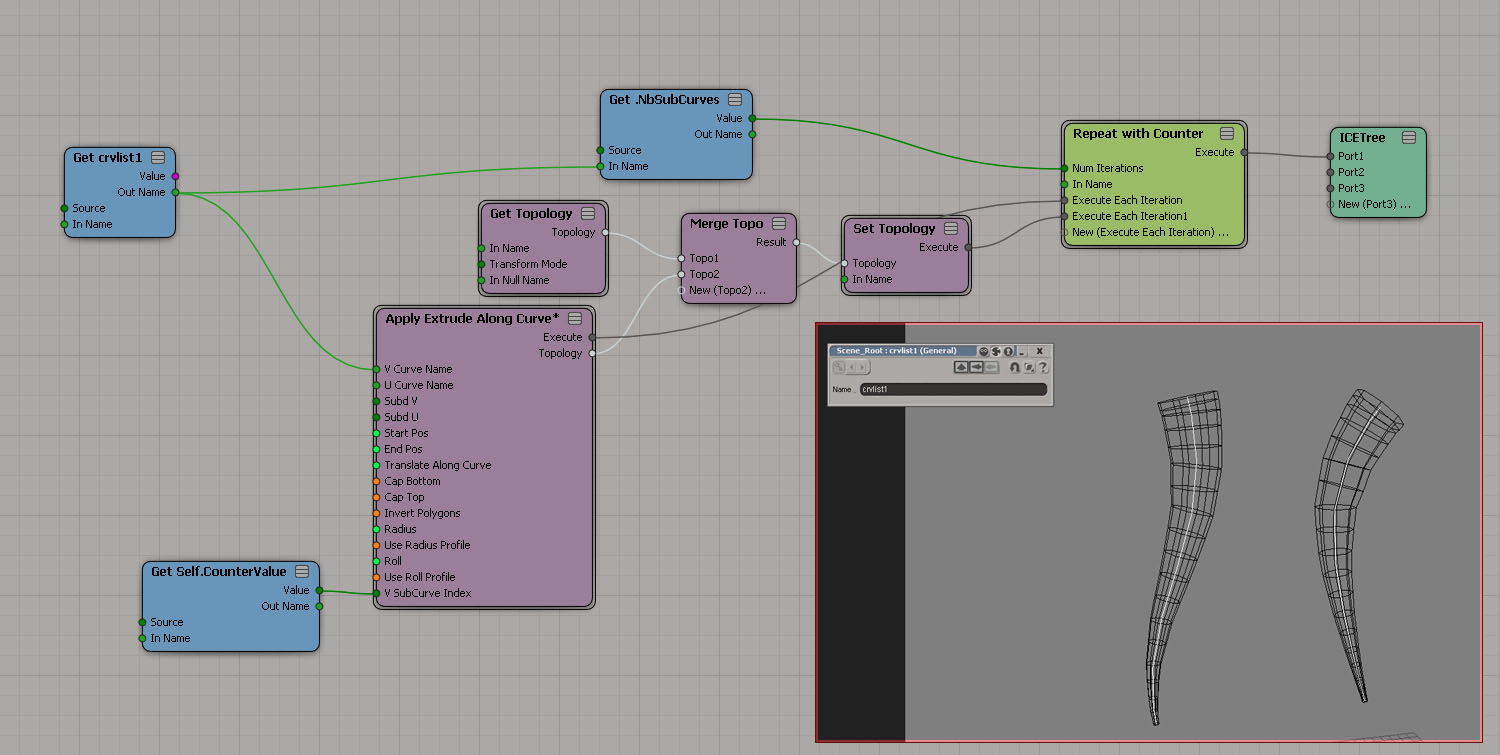
I'm currently in the process of developing an extrude along curve
compound. For now it features:
- number of subd V
- number of subd U (cross sections)
- default circular cross sections if no U shape curve is specified
- V Curve Start Pos.
- V Curve End Pos.
- translate along curve (like on "deform along curve" factory op)
- Cap Top
- Cap Bottom
- Invert Polygons
- Radius
- modulate radius by fcurve profile (along curve)
- Roll
- modulate roll by fcurve profile (along curve)
- Constraint extruded mesh to V Curve
..and this is what I'm aiming to do (or what is still missing):
- subdivision type (Per Span/Absolute)
- Spiral Displace Along Curve (control for radius offset/frequency)
- UV generation/modification
Tomorrow I'm going to post a video + the scene file (which I forgot at
my home pc), so that we can discuss and improve it.
I like the idea o having support for subcurves, will try to implement
it. Also let me know what else features you'd like to see in a tool
like this.
This has been a nice experience to me (regarding ice modeling). So
i'll try to share as much as possible from what I've learned so far.
And about the workshop, I'm all for it!
Fabricio
Fabricio Chamon
is long overdue :P
maybe not the most useful tool but it would make a good workshop too I think"
agreed!
Eugen Sares
But pretty please: don't forget the support for multiple Subcurves, for
both path and cross section!
Can't be more than two additional loops for all Subcurves.
It would simplify a lot of modelling situations - you don't have to mess
with 100 separate objects if you keep Curves together in one CurveList.
I'm halfway finished with that tutorial video for my CurveTool addon,
which will be a nice companion to your plugin when it comes to curve based
modelling.
Ah yes: new Revolution tools would also be cool, with Subcurve support...
Just in case you look for another challenge. =}
Best,
Eugen
On Wed, 04 May 2011 17:10:41 +0200, Fabricio Chamon <xsim...@gmail.com>
wrote:
Guillaume Laforge
>We have the Compounds "Create Extrusion Along Strands", but not "Create Extrusion Along Curve"...
>Yet there's "Create Strand from Curves". Is this the way to go?
Fabricio Chamon
As Guillaume said, the curve normal is not always good, so sometimes
you get a flipped crosssection range. In the compound I'm subtracting
pointpositions from the previous point, then using direction to
rotation to rotate my crosssections *before* positioning then on the
path curve... I think this could avoid the flips, but I'm not 100%
sure.
as far as performance I managed to avoid any repeat/while nodes. Let's
see if I can stay like this till the final version of the compound! =)
talking about subcurves, it's using UV to location to position the
crosssections on the path curve, so it may be possible to switch
between path subcurves already (didn't tested yet). But it would
require a complete revision to contemple all subcurves at once.
As it all started as an exercise, I didn't look at any of the factory
compounds. So please (Guillaume) let me know of any optimization I'm
missing.
Guillaume Laforge
Mirko Jankovic
way out of my CIe reach, no time to tinker there as well as many others I'm sure. :(
But can't wait for a nice compilation like Power ICE Modeling tools.. PIMT !!! (well we can get better name that is for sure :))) You amazing guys make tools the rest of us will think of a name for power modeling toolset :)
cheers
Sebastian Kowalski
i hope i have some time left this week to catch up.
sebastian
Fabricio Chamon
Performance-wise it looses a bit because of the "repeat" and the
"merge topo" nodes. But for now it serves as s quick workaround.
modifications:
- exposing the uv to location subcurve index
- instead of setting topology inside the compound it outputs the topology itself
Guillaume Laforge

Christopher Tedin
Szabolcs Matefy
produced my Melena :)
Stefan Kubicek
--
-------------------------------------------
Stefan Kubicek Co-founder
-------------------------------------------
keyvis digital imagery
1050 Vienna Wehrgasse 9 Austria
Phone: +43/699/12614231
--- www.keyvis.at ste...@keyvis.at ---
-- This email and its attachments are
--confidential and for the recipient only--
Fabricio Chamon
current topo in an array. Then after the repeat, use the Merge Topo
Array and set the topology"
Indeed. Thanks for the tip.
@Szabolcs: nice idea. It shouldn't be too difficult to use pointcloud
strands as well. Let me see here...

Guillaume Laforge
-----Original Message-----
From: softimag...@listproc.autodesk.com [mailto:softimag...@listproc.autodesk.com] On Behalf Of Fabricio Chamon
Sent: Thursday, May 05, 2011 11:10 AM
To: soft...@listproc.autodesk.com
Subject: Re: "Power Extrude"
Fabricio Chamon
Guillaume Laforge
Eugen Sares
One more thing:
if you did not so already -
on sharp corners on the extrusion path, could you possibly please
compensate the cross section width by a factor so that the outlines stay
parallel to the path (= correct corner mitering) ?
factor = 1 / sin( angle(prevSegment, nextSegment)/2 )
This is a very important feature for geometric/architectural modelling,
believe me!
Been hoping for this for ages now...
Thanks so much!!
On Thu, 05 May 2011 17:26:01 +0200, Fabricio Chamon <xsim...@gmail.com>
wrote:
> lol!!! yes
Szabolcs Matefy
example. Unfortunately for some reason melena strands with the ice
compound you mention produce mesh, with each polygon in the center...

Robert Chapman
tried to build this from your screen shot last night, got stuck on
creating 'get last value in vertex array' node figured it might be a
pop from array from the 'cap_vertexarray' but I couldn't seem to get
point location from this without it going red. Also would not know how
to begin to create the 'test double edges' node , but the rest of the
tree , although initially daunting, was fine with constructing from
Fabricio's and yours previous ICE modelling tree examples . there a
whole load of new attributes to learn & pick from now, but Ive not
done much work with arrays yet so its more to do with my rudimentary
logic skills rather than anything wrong with ICE modelling. this is
where the practice is going to help :)
regards,
Rob
Guillaume Laforge
Guillaume Laforge
Fabricio Chamon
position as a tangent basis. So maybe Melena system create the first
strand position on the point position ?"
yes, took me some minutes to figure this out when trying the "create
extrusion along strands" with my strand tree compounds. That's exactly
what I do, create the first strand segment on the same position as my
points. An alternative would be provide the users a "start strand
segment index" option on the compound, so that the meshing starts at a
defined index on the strandpostiion array.
@eugen: I'm already looking into the corner mitering thing. few more
days for an update... =)
Fabricio Chamon
challenge! Willing to see much more coming...
Guillaume Laforge
Guillaume Laforge

Claude Vervoort
Doing ICE modelling is definitely a mind set to acquire (at least for me), especially the fact that you work in a given context. So for example I did not see a simple way from a vertex to get the other connected vertices. The only way I have found to do this is:
- First collect the connected edges (in vertex context, filtering the vertices by vertex id) and get the associated edges
- then in another subtree executing in edge context, filter by the edges just found and get the associated vertices.
Thanks again for setting this up! If interested you can set my commented ICE Tree at: http://claudeonthe.net/images/si/cap_ice_modeling_challenge.jpg One key element missing is to produce the cap in the correct winding order. For that I am not sure.
Anyway time to look at the answer and move on to the next challenge :)
Claude
Guillaume Laforge
Claude Vervoort
BTW when I try to run the plugin here, I have this error:
ERROR : 21000-EDIT-PrivateGetCompoundConstructionMode - Unspecified failure - [line 712 in D:\Program Files\Autodesk\Softimage 2012\Application\DSScripts\operators.vbs]
Application.ApplyICEOp("Cap Borders", "", "", "siUnspecified")
# ERROR : Traceback (most recent call last):
# File "<Script Block 2>", line 35, in CapBorders_Callback
# ICETree = si.ApplyICEOp( "Cap Borders", None, None, C.siUnspecified )
# File "<COMObject XSI.Application>", line 2, in ApplyICEOp
# COM Error: Unspecified error (0x-7fffbffb) - [line 34 in C:\Users\Claude\Autodesk\Softimage_2012\Addons\ICEModelingTools.0.1\Application\Plugins\ICEModelingMenuPlugin.py]
I haven't looked too much into it, don't spend anytime on it but if you have a quick idea about what I should look at, i'll take it.
Claude
Guillaume Laforge
Claude Vervoort
Claude

Stephen Blair
From: softimag...@listproc.autodesk.com [mailto:softimag...@listproc.autodesk.com] On Behalf Of Claude Vervoort
Sent: May-10-11 7:57 AM
To: soft...@listproc.autodesk.com
Subject: Re: ICE Modeling workshop : The Capping Tool
Oh thanks for the pointer, i've played a bit with Python on SI before, but that is my fresh 2012 so maybe I need to update something...
Claude
On Tue, May 10, 2011 at 5:40 AM, Guillaume Laforge <guillaume....@gmail.com<mailto:guillaume....@gmail.com>> wrote:
Hi Claude,
It looks like you don't have python working correctly on your machine. I'm not an expert in this area btw. First thing I would try is to open a Softimage command prompt and run : runonce.bat
If it doesn't help, I'm sure you will find a Softimage Python specialist here to help you :)
Cheers
Guillaume
On Mon, May 9, 2011 at 10:59 PM, Claude Vervoort <claude....@gmail.com<mailto:claude....@gmail.com>> wrote:
I have been on the ICE before but not in the modeling arena though, and not for long enough since I was not aware at all of pointNeighbors (when I think how much time I spent trying to get to those :) ). Thanks for the scene too!
BTW when I try to run the plugin here, I have this error:
ERROR : 21000-EDIT-PrivateGetCompoundConstructionMode - Unspecified failure - [line 712 in D:\Program Files\Autodesk\Softimage 2012\Application\DSScripts\operators.vbs]
Application.ApplyICEOp("Cap Borders", "", "", "siUnspecified")
# ERROR : Traceback (most recent call last):
# File "<Script Block 2>", line 35, in CapBorders_Callback
# ICETree = si.ApplyICEOp( "Cap Borders", None, None, C.siUnspecified )
# File "<COMObject XSI.Application>", line 2, in ApplyICEOp
# COM Error: Unspecified error (0x-7fffbffb) - [line 34 in C:\Users\Claude\Autodesk\Softimage_2012\Addons\ICEModelingTools.0.1\Application\Plugins\ICEModelingMenuPlugin.py]
I haven't looked too much into it, don't spend anytime on it but if you have a quick idea about what I should look at, i'll take it.
Claude
On Mon, May 9, 2011 at 12:30 PM, Guillaume Laforge <guillaume....@gmail.com<mailto:guillaume....@gmail.com>> wrote:
Hi Claude,
Your tree is rather good, and it looks like you are not an ICE beginner :), are you ?
> I think I am due to a oh! moment when I will look at the actual solution!
Well, you will find my solution not so interesting from an educational point of view ;). I thought that this scenario would be a good opportunity to learn how to switch between contexts. But in fact, I found that using the PointNeighbors attribute was the way to do it and so I skipped this part :-/.
> So for example I did not see a simple way from a vertex to get the other connected vertices.
The PointNeighbors attribute do the job for you (finding the point locations connected by an edge to the current point) ;).
But it is always good to know how to do it without this attribute, (and so your comment is really useful) because sometime, we can't deal with point locators to get the data if we are not in per point context. And yes, you are right about the workflow (getting connected edges etc...)
For those interested on how to switch between context here is a sample scene :
http://dl.dropbox.com/u/5533643/Softimage/GetPointNeighbors.scn
The idea is to switch from a per element context to a per object context to store an array of indices. This data can be accessed without problem from all per element contexts.
Cheers,
Guillaume
Stephen Blair
In the ICE Tree viewer, open the Preset Manager and click the Refresh button.
Check that Cap Borders is available in the Preset Manager.
After that, the Cap Borders menu command should work (it wasn't finding the compound).
A restart might fix the problem too, but I didn't try that.
Thanks
guillaume laforge
Addon install won't do a scan of the preset manager, so it explains the pb on the first try
Guillaume Laforge
Sent from my iPhone
> <winmail.dat>
Fabricio Chamon
http://vimeo.com/23859554
new features:
- correct corner mitering (thanks Eugen for providing the formula and idea)
- support for multiple path subcurves (choose subcurve index or use
all subcurves)
- subdV/subdU renamed to Path curve and Profile curve for better readability
- corrected cross section rotations (non-flipping normals) - there was
a bug in the previous version
- constraint to path flag
- split radius and roll along curve controls into "control compounds"
for cleaner/smaller interface
- all main parameters are now array based, which means that
radius/roll/start/end, etc can be controlled per subcurve.
- mesh has a new Self.PathSubcurveIndex variable that can be used to
modulate any extrusion effect (also per subcurve).
roadmap:
- support for multiple profile subcurves
- support for closed curves
compounds are attached. Let me know what you think, bugs, requests..etc.
Also should mention that the correct cross sections rotations were
"stolen"/adapted from Guillaume's Extrusion along strands compound.
(thanks Guillaume)
ps: Eugen, when are you planning to release your curve tools ? I'm
sure it would help me improving the compounds...new ideas, etc
Fabricio Chamon
- support for multiple profile subcurves
- support for closed curves"
...oh and sure...UVs
Christopher Tedin
Eugen Sares
On Tue, 17 May 2011 21:26:32 +0200, Fabricio Chamon <xsim...@gmail.com>
wrote:
> After 2 very busy weeks, I found some time for an update:
First, it's so great so see your Operator evolve! Brilliant job!
Did you release it somewhere? Will you charge something for it?
Need a "beta-tester"... ? ;)
My CurveTools are actually already released, but only on xsiforum.de.
I'd like to do a simple video demo first before I put it on the "mighty"
mailinglist, and I'd also like to finish support for Isopoints in
SplitSubcurves (trickier than in looked).
Got a hint from Alok Gandhi - thanks to him!! - only 2 days ago for that,
and didn't find the time to finish it yet.
Soon!!
Best regards,
Eugen
Eugen Sares
The hour is late...
.ᅵ}
On Wed, 18 May 2011 00:07:58 +0200, Eugen Sares <soft...@keyvis.at>
wrote:
Eugen Sares
here a few suggestions how you to boost "Extrusion along Curve" to the
swiss army knife of all extrusion ops:
- Support for multiple open/closed profile/path Subcurves
- UVs
(like you said)
- Script to apply it comfortably, maybe in menu Model>Create>PolyMesh
(Should ICE modeling ops not reside somewhere under ICE?)
- If no path Curve is connected, the Operator could extrude along an Axis,
with param X/Y/Z to choose.
This would put two Ops in one - no additional "Extrude along Axis" needed
anymore. Very handy!
So if neither a Profile nor a Path is connected, a Cylinder is generated.
- Important: subdivision params should define the subdivs on a Segment
(Curve part between two Knots), not along the whole Curve (both path and
profile)!
In other words, there should always be a subdivision on every Curve Knot.
If the subdiv param is cranked down to 1, Segments become linear.
It's impractical having to adapt the number of path subdivs when the
number of points/knots changes.
The factory "Extrusion along Curve" Op works that way, too, also the
"Hardware display" node of a Curve (degree 2 or 3).
- Experimental: define Material IDs per Curve segment, and give that ID to
the created Polygons (3ds max has this).
That way, it won't be necessary to create Material Clusters on the
polymesh, because Clusters won't update with Curve changes, and the
Material assignment gets messed up.
There's no "Segment" Component in Softimage like in max yet... I wonder if
there a way to store additional information along a Curve that updates
automatically when it changes?
For convenience:
- Mirror Profile across X/Y
- Shift/Translate Profile X/Y
What do you think?
Best,
Eugen
Fabricio Chamon
thanks for the feedback Eugen. Let's see if I can handle all your requests.. =)
already working on an update...
Stefan Kubicek
I no one else wants it and if OK with Fabricio I'd volunteer for creating proper menu entries and a custom command that applies the compound (and ICE Tree if not already present) , sets and connects the required Get Data nodes and inspects the PPG's (as long as Ctrl is not pressed) for a streamlined workflow that is more in line with Softimage's modeling paradigms.
--
-------------------------------------------
Stefan Kubicek Co-founder
-------------------------------------------
keyvis digital imagery
1050 Vienna Wehrgasse 9 Austria
Phone: +43/699/12614231
--- www.keyvis.at ste...@keyvis.at ---
-- This email and its attachments are
--confidential and for the recipient only--
Eugen Sares
You know, this Operator of yours is among the things I always missed in SI
since I switched to Softimage.
The others are:
- better Curve Tools - did my best as an amateur coder to fill some of
those holes.
- a better Renderer for complex GI scenes than mray - Arnold and VRay are
underways.
Not much left to justify using ol' 3ds max shortly... for any job.
On Wed, 18 May 2011 15:19:53 +0200, Fabricio Chamon <xsim...@gmail.com>
wrote:
> I think those are all great improvements!
Fabricio Chamon
thanks Stefan. And feel free to add menu entries/custom commands, in
the end I'll pack everything inside an addon.
Kim Aldis
If your control points aren't evenly spread then the segments in your curve are going to vary considerably in their length as you move along your curve. This is a problem to some degree for resolution but mostly it's a horrible thing to have to deal with when you're texturing.
If you have sharp corners in your curve, segment edges will probably miss the corner points and you'll get horrible detail there. Worse still, if you're animating your curve you'll get nasty animated artefacts as the segment edges kind of travel over the corners.
You can get round this things to some degree by calculating points on a per segment basis, working out how many segments of a particular length you need for each segment. This will be a non integer value so you tweak the length for each segment to make an integer fit. The segments won't be exactly the same length but they'll be close enough not to matter.
Hope this makes sense.
Fabricio Chamon
change the cross sections subdivision method.
I'm considering 3 subdivision types:
- Segment length dependent (the way it is right now)
- Evenly distributed, fixed (equally spread, but does not change
number of cross sections after curve tweaking)
- Evenly distributed, spacing ratio (equally spread, and changes the
number of cross sections in relation to the path curve length)
all three should produce good UVs (first one will have stretching
compensation for the changing segment lengths), with u/v scaling and
independent controls for the capping parts.
Talking about the segment angles, maybe I could get the closest cross
section to any sharp corner and snap it to the corner depending on an
angle threshold (let's say less than 90 degree angles), this could
avoid artefacts in animated extrusions.
what do you think ?
again, thanks for the tips.
Kim Aldis
Eugen Sares
just curious about the progress of your extrude compound.
Would be cool to have it in the toolbox... there's a job up ahead where it
might come in handy.
Cheers!
Eugen
Fabricio Chamon
still working on it on my spare time. got some new features working already:
- Default Extrusion Start/End vectors (builds a cylinder in case
there's no path curve connected)
- support for open/closed profile and path curves (user has to check a
flag as there's no way in ice to know if a curve is open or closed. Or
is there?)
- new path subdivision rules:
- Segment Length Based
- Evenly Spaced - Fixed
- Evenly Spaced - Spacing Ratio
- Wall (optimized) - 1 to 1 extrusion segment for each curve segment
- Custom Point Positions (uses an user provided 3d vector array for
path point positions)
- Per component (vertex and poly) ice attributes (cross section index,
cross section normalized, path subcurve) - which can be further used
for modulating effects along curve, for material assignig, and so
on...
actually it needs a little more testing as the compound grew a lot in
features. I have to check if all combinations are working (subcurve
mode vs. subcurve rule vs. using arrays for parameters...etc)
I'll make a video of the new features and post later today along with
the updated compounds + sample scene. Maybe you can help me testing
all the stuff =)
Christopher Tedin
Eugen Sares
I'll be happy to do some testing!
On Fri, 10 Jun 2011 16:39:41 +0200, Christopher Tedin <cte...@comcast.net>
wrote:
Fabricio Chamon
attached a sample scene + compounds (read through the ice tree
comments on the sample scene, there are some important info there).
there are still some bugs concerning closed path curves and multi
subcurves extrusions. (one specially bad is the wrong corner mitering
on the last cross section of closed wall type curves (using the wall -
optimized path subd rule)
next on the list:
- UVs
- support for multiple profile subcurves
- Spiral Displace Along Curve (control for radius offset/frequency)
- adaptive subdivisions depending on curvature
Now let's find those damn bugs. =)

Ed Schiffer
Fabricio Chamon
thanks
Ed Schiffer
cte...@comcast.net
Otherwise, brilliant.
Christopher Tedin
From: "Ed Schiffer" <edsch...@gmail.com>
Date: Sat, Jun 11, 2011 7:33 pm
Subject: "Power Extrude"
To: <soft...@listproc.autodesk.com>
Fabricio Chamon
size. so here it is again:
@ Ed: download the fixed compound at:
http://dl.dropbox.com/u/17263464/Create%20Extrusion%20Along%20Curve.xsicompound.
(also please delete the old Apply Extrude Along Curve. I've changed
the main compound name and category, because it is rather a generator
than a modifier)
@ Christopher: forgot to say that profile subd for custom shapes is
still on my todo list. It only updates the default tube extrusion
(when you have nothing plugged on the profile curve input)
thanks for the feedback guys
Ed Schiffer
Fabricio Chamon
"...(also please delete the old Apply Extrude Along Curve. I've changed
the main compound name and category, because it is rather a generator
than a modifier)
@ Christopher: forgot to say that profile subd for custom shapes is
still on my todo list. It only updates the default tube extrusion
(when you have nothing plugged on the profile curve input)"
does it work now ?
Ed Schiffer
Fabricio Chamon
star/end default cylinder extrusion (that happens in case there's no
path curve provided). This also had a small bug.
Weird, for some reason the start/end extrusion ports got disconnected
inside the compound, that's why it was not working....
updated compound:
http://dl.dropbox.com/u/17263464/Create%20Extrusion%20Along%20Curve.xsicompound
Eugen Sares
Fabricio,
thanks again for pushing this further!!
I still miss a subdivision rule where every Curve Knot gets a subdivision
reliably.
Like what the old ExtrusionAlongCurve Op does (By the way: you probably
should find another name for your Compound, to avoid confusion).
Is "wall optimized" supposed to work that way? Doesn't look so.
The bottom three 3s in the example are one CurveList with 3 Subcurves, not
separate CurveLists.
The Compound makes no difference in subdivisions depending on the curve
degree, but ideally there should be an optimization for linear segments,
so they don't get subdivided.
I think we had this before: a threshold angle for subdivision would be
cool.
Is there really no way to detect wether a Curve is closed or not?
Maybe you could detect it this way:
on open Curves: NumberOfKnots = NumberOfPoints + Degree - 1
on closed Curves: NumberOfKnots = NumberOfPoints + 1
(NumberOfKnots with multiplicity. KnotVector [0,0,0,1,2,3,4,4,4] has 9
Knots.)
Cheers,
Eugen
On Wed, 15 Jun 2011 17:58:19 +0200, Fabricio Chamon <xsim...@gmail.com>
wrote:
> oh, now I see your problem. I though you were talking about the
Ed Schiffer
Fabricio Chamon
Fabricio Chamon
tool. Unfortunately I have instantly hit a wall I can't find a way to
climb. The thing is:
1) ICE does not provide a curve degree attribute
2) (worst) I can't access curve knot positions if dealing with
multi-subcurves (with different point count)
now some thoughts on number 2:
- on a curve, PointPosition attribute returns the control points, not the knots.
- "point index to location" does returns the knots, once I know the
exact point index to look for.
- knowing the point index on a single curve is simple, because I have
IDs and total number of points to compare.
- knowing the point index on a subcurve seems impossible, since I
can't retrieve the number of points on one specific subcurve.
the ideal scenario would be to have a "Curve or Face Index" input on
the "Point index to location" node (just like what "UV to location"
has). but there isn't...
so how could I calculate by myself the knot positions for a specific
subcurve, given its index ?
I could trigger the compound creation/hook-up from a custom command
which would read those attribtues via object model and pass the to
ice, but that would loose all the ice interactivity and sould be a
crappy workaround. =)
thanks
Eugen Sares
Am 13.07.2011, 21:18 Uhr, schrieb Fabricio Chamon <xsim...@gmail.com>:
> hey guys, after a long pause I'm finally up to some revisions on the
> tool. Unfortunately I have instantly hit a wall I can't find a way to
> climb. The thing is:
>
> 1) ICE does not provide a curve degree attribute
You might know -
you can conclude by the number of points P and the number of knots K to
the degree D, but non-ambiguous only on open curves.
Degree 1, open or closed:
K = P
Degree 2 and 3
open:
K = P + D - 1
closed:
K = P + 1
Same for D 2 and 3, unfortunately.
Pretty sloppy anyway leaving that out in the ICE SDK...
Ok... we know Curves (and Surfaces) are still officially unsupported in
ICE Modelling, at least setting them.
Hope they are soon! Same for Subcurves.
> 2) (worst) I can't access curve knot positions if dealing with
> multi-subcurves (with different point count)
>
> now some thoughts on number 2:
>
> - on a curve, PointPosition attribute returns the control points, not
> the knots.
> - "point index to location" does returns the knots, once I know the
> exact point index to look for.
> - knowing the point index on a single curve is simple, because I have
> IDs and total number of points to compare.
> - knowing the point index on a subcurve seems impossible, since I
> can't retrieve the number of points on one specific subcurve.
>
> the ideal scenario would be to have a "Curve or Face Index" input on
> the "Point index to location" node (just like what "UV to location"
> has). but there isn't...
> so how could I calculate by myself the knot positions for a specific
> subcurve, given its index ?
>
> I could trigger the compound creation/hook-up from a custom command
> which would read those attribtues via object model and pass the to
> ice, but that would loose all the ice interactivity and sould be a
> crappy workaround. =)
>
> thanks
My sympathies... had my share of headaches writing those CurveTools myself
(JScript).
By the way, here's the link to those, just in case you're looking for an
easier way to deal with subcurves:
http://code.google.com/p/keyvis-dev/downloads/list
That's in the addon for now:
AttachCurves
BlendSubcurves
DeleteSubcurves
DuplicateSubcurves
ExtractAllSubcurves
InvertSubcurves
LogCurveData
MergeSubcurves
OffsetSubcurves
OpenCloseSubcurves
Scissor(=Split)Subcurves
Cheers!
Eugen
Fabricio Chamon
"By the way, here's the link to those, just in case you're looking for
an easier way to deal with subcurves:"
already have it installed! =)
is this a new version or something ?
ok, so I think I'm going halfway between ice and scripting...I'll
provide 2 compounds: one for single curve extrusions, and another for
multiple subcurves extrusions.
If you want to use the second one, a custom command should be executed
first, which will generate a read only custom property inside the
curve, and this will be a data provider for missing ice parameters
(like number of knots/degree per subcurve, and any other needed
params). In case it's not found, a debug ICE string will alert about
the missing params and there will be no extrusions.
I think this way you still mantain the ice interactivity, with little
extra effort if you want to change input curves (actually just run the
script) and I don't get my hands tied to accomodate new features/bug
fixes.
Eugen Sares
Am 14.07.2011, 19:59 Uhr, schrieb Fabricio Chamon <xsim...@gmail.com>:
> thanks for the explanations Eugen!
>
> "By the way, here's the link to those, just in case you're looking for
> an easier way to deal with subcurves:"
>
> already have it installed! =)
> is this a new version or something ?
Happy to hear!
1.1 is the version in which "SplitSubcurves" also takes Isopoints as input.
1.2 will have a custom prop called "IsopointTools", a PPG with some
options to select curve isopoints in various manners:
subdivisions, and curve intersections.
If you have Isopoints selected then, it's easy to insert Knots there, or
Split and remove the leftovers = Trim.
Can take some time, though.
Stefan Kubicek
I guess the output value of one of the nodes would be an array of knot positions per subcurve,
and the second one would just be an array of integers describing each subcurves degree?
Would that be sufficient Fabricio?
Is ne1 here on this list with enough experience in custom ICE node programming?
--
-------------------------------------------
Stefan Kubicek Co-founder
-------------------------------------------
keyvis digital imagery
Wehrgasse 9 - Grï¿œner Hof
1050 Vienna Austria
Fabricio Chamon
I have it already working with the Data Provider concept I wrote on my previous post. Actually I found it pretty interesting, it's fast to setup and allows for a good communication between sdk and ice. The whole setup is:
- one custom parameter set with read only attributes
- one scripted operator on the curve primitive that reads desired data and populates the pset.
- a Get Data Provider ice node that reads all params from the pset and handles string->datatype conversions
I've chosen to set every param on the pset as string, so that I can deal with arrays for separate subcurve information.

Steven Caron
s
Stefan Kubicek
It's a bit nasty you have to hack around like that though,
hopefully easier ways of doing it will surface once ICE modeling evolves (or some brave man will stand up and write some custom ICE nodes :-)
Fabricio Chamon
Steven Caron
share your code for the scop, ill attempt to convert it. that is assuming the same data for curves is available to ICE node.
s
Fabricio Chamon
Steven Caron
Eugen Sares
> ok i looked at this for about 20 mins, from what i can see CICEGeometry
> class doesn't implement support for curve specific data. i can get
> generic
> data that all geometries share, point positions, segments/edges, etc.
> from
> what i can see it wont let me cast to the NurbsCurveList/NurbsCurve
> classes
> in order to get the data that you are getting through the scripting/scop
> interface. it kinda makes sense why we dont have curve based modeling
> nodes
> out of the box, the API is actually limited at this time. i will put in a
> request.
Thanks for that!!
Poor Subcurves...
Now that we are on the topic and I might have your attention, could you
kindly log a short list of bugs regarding Curves, please?
- With Immediate Mode on, undoing a Move Component operation on a
Curvelist crashes SI, or at least messes up the Curve.
- On CurveLists, NURBS Boundary display on: only the first Subcurve is
drawn yellow when in Subcurve component mode, all others white.
Check: create Text > Curve, go to Subcurve mode, NURBS Boundaries display
on.
However, Subsurface boundary display is correct (assemble two Surfaces to
get Subsurfaces).
- Get2() method on CurveLists returns a Knot data array containing
empty/invalid entries (In JScript at least, haven't checked others).
Using Set() to write out the exact same data results in an error.
The Knot data array has to be cleaned of empty items first, then it's
working.
var VBdata = inCrvListGeom.Get2( siSINurbs );
var aAllKnots= VBdata3.toArray();
// Bug: Knot array has undefined elements, which have to be removed first.
aAllKnots = removeUndefinedElementsFromArray(aAllKnots);
...
// Working now:
outCrvListGeom.Set(..., aAllKnots, ...);
- The COG of Subcurves is calculated wrongly, always slightly offset.
Check: create a Circle, select the Subcurve, switch on some transform tool.
Sincere thanks,
Eugen

Raffaele Fragapane
It looks more of a bug with the historically wonky relationship JS has with arrays and the need for COM-style VBAs.
Have you tried the same simple thing in VBS or Python?
Also, if you're a client you should be able to log bugs yourself I believe.
Our users will know fear and cower before our software! Ship it! Ship it and let them flee like the dogs they are!
Eugen Sares
here's another feature you might consider including in your Operator:
assigning MaterialIDs to polygon stripes/islands/caps.
Thing is, Softimage has no "Segment" Component, like 3ds max.
Over there, you can assign a MaterialID to a Curve Segment, and the
extruded Polygons get that ID.
Small feature but extremely useful.
Think of some complex cross section, where the outermost curve segments
shall get a certain mat, and the inner ones another.
In Softimage for now you can only create clusters after the geometry has
been extruded, and if you change the curve, these Clusters are messed up.
CurvesToMesh Op has two buttons for convenience: "Create Polygon Clusters
Per Island/Per Section along Path", but they don't help with the "MatID
per segment"-problem.
Two ideas for a workaround:
- assign MatIDs according to selected Knots on the cross-section Curve.
Select 1 Knot, extrude, and you get 2 MatID, before and after the Knot.
Select 15 and get 16 MatIDs etc.
- assign MatIDs between all Bezier-Knots found (those with full
multiplicity, where a Knot and a Point meet).
How about it?
Cheers,
Eugen
>> aAllKnots = removeUndefinedElementsFromArr**ay(aAllKnots);
Fabricio Chamon
Eugen Sares
course.
See screenshot attached (hope you like the colors... ; )
I mean defining MatID polygon"groups" along the cross-section, with some
options for defining the borders:
- by selected Knots (like in the screenshot)
- by a threshold-angle - neighbouring polys with an angle smaller than
this are put in a "group"
- by all Bezier-Knots
...
Useful for example when you extrude floorplans, need different Mats on
different Segments, and edit the curve afterwards.
Best,
Eugen
Fabricio Chamon
Matt Lind
If undefined elements are being inserted into arrays, that’s a Softimage bug, not Jscript.
Matt
Eugen Sares
I used JScript arrays a 100 times, this is the only occasion where this
happens.
Besides that, can anyone confirm the other 3 bugs?
- crash undoing MovePoint in Immed Mode
- Wrong NURBS Curve Boundary display with multiple Subcurves
- Subcurve COG not centered
Cheers,
Eugen
On Thu, 21 Jul 2011 20:38:52 +0200, Matt Lind <ml...@carbinestudios.com>
wrote:

Alan Fregtman
> - Wrong NURBS Curve Boundary display with multiple Subcurves
Define wrong? Seems ok here.
> - Subcurve COG not centered
Yeah, if I do Move Center To Vertices and compare that with COG
button's center, they're way off.
Matt Lind
COG is based on the bounding box of the geometry.
The two are not the same as the former can be biased based on number of components in a given location, the latter is not.
Matt
Eugen Sares
On Mon, 25 Jul 2011 20:48:22 +0200, Matt Lind <ml...@carbinestudios.com>
wrote:
> 'Move center to vertices' uses the weighted average position of the
> selected points.
> COG is based on the bounding box of the geometry.
>
> The two are not the same as the former can be biased based on number of
> components in a given location, the latter is not.
Fair enough. Fact is, in subcurve mode, the axis icon is not in the center
of a selected nurbs circle, for example. That can't be right.
>
>
> Matt
>
> -----Original Message-----
> From: softimag...@listproc.autodesk.com
> [mailto:softimag...@listproc.autodesk.com] On Behalf Of Alan
> Fregtman
> Sent: Monday, July 25, 2011 6:47 AM
> To: soft...@listproc.autodesk.com
> Subject: Re: "Power Extrude"
>
>> - crash undoing MovePoint in Immed Mode
> Not getting this here. (2011 with hotfixes.)
Testing 2012sp1. No crash, but now undo is not working at all at with the
Move Component Tool on curves.
Undo on moving a curve point with the regular translate tool works ok.
>
>> - Wrong NURBS Curve Boundary display with multiple Subcurves
> Define wrong? Seems ok here.
Create a Text Curve, switch to Subcurves, turn on Nurbs Boundaries.
-> only the first Subcurve is displayed yellow (color code for
components), all others white, which is incorrect.
Multiple Subsurfaces are displayed correctly, though - all in yellow.