Fwd: Delta Bot Meeting Notes

Jeff Hutchison
From: Jeff Hutchison <jhutc...@gmail.com>
Date: Wed, Feb 3, 2016 at 1:56 PM
Subject: Delta Bot Meeting Notes
To: Mark Sullivan <msul...@cyclotronics.com>, Chris Kelley (Google+), shane hooper <shane...@gmail.com>, greg southerland <greg...@hotmail.com>, Jennifer Evans <jcev...@gmail.com>, Alberto Bertolin <albertol...@yahoo.com>
Cc: 1ron...@gmail.com, "Roland T. von Kurnatowski III" <roland...@txrxlabs.org>
Jeff Hutchison
Jeff Hutchison

Greg Southerland
Sent from my iPhone
--
You received this message because you are subscribed to the Google Groups "TXRX Labs" group.
To unsubscribe from this group and stop receiving emails from it, send an email to txrxlabs+u...@googlegroups.com.
To post to this group, send email to txrx...@googlegroups.com.
Visit this group at https://groups.google.com/group/txrxlabs.
For more options, visit https://groups.google.com/d/optout.
Jeff Hutchison
Jeff Hutchison
Jeff Hutchison
Jeff Hutchison
Jeff Hutchison
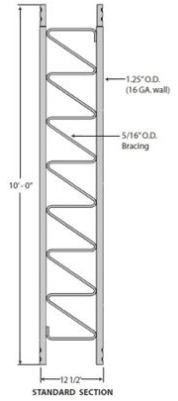
The planar delta design was challenged... defended... reconsidered. A triangular arrangement has regained supportA collapsible base was reiterated for this conceptConsideration for a stadium-cam style geometry did not gain traction (for full stability, down-wires would be needed, would interfere with build volume)Whatever the geometry, it'll need to be deploy-able within a 10'x10' booth space... something like a 5' square in the back middle might be perfect
Securing it to the floor or hang from the ceiling... the space will dictate what is possible
No matter what media is used, high-build is critical, light weight is critical
Expanding foam may have unwanted off-gassing, might be difficult to work with
Perhaps we could invent a filament that contains a blowing agent and it would expand as it prints
Polystyrene beads would be an excellent aggregate for printing
Hot-melt glue could coat the beads and be activated on printing
The polystyrene beads could also be expanded in the printing process... the hopper would be much smaller for it
Laser metal deposition is awesome, and we should do it, but with polystyrene
Too boring to watch print... and then so. much. material. handling..
Pneumatic conveyance of PS pellets would be suuuuper easy
not pneumatic, but hilarious, and sorta humane: https://www.youtube.com/watch?v=lO5TikjZU3c
Still radio tower sections, trucks still based on roller skate wheels
Still need to be light weight and rigid... carbon fiber triangles are the leading concept here
Aside from Jeff's Fanuc kit up in KS, we have several 1-off servos available, and one matched trio
Mitsubishi Melservo set from the tree mill
Need the serial protocol to make them work
A tape encoder was discussed
Software
Roland has volunteered to be responsible for the LinuxCNC work
Minutes of mtg - Jeff
Frame - Greg
Print Head - Shane
Greg Southerland
Sent from my iPhone
Jeff Hutchison
Although Roland Von Kurnatowski was mentioned in the minutes... I forgot to include him in the attendance list. I deeply regret any harm this may have caused.
The collapsible base was discussed. Greg suggested that the base should break into 3 parts with the connectors folding against the leg as shown (poorly) in the (crudely MSPaint'd) sketch below:
The folding base discussion led to a discussion about the print surface. A giant embroidery hoop was suggested:

There was a discussion regarding stepper motors. Servos remain in favor
Minutes of mtg - Jeff
Jeff Hutchison
Print mediaDRO tape, ultrasonic, laser interferometers, various different systems were discussed.
Decision makingvarious media were discussed.
Target deadlineUnless we can consider items decided, we'll never move forward
A working printer by December
Minutes of mtg - Jeff

Mark Sullivan
Jeff Hutchison
Greg presented his model on the overhead projector and the team discussed the design elements.
Team has returned to a traditional delta arrangement to solve the myriad problems brought about by "creative" geometry
Drive sprocket location was discussed, the position should be optimized
A vote was taken with regards to the number of pieces into which the delta would be disassembled.The option to have one single collapsible printer was rejected on the basis that it would potentially be too heavy and unwieldy.The option to separate the lower base independent of the legs was acceptedProvision of hinges didn't offer substantial benefit over simply breaking the thing down into component parts.Dimensional variations between components drive the request to use different bolt patterns so that the fit up is the same each time.
The top connections were not solved in the meeting
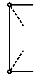
A poorly described and poorly defended concept (by a cold and cold medicine addled member) for "two sets of trucks" was shot down.. but now that said member has a clear head, the proper description is drawn (poorly) here:
Continuation at El Tiempo:The pulleys at the top stay at the top, the additional trucks become the top support and are engaged on the chain (with the normal trucks disengaged) for lifting and then locked to the frame at the top. The assembly takes place on the ground, is lifted into position, and then minimal (if any) ladder work for the assembler.
Various points were discussed... the extrusion media came up, and the previous problems of outgassing of noxious foams was reiterated. The concept of starch foam (like the cornstarch packing peanuts) was brought up, followed by the question of how they're made. The simplest answer is that a paste is cooked and extruded.
http://cdn.intechopen.com/pdfs-wm/34062.pdfhttp://www.google.com/patents/US20090170971http://www.sciencedirect.com/science/article/pii/S0032386102004974
Jeff Hutchison
Greg has made substantial progress in the model
Gear ratio for drives has been confirmed to give appropriate truck speed
Timing belts to be used with a 2 stage reduction
Bicycle chain (for reduction section) was suggested, decided against - it's cheaper, but not as good.
Truck guide wheels were modeled with pillow block bearings as well as the internal bearings... this is excessive
The counterweight is not expected to need any guidance... however, if necessary, a ring and rod can be added to keep it centered in the tower.
Carbon steel base pieces are proposed - the additional weight will keep the CoG for the unit low... this may not be necessary.
Aluminum will be used for the trucks
Print Media
Further discussion regarding starch foam was punctuated with hyperlinks from 24 May meeting.Actions
Minutes - Jeff
Add tolerances to drawings - Greg
Release to Manufacture - Greg
Waterjet parts - Roland
Assembly - Team
Starch/Polymer foam experimentation - Jeff
Jeff Hutchison
Will be constructed from 1" 80/20
A stiffener plate was detailed, proposed, decided against
If additional stiffness is needed, a different profile of aluminum extrusion may be used.
The arms are removable and securable for shipping (spring hasps are used in both positions)
BaseThe spring hasp design was challenged, but will certainly be robust enough for the application
The thickness of plates/sheet in the base was reconsidered.
1/2" plate is excessive, provides for drilling/tapping ends for bolting, but not needed
Through bolting can be acheived with nut plates, tacking nuts to the sheet metal, or other methods
Field-bolting will be with captive bolts to minimize chance of losing them
Print Media
Churros are extruded, deep fried, relatively low density, and deliciousActions
Oil-less fryers are really just convection ovens
https://www.amazon.com/BIG-BOSS-1300-Watt-Oil-Less-16-Quart/dp/B007P6SAZ4
A convection-section in the hot-end could be used to set cookable foam
Wave-guiding microwaves might be beyond the scope of the project.
Can PLA be foamed? Yes... it is an alternative to EPS, and used similarly.
http://www.sciencedirect.com/science/article/pii/S0079670014000392
If a source for foam PLA can be found, it might be a preferable alternative to foamed starch
Minutes - Jeff
Starch/Polymer foam experimentation - Jeff
Jeff Hutchison
Jeff Hutchison
Square tubing fits the 80/20 perfectly (a little tight)
Design discussion
PlanchetteWith Lajos available, Greg went through the design and discussed design decisions
The arm looks as if it might bind when the planchette is in the extreme outer position.
Greg continues to work to shrink the planchette and u-joints
Greg presented his u-joint design
Starch/Polymer foam experimentation - JeffMinutes - Jeff
Jeff Hutchison
Planchette
Further discussion regarding the potential for binding when the planchette is in the extreme outer position.
Jeff Hutchison
Greg presented the 3D model updates
Accuracy of one tenth of an inch was suggested and there were no objections heard.
Greg presented an elegant tensioning screw design
As shown (Torchmate style plate rail) was rejected by the team

Important to note that the rail only needs to extend through the motion range of the trucks (top of legs)
TrucksWith limited length ~6ft, the price of "proper" rails might not be prohibitive

Truck design is dependent upon linear rail (or tower w/ skateboard wheels) design
Arms and U-joints can be mounted to either trucks or rails as design evolves
Arms and U-Joints
Overall design is excellent - some debate about bushings vs bearings, no clear winner/loser in this design.
Speed holes in the arms will require substantial machining... unless they're available like that - think stop sign posts, but aluminum
Speed holes in the u-joints are not necessary
Path forward (action)
The straightness of radio towers is unknown (they're straight, but /how/ straight?) Mark will order the towers and we'll get started with them
The arms, planchette, and u-joint are in good enough shape design-wise to get started, we will proceed
Drive system may require subtle adjustment depending on whether skateboard wheel trucks or linear rail is selected
Greg Southerland
Sent from my iPhone
<image.png>
Continuation at El Tiempo:The pulleys at the top stay at the top, the additional trucks become the top support and are engaged on the chain (with the normal trucks disengaged) for lifting and then locked to the frame at the top. The assembly takes place on the ground, is lifted into position, and then minimal (if any) ladder work for the assembler.Various points were discussed... the extrusion media came up, and the previous problems of outgassing of noxious foams was reiterated. The concept of starch foam (like the cornstarch packing peanuts) was brought up, followed by the question of how they're made. The simplest answer is that a paste is cooked and extruded.http://cdn.intechopen.com/pdfs-wm/34062.pdfhttp://www.google.com/patents/US20090170971http://www.sciencedirect.com/science/article/pii/S0032386102004974
Jeff Hutchison
Mark Sullivan
Jeff Hutchison
Exactly zero fish were caught.. but a good time was had by all
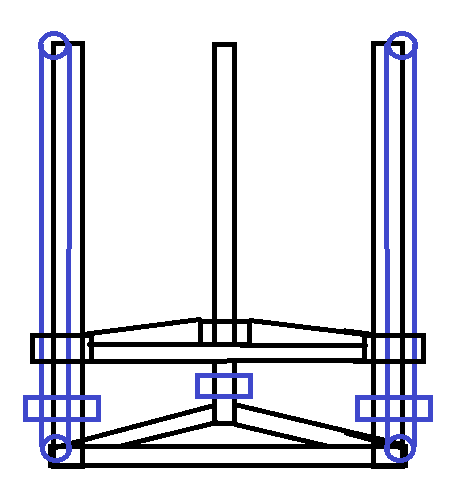
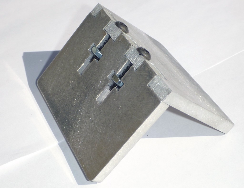
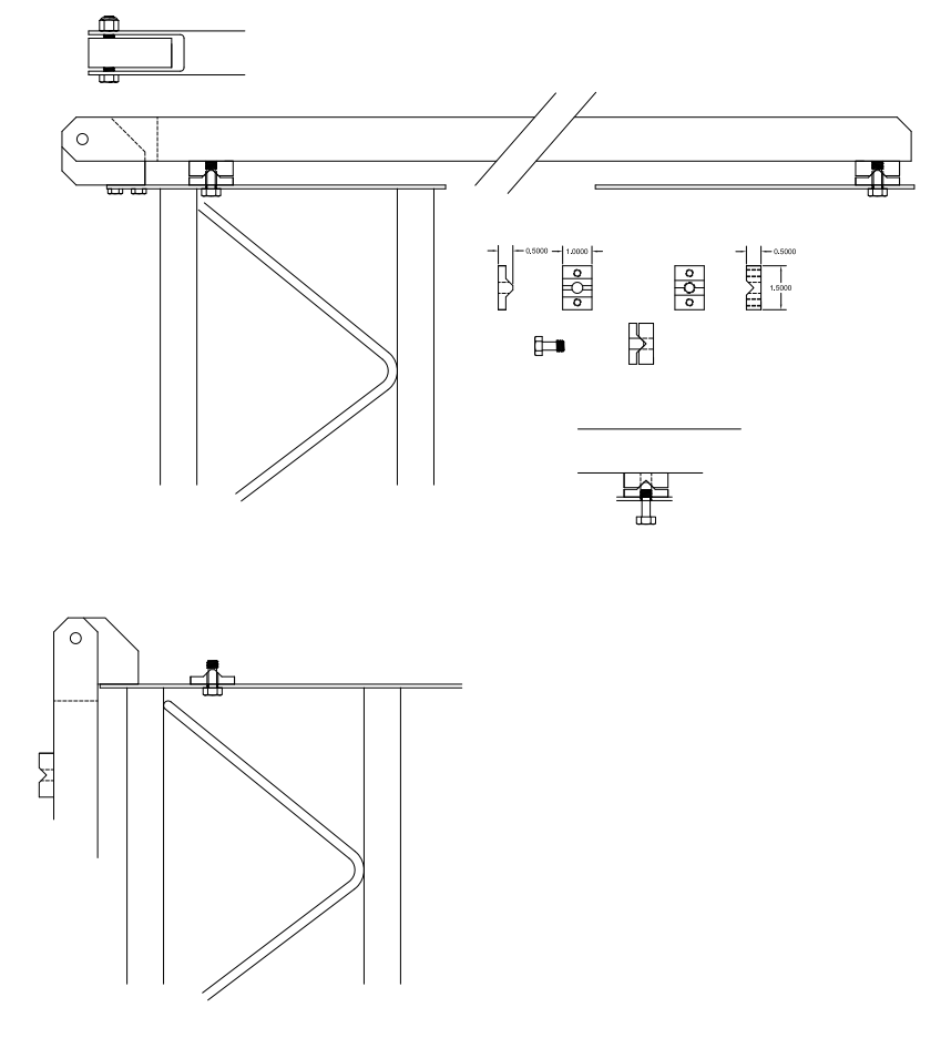
During the week, Greg modeled a cross-brace for mounting linear rails to the legs. The first pass at this design involved multiple pieces to be integrated.Mark's response: Instead of a separate saddle, the saddle could be cut into side walls of the channel. This would actually be easier to machine since it would mean cutting square stair-steps instead of an angle oblique to the Z axis.
The modified design offers multiple benefits over the original... it reduces part count and machining operations... the part would be machined in a single setup, with the stair steps cut as shown here: http://web.mit.edu/hyperbook/Patrikalakis-Maekawa-Cho/node213.html - work could be completed (if desired) with a tool change to ball end mill.However, the stair steps appeared to be rather coarse, and there was concern regarding stresses on the tubes of the legs. There was also concern related to the CAM work required to define the cuts.
Depth of the groove was discussed and Greg pointed out that a shallower groove would require a longer (non-standard) U-bolt... therefore the depth is perfect as designed.
The number of cross braces was discussed. The legs have zig-zag bracing at a regular frequency, and the linear shaft rail guides have bolt holes at a regular frequency... there may be interference between the bracing and the bolt holes.

Print MediaThe linear shaft rail guides are designed to be supported at every bolt hole - for a given deflection under a given load. The loads on this machine will be VERY small, and 100% support is not necessary - especially with the position tolerances that have been discussed.
Jeff has researched and ordered various substances to experiment with. The objective is to come up with a stable foam that can be fixed either with heat or chemically. A whip-cream'er and a soap foamer (to be used with an air-compressor) have been purchased for experimentation, along with a small inductive heater.
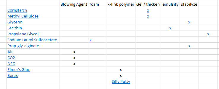
http://green-plastics.net/posts/76/qaa-help-with-cornstarch-pla-plastic-project/
As the components arrive over the course of the week, I'll mix, spray, curse, and document the results... I hope that next tuesday I'll have a demonstration ready (instead of just a big mess).
To unsubscribe from this group and stop receiving emails from it, send an email to txrxlabs+unsubscribe@googlegroups.com.
To post to this group, send email to txrx...@googlegroups.com.
Visit this group at https://groups.google.com/group/txrxlabs.
For more options, visit https://groups.google.com/d/optout.
--
You received this message because you are subscribed to the Google Groups "TXRX Labs" group.
To unsubscribe from this group and stop receiving emails from it, send an email to txrxlabs+unsubscribe@googlegroups.com.
To post to this group, send email to txrx...@googlegroups.com.
Visit this group at https://groups.google.com/group/txrxlabs.
For more options, visit https://groups.google.com/d/optout.
--
- Mark Sullivan -Fax (281)946-5978
--
You received this message because you are subscribed to the Google Groups "TXRX Labs" group.
To unsubscribe from this group and stop receiving emails from it, send an email to txrxlabs+unsubscribe@googlegroups.com.
Mark Sullivan

Greg Southerland
Sent from my iPhone
And, guess what just arrived ..
.<IMG_20160810_124845168.jpg>
On Wed, Aug 10, 2016 at 11:38 AM, Jeff Hutchison <jhutc...@gmail.com> wrote:
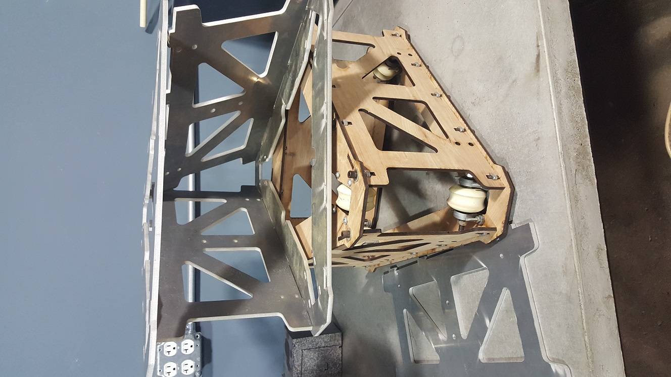
Delta-Bot meeting was held Tuesday, 9 Aug, 2016 at TXRX Labs, followed by El Tiempo. In attendance were Greg Southerland, Chris Kelley, Alijah Ballard, and Jeff Hutchison Meeting took place between 6:00PM and 7:00PM at TXRX, followed by continued discussion at El Tiempo, where we were joined by Shane Hooper and SuzyPuerto RicoExactly zero fish were caught.. but a good time was had by allThe 12 foot tall delta:Cross Brace
During the week, Greg modeled a cross-brace for mounting linear rails to the legs. The first pass at this design involved multiple pieces to be integrated.
<image.png>
Mark's response: Instead of a separate saddle, the saddle could be cut into side walls of the channel. This would actually be easier to machine since it would mean cutting square stair-steps instead of an angle oblique to the Z axis.
<image.png>
The modified design offers multiple benefits over the original... it reduces part count and machining operations... the part would be machined in a single setup, with the stair steps cut as shown here: http://web.mit.edu/hyperbook/Patrikalakis-Maekawa-Cho/node213.html - work could be completed (if desired) with a tool change to ball end mill.However, the stair steps appeared to be rather coarse, and there was concern regarding stresses on the tubes of the legs. There was also concern related to the CAM work required to define the cuts.Depth of the groove was discussed and Greg pointed out that a shallower groove would require a longer (non-standard) U-bolt... therefore the depth is perfect as designed.
The number of cross braces was discussed. The legs have zig-zag bracing at a regular frequency, and the linear shaft rail guides have bolt holes at a regular frequency... there may be interference between the bracing and the bolt holes.
<image.png><image.png>
Print MediaThe linear shaft rail guides are designed to be supported at every bolt hole - for a given deflection under a given load. The loads on this machine will be VERY small, and 100% support is not necessary - especially with the position tolerances that have been discussed.
Jeff has researched and ordered various substances to experiment with. The objective is to come up with a stable foam that can be fixed either with heat or chemically. A whip-cream'er and a soap foamer (to be used with an air-compressor) have been purchased for experimentation, along with a small inductive heater.
<image.png>
To unsubscribe from this group and stop receiving emails from it, send an email to txrxlabs+u...@googlegroups.com.
Mark Sullivan
Greg Southerland
Sent from my iPhone
To unsubscribe from this group and stop receiving emails from it, send an email to txrxlabs+u...@googlegroups.com.
Jeff Hutchison
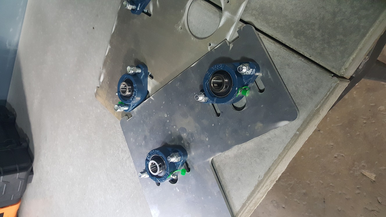
Radio towers are in, and they appear to be "in spec". It was noted that the cross bracing appears to be hand welded, and Greg expressed some small degree of concern about potential interference with the rollers on the trucks. Straightness can potentially be "measured" using a gun-barrel checking method described here
Chris has been modelling and has come up with an excellent solution.
Model shows T-Nut tab and slot construction, but team discussed welding after fitup as the machine will be mobile and subject to loosening forces.
Roller skate wheels, machined groove to match radio tower tube. Use 6 per truck. Mounted on economically priced pillow block bearings from eBay.
Jeff has done exactly zero experiments with the foam components ordered... these activities should ramp up in September
Chris has downloaded part models for a large format pellet extruder. Making the auger will pose the greatest challenge.
greg southerland
the target speed for the truck is 2500"/min
I really feel that Chris's truck design was excellent the only issue I have as seen is that I would like see the 4 of the wheel pillow block bearings in fixed holes and not mounted in slots. This will allow the truck position in relation to the rails to be fixed measurement. The other 2 wheels opposite if the arm mounts should be adjustable with slotted holes to allow tension to the rails. I love the truck design and it gets my vote. I hope the rest of you chimes in with yay or nay so we can advance the project further. the larger chain is the right way to go if off the shelf pulleys and sprockets can be sourced economically to obtain the 250'/min truck speed.
Sent: Wednesday, August 24, 2016 8:59 AM
To: txrxlabs
Subject: Re: [TX/RX Labs] Re: Delta Bot Meeting Notes
greg southerland
sorry the last sentence should read 2500"/min.
the larger chain is the right way to go if off the shelf pulleys and sprockets can be sourced economically to obtain the 2500"/min truck speed.
Sent: Wednesday, August 24, 2016 10:29 AM
To: txrx...@googlegroups.com
Subject: Re: [TX/RX Labs] Re: Delta Bot Meeting Notes
the target speed for the truck is 2500"/min
I really feel that Chris's truck design was excellent the only issue I have as seen is that I would like see the 4 of the wheel pillow block bearings in fixed holes and not mounted in slots. This will allow the truck position in relation to the rails to be fixed measurement. The other 2 wheels opposite if the arm mounts should be adjustable with slotted holes to allow tension to the rails. I love the truck design and it gets my vote. I hope the rest of you chimes in with yay or nay so we can advance the project further. the larger chain is the right way to go if off the shelf pulleys and sprockets can be sourced economically to obtain the 2500'/min truck speed.
Jeff Hutchison


Chris K.
The reason for having all the pillow block holes slotted was two fold:
1) Radial symmetry - Without it, a 2.5D trilateral shape has 2 wrong orientations for every correct one, whereas with it, all orientations are correct. This eliminates the possibility of getting half-way through assembly and realizing that one part is on the wrong way.
2) Preload of the wheels/bearings should allow the truck to remain in location relative to the ideal central axis of the towers, not the actual plane of any side of the tower. Otherwise, adjustments over time from wear will cause the position of the arm pivot points to move which will require adjustment of the kinematics parameters.
As for speed, I think 2500 IPM is unnecessarily fast. Our big router table's rapids are capped at less than half that speed and it is still our fastest machine. Also, I don't think any form of extruder we are likely to use will be able to keep up with a travel speed of much more than 100-150 IPM. The problem with needlessly high speeds is that they tend to require hard accelerations and decelerations which, given how many will be in a given print, will be much harder on the structure of the machine than transporting it.
Greg: Have you looked into the economics of using (#25) chain and sprockets for the reduction instead of timing belts?
greg southerland
Sent from my iPhone
--
You received this message because you are subscribed to the Google Groups "TXRX Labs" group.
To unsubscribe from this group and stop receiving emails from it, send an email to txrxlabs+u...@googlegroups.com.
greg southerland
Sent from my iPhone
Chris K.
On the final shaft, the one the tower chain and the second stage speed reduction is on, the hypothetical #25 chain would be under far less load than the tower chain due to the smaller chain being wrapped around a much larger diameter sprocket. If the radius of the larger #25 sprocket is more than about 3.5 times greater than the smaller #35 tower chain sprocket, then the tower-chain will fail before the smaller chain.
The chain/belt on the final speed reduction stage will see the highest load but the chain/belt on the first speed reduction stage will see the highest speeds.
My concern with the belt system is that they have problems when you get to the higher reduction ratios. When you have a small pulley coupled with a much larger one and you are trying to minimize the distance between shafts, you run in to the problem of not have enough teeth in engagement on the smaller one.
I was thinking that roller chain is less likely to skip on smaller sprockets (due to much deeper "teeth") than belts. Also, if necessary, we can manufacture larger roller chain sprockets much easier than timing belt pulleys to save costs and achieve higher reductions.
Another possibility is to use belts on a lower cost and lower-ratio first stage where the belt will see the highest speeds and use chain on the second stage with a higher ratio where the chain will see lower speeds but we can manufacture the larger sprocket at any size we want.
Finally, a properly tensioned chain drive won't have any more backlash than a belt drive. It will may be a bit noisier and less efficient, but I believe we have power to spare.
greg southerland
Sent from my iPhone
Jeff Hutchison
2500 in/min has been challenged for two primary reasons... it may be faster than is reasonable, and it increases the gear reduction required
Chris cited multiple examples of large machines (router and plasma tables) running far below this rate, and still being "fast"
Off-the-shelf (or easily waterjetted) components should govern the actual speed
Gear Reduction
Chris proposes chain and sprocket for the gear reduction
Sprockets can be water-jet cut cheaper than they can be purchased
Chain does not necessarily increase the backlash (at the penalty of efficiency and lifespan)
Timing cogs get very expensive in large sizes (needed for high reduction ratio)
Timing belts are more susceptible to slipping than a chain drive would be
If a two stage gear reduction is used, timing belts might be the better choice for the high-speed / low-torque stage, and then chain would be more suitable for the opposite.
Dimensional governanceThis problem is best solved mechanically (not on the electrical side)
Column tops and bottoms need to have the same dimensions so that when the bot is lying down, it's not slanted or tipping
CounterweightsTrucks need to have a smaller dimension so as not to touch the ground
The need for a counterweight was debated
Provision for a counterweight must be provided, even if no weight is added
The counterweight system does not need to be on the chain, can be separate
Extruder
The planchette has a mounting pattern that should accommodate all manner of extruders - and support experimentation
The connector for the extruder (or other end effector) will need to provide power and bi-directional signals. USB was proposed, networking and serial protocols were also proposed.
Some extruders may have a substantial weight, which exacerbates the issue of rapid movement and also the counterweights (which add inertia to the system)
Dynamics
Moving the weight of the extruder to a neutral point, or reducing its movement a-la the WASP 3D printer design (below) was discussed

The option to do this is highly dependent upon what type of extruder is installed... and the type that was under consideration (auger/pellet design) will not work in this arrangement. The WASP has a flexible short bowden tube between the floating extruder motor and the fixed hot end. In the auger/pellet design, the pellets are melted in the auger section, and a rigid, heated tube would be needed between the planchette and the floating extruder.
Motion Sensing and Control
Alijah informed the group that the HTC Vive's motion sensing system was open sourced recently
The refresh rate may be too slow for direct closed loop control, the information can be used for correcting the machine movement
Motion sensing, and other instrumentation don't have to be rigidly designed in - but provision for adding things should be a governing design concept
Modularity is the key to a platform that can be optimized iteratively.
To unsubscribe from this group and stop receiving emails from it, send an email to txrxlabs+unsubscribe@googlegroups.com.
To post to this group, send email to txrx...@googlegroups.com.
Visit this group at https://groups.google.com/group/txrxlabs.
For more options, visit https://groups.google.com/d/optout.
--
You received this message because you are subscribed to the Google Groups "TXRX Labs" group.
To unsubscribe from this group and stop receiving emails from it, send an email to txrxlabs+unsubscribe@googlegroups.com.
Jeff Hutchison
Pellet extruders have ooze issues... an "unloading piston" was discussed as a potential remedy. Part finishing was also discussed.
Mark Sullivan
Jeff Hutchison
Jeff Hutchison
Mark Sullivan
Jeff Hutchison
With the arrival of a new 3D printer (under evaluation for purchase), the team observed the design and discussed elements of overdesign
The overall build was incredibly (perhaps insanely) stout
The carriage was bizarrely large and looked heavy, with substantially more wire than needed
^ The WASP printer runs a hot-end with an RJ-45. Anything more than this is overkill (as evidenced by the fact that the WASP works beautifully)
Shane pointed out that it looked like a design that "grew" as they worked on it.
Other printers with plugs to the hot-ends use molex connectors - they work, but they are bulky and excessive
Further points of discussion - "closing the loop" on control... will not improve quality in these small and medium size FDM printers.
Stepper motors are more than sufficient to provide amazing accuracy and repeatability in a well designed (smaller) FDM printer (whether cartesian or delta)
The overall take-away is that as we design (and over design) our 3D printer, we should be mindful of the propensity towards over-design where it does not yield better output
Skateboard wheels have arrived, but the CNC lathe is down
Wheels are Shore A 99 hardness
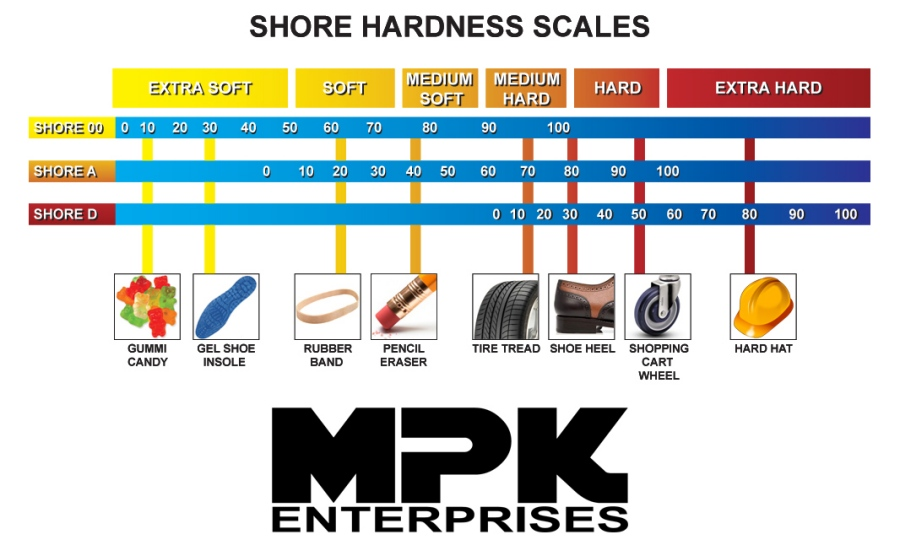
Regarding their maintainability: http://www.sdplastics.com/polyurethane_machining.html
Jeff Hutchison
Chris Kelley has completed a prototype truck in wood. The results proved what was expected - the rails are built to a level of tolerance that permits smooth movement without binding or loss of contact. Wheels will all be on slotted holes (as designed) to allow for tightening to the tower. Misalignment is not a concern due to the geometry of the design.
A taller truck will be made for the purpose of increasing stability. Note that this does not reduce the build area, as the length is added to the bottom of the truck.
Trucks will be aluminum and can be cut as soon as the model is updated for added length.
Base
Bases were proposed to be made from 10ga steel... a counter proposal of 3/8 Aluminum was made by Roland.
FundingSteel powdercoats nicely... aluminum may get banged up
Lab will reimburse members for their outlay - upon completion of working bot
ScheduleMark volunteered to take care of the servo's and drivers
PortabilityA working robot (exclusive of extruder) to be completed by the end of the year
Roland reminded the group that this must be deployable with minimal effort.
Jeff Hutchison
Mark presented a simplified design for the top frame - something akin to the connector below:

Greg has revised the model to include a motor with a brake and was able to keep the gearbox removable.There was also a discussion regarding the guide pins and assembly sequence
Delta-Bot meeting was held Tuesday, 13 Dec, 2016 at TXRX Labs, followed by El Tiempo. In attendance were Greg Southerland, Mark Sullivan, Chris Kelley, Alijah Ballard, Shane Hooper, Suzie, Roland Von Kurnatowski, Mike Reynolds, Jennifer Evans, and Jeff Hutchison Meeting took place between 6:00PM and 7:00PM at TXRX, followed by continued discussion at El Tiempo,
The 12 foot tall delta:
MotorsMotors must have brakes. This will add ~40mm to the length of the units, and will require some adjustment to the gearbox design.GearboxThe gearbox may remain removable - and possibly should remain removable to facilitate servicingTop and bottom boxes (what are we calling these?)
Many options for reorientation were discussedA lower-profile top was presented.. but lost favor after a discussion of fabrication impacts. One single alignment jig can be used for all six pieces if they are identical.
Another benefit of the full-height top box is that the struts will be identical to the bottom, and more stout than the presented alternative.
A drawback to the reversion is that there will be slightly more weight in the pod <- pods?? is that what we were calling them?ArmsArm design was brought up... a good modular design will allow for an interface point on the trucks that will permit arm design changes without impacting truck designDesign conceptsSlots were determined unfavorable where they are not absolutely necessary (e.g. for tensioning) Less error is expected in fabrication than in assembly.PortabilityRoland reminded the group (again) that this must be deployable with minimal effort.
Jeff Hutchison
Make it out of Aluminum - unanimous
Cost of 5051 sheet not excessive compared to steel - much stiffer
Some scrap in shop - not enough, will need to order more
PortabilityGreg has been doing layouts for cuts and material estimating
The unit (in whole or in part) must be deployable through a standard size door
A collapsing unit would be very cool, but will be all the mass, and pretty large
More pieces isn't ideal, but is better for the installers if they are easier to handle - and fit through a door.
Further refinement of Mark's top frameConnectors can be attached to 3 tower uprights (in-plane) or 4 (out of plane)
Connectors do not need to be above top plate
Plate can be installed permanently - with connectors add/remove for (dis)assembly
Methods of connection between connectors and top plate discussed
Magic magnets
Guides (cone and hole) can be used to ensure alignment
Long wrench
Push-push
Roland suggested U-bolts instead of splitting the connectors
Greg presented his design for the arm joint
Chris reminded the team that he had already designed a joint
Both designs were similar
Chris used a shoulder bolt in his design
Greg had installed his bearings on the bar instead of the yokes
Both designs involved a fair bit of machining and setups
Both are good
Discussion revolved around chain connection - master link will be attached to truck.. will be sufficiently strong for service
As the design is to be disassembled, connectors will be needed
6 bucks for a five pack - (6 pin ea)

15 bucks ea - but they're IP-68 and 12 pins...
Jeff Hutchison
Aluminum was questioned... refer to previous minutes for details.
Portability and top pod design
Greg had shared a design idea for a folding upper brace, to be deployed on the ground before erecting the tower leg.
This design was further refined from a 270° fold to a 90° fold
effectively flipping the pivot point from being on top of the plate to being under the plate. In order to ensure adequate stiffness, the upper plate will be backed by a section of aluminum square/rectangle tubing (as shown in the crude sketch above)
Pins a-la McMaster Carr will ensure alignment


Jeff Hutchison
Jeff Hutchison
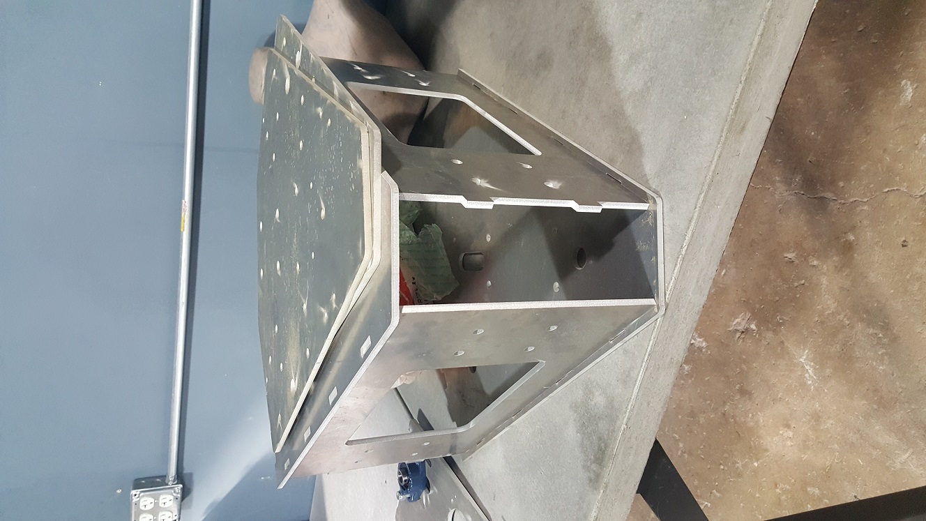
Delta-Bot meeting was held Tuesday, 13 Jun, 2017 at TXRX Labs, followed by El Tiempo. In attendance were Greg Southerland, Daniel, Mark Sullivan, Alijah Ballard, and Jeff Hutchison, followed by continued discussion at El Tiempo,More waterjet cutting after tolerances were revised - the carriage bolts now fit perfectly in the slots. Photos of the wooden prototype carriage and aluminum components are attached.During the meeting, a Gantt chart was developed to detail all remaining activities (attached).In the chart, the current week is 9, based on the work that has been ongoing (for much more than 9 weeks, haha).Many of the activities are "roll-ups" of multiple activities, but the resolution of the chart is 1 week.We intend to schedule assembly sessions in addition to our regular meetings so that the entire team can work together to complete activities.Greg proposed that we change venue for next week's meeting - Laurenzo's will be the place.