Tokyo Hackerspace arduino clone

147 views
Skip to first unread message

fakufaku

unread,
Jul 11, 2012, 2:44:27 AM7/11/12
to tokyohac...@googlegroups.com
I was talking yesterday with Richard about Arduino clones, and how easy it is to make one (a very crude, and cheap, one to be sure).

It could be quite nice to create one that's extremely simple and has few parts (à la Diavolino) that could be all grabed from Akizuki.

We could have the PCBs fabbed and then anyone can buy the parts from Akihabara.

I think it would be great for several purpose:

1) Really cheap (< JPY1000 all parts and PCB included, we could sell kits for profit, PCBs only for less profit)

2) Great as introduction to soldering

3) Great for the introduction to arduino class

4) We would always have an arduino handy at the hackerspace

5) It would fit nicely in the vending machine! We could sell it on the website. There could be a discount for members, or you could get just the PCB when you join so that you readily have a first project to do at the space (get the parts at akizuki and put it together).

6) It would have the hackerspace logo and stuff, it could have a funky shape (a sushi ?).


Essentially it would be a breakout board for the atmega328p without all the bells and whistles (maybe 5V regulator is nice, but you could get that from USB).

We could make similar boards for other AVR or PIC (attiny would be nice and handy).

What do you think ?

Torsten Wagner

unread,
Jul 11, 2012, 5:30:57 PM7/11/12
to tokyohac...@googlegroups.com

7) It would make a great final end of a crazy THS guided Akihabara tour. Could be a geek tourist kit.

> --
> You received this message because you are subscribed to the Google Groups "TokyoHackerSpace" group.
> To view this discussion on the web visit https://groups.google.com/d/msg/tokyohackerspace/-/mdQkK1yxguwJ.
> To post to this group, send email to tokyohac...@googlegroups.com.
> To unsubscribe from this group, send email to tokyohackerspa...@googlegroups.com.
> For more options, visit this group at http://groups.google.com/group/tokyohackerspace?hl=en.

fakufaku

unread,
Jul 11, 2012, 7:33:11 PM7/11/12
to tokyohac...@googlegroups.com
Okay, so I spent a few hours yesterday and got a schematics and preliminary board placement (no routing yet).

It's all on the hackerspace's github:


I went for 5x5cm board because it is cheapest to get done on SeeedStudio. And a small footprint board is nice.

However, that has a few drawbacks too:
- Cluttered board with little space for art and logos
- Slightly more difficult to solder (but not much I think)
- Most importantly, compatibility with arduino shields is lost (note that the design is not 100% compatible as it doesnt have *both* 5V and 3.3V regulators in the first place).

So please, give me your feedback on this.

lauren shannon

unread,
Jul 11, 2012, 7:40:12 PM7/11/12
to tokyohac...@googlegroups.com
Logo loss is a biggie...
does the board you did still fit nicely in vending machine?
> --
> You received this message because you are subscribed to the Google Groups
> "TokyoHackerSpace" group.
> To view this discussion on the web visit
> https://groups.google.com/d/msg/tokyohackerspace/-/Emia7g0qqZ0J.
>
> To post to this group, send email to tokyohac...@googlegroups.com.
> To unsubscribe from this group, send email to
> tokyohackerspa...@googlegroups.com.
> For more options, visit this group at
> http://groups.google.com/group/tokyohackerspace?hl=en.


--
We LOVE Food and Wine!

Try my catering company at
www.moonandback.jp

and our restaurant and wine bar
www.kimonowinebar.com

fakufaku

unread,
Jul 11, 2012, 8:07:09 PM7/11/12
to tokyohac...@googlegroups.com
There will be a logo on it, but less art mostly. I wanted first to make a Japaney Tokyoish shape, but it will not be possible at that shape. This is not written in stone though, that's why I'm asking. PCB price shouldn't matter too much if we end up making really many of them.

At 5x5cm I expect it to fit nicely in the vending machine.

R
Message has been deleted

Mikele

unread,
Jul 11, 2012, 10:46:48 PM7/11/12
to tokyohac...@googlegroups.com
neat look


On Thu, Jul 12, 2012 at 11:09 AM, Marco <marco....@gmail.com> wrote:
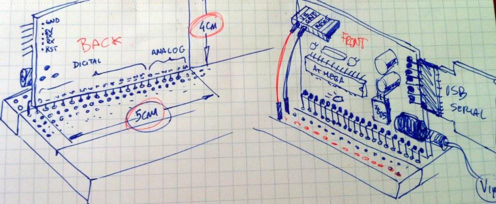
Change the location of connectors prevents the use of the Arduino shields.
However there is no Arduino with the connectors on a single side like that:

http://dangerousprototypes.com/wp-content/media/2012/07/pic2550600.jpg

A layout as this would eliminate several cables during prototyping, and could represent an original alternative to all the other low-cost Arduino clones.

--
You received this message because you are subscribed to the Google Groups "TokyoHackerSpace" group.
To view this discussion on the web visit https://groups.google.com/d/msg/tokyohackerspace/-/_navr_MR9BYJ.

fakufaku

unread,
Jul 12, 2012, 12:45:49 AM7/12/12
to tokyohac...@googlegroups.com
Oh, that's neat. But it doesn't fit in the 5x5cm.

It is very frustrating that the normal arduino is 53mm wide... I wonder if we can squeeze shield compatible pins in just 5cm. I will try.

Otherwise, having the pins alligned on 100 mil grid allows to plug it on a bread board. not bad either.

R

fakufaku

unread,
Jul 12, 2012, 2:18:08 AM7/12/12
to tokyohac...@googlegroups.com
Right! This might be playing with the minimum spacing between hole and board side.

50 - 19x2.54 = 1.74mm left, this might not be enough since there still are 2 half holes that must fit, and the spacing.

I will give it a try tonight that could be nice.

On Thursday, July 12, 2012 2:26:36 PM UTC+9, Marco wrote:
Anyway, a side of 5cm could be enough for 20 pins (14 digital + 6 analog).

--
Marco

MRE

unread,
Jul 12, 2012, 7:57:12 AM7/12/12
to tokyohac...@googlegroups.com
Original arduino style layout is likely best.
Least likely to confuse newbs.
As for fiting in the machine it can go into the box at an angle.

But a second "tokyo hacker style" board in the shape of a suhi, or geisha, or tokyo tower , or a sumo dude would be cool.. maybe a super hero shape?

Marco

unread,
Jul 12, 2012, 9:26:56 AM7/12/12
to tokyohac...@googlegroups.com

Il giorno giovedì 12 luglio 2012 20:57:12 UTC+9, MRE ha scritto:

But a second "tokyo hacker style" board in the shape of a suhi, or geisha, or tokyo tower , or a sumo dude would be cool..  maybe a super hero shape?

ULRAMANINO!? (ウルトラマニノ)

--
Marco
 
Message has been deleted

fakufaku

unread,
Jul 12, 2012, 11:53:10 AM7/12/12
to tokyohac...@googlegroups.com
Yeah, exactly! I'm thinking of making several PCBs using the same parts. So we can have a small on, a normal one, an SMD one and aGeisha one. But let's make one first...

Chris

unread,
Jul 12, 2012, 11:56:21 AM7/12/12
to tokyohac...@googlegroups.com, tokyohac...@googlegroups.com
I

Sent from my iPad

On Jul 12, 2012, at 8:53 AM, fakufaku <faku...@gmail.com> wrote:

> Yeah, exactly! I'm thinking of making several PCBs using the same parts. So we can have a small on, a normal one, an SMD one and aGeisha one. But let's make one first...
>
> --
> You received this message because you are subscribed to the Google Groups "TokyoHackerSpace" group.
> To view this discussion on the web visit https://groups.google.com/d/msg/tokyohackerspace/-/JaJxKmioFEIJ.

Chris

unread,
Jul 12, 2012, 11:57:14 AM7/12/12
to tokyohac...@googlegroups.com
I say we plan it forever and then do nothing. Theres Something strangely comfortable in that.

Sent from my iPad

On Jul 12, 2012, at 8:53 AM, fakufaku <faku...@gmail.com> wrote:

> Yeah, exactly! I'm thinking of making several PCBs using the same parts. So we can have a small on, a normal one, an SMD one and aGeisha one. But let's make one first...
>
> --
> You received this message because you are subscribed to the Google Groups "TokyoHackerSpace" group.
> To view this discussion on the web visit https://groups.google.com/d/msg/tokyohackerspace/-/JaJxKmioFEIJ.
> To post to this group, send email to tokyohac...@googlegroups.com.
> To unsubscribe from this group, send email to tokyohackerspa...@googlegroups.com.
> For more options, visit this group at http://groups.google.com/group/tokyohackerspace?hl=en.in

fakufaku

unread,
Jul 12, 2012, 7:13:34 PM7/12/12
to tokyohac...@googlegroups.com
No. Actually, I'm working on it. Now.

R

Marco

unread,
Jul 12, 2012, 10:56:07 PM7/12/12
to tokyohac...@googlegroups.com
Sushi/geisha shaped board apart, I thought something like this...
ultramanino.jpg

fakufaku

unread,
Jul 12, 2012, 11:59:01 PM7/12/12
to tokyohac...@googlegroups.com
Marco,

I tried and 20 pins do not fit in 5 cm. Yet.

50 mm is 1968.5 mil. 20 pins at 100 mil pitch is 1900 mil, which leaves only 34 mil on both side, not enough to accommodate the pin pad. I will try reducing the size of the pads on both sides and see if that fits.

MRE,
Keeping shield compatible has even worse version of the same as that way, all the pins are dangerously close to the side of the board.

MRE

unread,
Jul 13, 2012, 1:49:32 AM7/13/12
to TokyoHackerSpace
frakin size limitations!

Marco; nice render.

Pieter

unread,
Jul 13, 2012, 2:36:56 AM7/13/12
to tokyohac...@googlegroups.com
I am not against reinventing the wheel,

But there are great choices for arduino's:
1. The amazing Fredboard from Akiba, my personal favorite - perhaps Akiba can offer them in Kit form for the soldering experience
2. The Freakduino (of course)
3. Adafruit sells a nice variety, and THS members get a hard 40% discount

You can also find dirt cheap kits in Akihabara these days (forgot, but got some under Y2000, all through hole, with USB)

Anyways - it looks like a fun project :-[]

Pieter

fakufaku

unread,
Jul 13, 2012, 4:15:28 AM7/13/12
to tokyohac...@googlegroups.com
Pieter,

All the boards you mentioned are amazing. But I feel it would be nice to have a hackerspace branded board.

In addition it would fill the following needs:

1) less than 600yen in parts (w/o power supply).
2) Having PCBs at the hackerspace when you need an arduino, but only have the atmega328p chip lying around in your box
3) Smallish form factor
4) Modular power supply (regulator or battery booster)
5) A nice THS logo!

R

fakufaku

unread,
Jul 13, 2012, 4:16:49 AM7/13/12
to tokyohac...@googlegroups.com
6) A nice project to start from when learning
  - soldering
  - arduino
  - eagle cad

R

Lauren Shannon

unread,
Jul 13, 2012, 4:21:15 AM7/13/12
to tokyohac...@googlegroups.com, tokyohac...@googlegroups.com
And fits in vending machine!!!

Sent from my iPhone
--
You received this message because you are subscribed to the Google Groups "TokyoHackerSpace" group.
To view this discussion on the web visit https://groups.google.com/d/msg/tokyohackerspace/-/JbRsJSuTIX0J.

Marco

unread,
Jul 13, 2012, 5:29:02 AM7/13/12
to tokyohac...@googlegroups.com
Il giorno venerdì 13 luglio 2012 14:49:32 UTC+9, MRE ha scritto:

Marco; nice render. 

It is my current CAD system, I'm glad you like it :)

--
Marco

MRE

unread,
Jul 13, 2012, 9:47:50 AM7/13/12
to TokyoHackerSpace
Is your CAD open sourced?

Pieter

unread,
Jul 14, 2012, 1:08:16 AM7/14/12
to tokyohac...@googlegroups.com
Cool! So now we'll have 4 cool boards. Will it have the USB chip, or use external USB dongle?

Pieter

Marco

unread,
Jul 14, 2012, 1:59:29 AM7/14/12
to tokyohac...@googlegroups.com
Only the hardware, the software (two FriXion pens) are copyrighted by Pilot :)

--
Marco

fakufaku

unread,
Jul 16, 2012, 4:02:33 AM7/16/12
to tokyohac...@googlegroups.com
There we go.

I had to move the pin 0 and A5 towards the centre of the board to fit in the DRC. It might be too tight so I need to check the header can fit in practice.

R

Marco

unread,
Jul 16, 2012, 7:35:50 AM7/16/12
to tokyohac...@googlegroups.com
Sugoi :)

Marco

unread,
Jul 16, 2012, 11:37:46 PM7/16/12
to tokyohac...@googlegroups.com
2 questions:
Why did you use a 3.3V regulator, instead of a 5V regulator?
What exactly do the circuit with the TH-HT77xxA? It is something like an additional system to power the board also with two AA batteries?

--
Marco

fakufaku

unread,
Jul 17, 2012, 12:03:59 AM7/17/12
to tokyohac...@googlegroups.com
Marco,

Why did you use a 3.3V regulator, instead of a 5V regulator?

I try to leave many options opened, depending on what components you buy. So the system can be used at 5V by using 5V regulator and a 16MHz crystal

or at 3.3V using a 3.3V regulator (same footprint as the 5V regulator) and an 8MHz crystal (also same footprint)

The datasheet of the regulator IC:
 
What exactly do the circuit with the TH-HT77xxA? It is something like an additional system to power the board also with two AA batteries?

Yep, it's a step-up converter so that you can power the board from batteries. Again, you can do that at either 5V or 3.3V.
and the datasheet: http://bit.ly/Nsuxkw

The idea is not necessarily to have everything on the board, but to populate only what you want. If you only want to work from USB, you wouldn't really need a regulator, so you really just need the atmega chip and a few caps (and the FTDI-serial board).

Cheers,
Robin
 

--
Marco

Marco

unread,
Jul 17, 2012, 1:21:22 AM7/17/12
to tokyohac...@googlegroups.com
The idea is not necessarily to have everything on the board, but to populate only what you want. If you only want to work from USB, you wouldn't really need a regulator, so you really just need the atmega chip and a few caps (and the FTDI-serial board).

So, what do you think about a layout like this?

The circuit with the H-HT77xxA is in the upper part of the board and could be connected to the rest with bridges (scrap reophores), or allowing the track of VCC and GND to pass trough two of three "breakable connections".
(
Sorry, I have no idea about what could be the correct name of those connections in English).

Eventually, if not needed, can be removed to save space or to be used into another project.

Finally (I'm sure you will hate me for this):
Reversing the order of the pins (nobody need to look at the components on the board when it is connected to a breadboard) the numbers will match with those of the breadboard and the logo on the back will be prominently :)

--
Marco


THarduino.jpg

fakufaku

unread,
Jul 17, 2012, 1:41:44 AM7/17/12
to tokyohac...@googlegroups.com
Marco,

I appreciate the input, but I think I will get a prototype of this version first, and then we can look at improvements. Main reason is the amount of time I decided to put into this (a few hours over a week-end). I do however have a few reservations about your suggestions.


The circuit with the H-HT77xxA is in the upper part of the board and could be connected to the rest with bridges (scrap reophores), or allowing the track of VCC and GND to pass trough two of three "breakable connections".
(
Sorry, I have no idea about what could be the correct name of those connections in English).

This is nice, but it might not be allowed by the board house (at least seeed, which I use). Second, the board is fairly small already for a through hole board. It could get smaller, but then it wouldn't be beginner friendly for the soldering anymore.
 
Eventually, if not needed, can be removed to save space or to be used into another project.

For project requiring super small sized board, it is always possible to get a different arduino board with SMD chip (FIO, pro, mini, etc). 

Finally (I'm sure you will hate me for this):
Reversing the order of the pins (nobody need to look at the components on the board when it is connected to a breadboard) the numbers will match with those of the breadboard and the logo on the back will be prominently :)

I will not hate you because I will not do it :)

You can always reverse the board, or plug it to the other side of your bread board. I am also pretty sure that not all bread boards have the same numbering order :)

Also, I'm lazy and the routing of the pin header was a pain.

But that gave me an idea, that I might implement or not. I could add a 2-pin header with VCC and GND that would plug in the side power strip. So that if you plug the board horizontally, you also power the bread board (without extra jumpers).

Just want to add that if you want to participate more actively in the development, I can add you to the Github team for this project. If you also would just like to fork it and continue it, then please go ahead and do so.

Cheers,
Robin


--
Marco


AbH Belxjander Draconis Serechai

unread,
Jul 17, 2012, 1:48:03 AM7/17/12
to tokyohac...@googlegroups.com
This seems to be similar to everything done for the various reprap
electronics options...

Take an AVR, and building a board around it...

What sort of functions will these boards actually make available?
> --
> You received this message because you are subscribed to the Google Groups
> "TokyoHackerSpace" group.
> To view this discussion on the web visit
> https://groups.google.com/d/msg/tokyohackerspace/-/NbVGyhcWODwJ.

fakufaku

unread,
Jul 17, 2012, 3:04:37 AM7/17/12
to tokyohac...@googlegroups.com
What sort of functions will these boards actually make available?

Not sure what you mean. This is basically an Arduino in a smaller form factor with a few option left open for the power supply. It is also lacking the usb-to-serial chip to lower cost and assembly complexity. You should be able to use for almost anything you use an arduino for.

Cheers,
Robin
 

MRE

unread,
Jul 17, 2012, 3:27:17 AM7/17/12
to TokyoHackerSpace
lookin snazzy

Richard Frankum

unread,
Jul 17, 2012, 10:25:52 PM7/17/12
to tokyohac...@googlegroups.com
> You should be
> able to use for almost anything you use an arduino for.

Missed you last night, Robin! How are you going to prototype this board?
Come to think of it, how did Safecast proto their designs? Will you
borrow Akiba's mill?

>
> Cheers,
> Robin


--
--Richard Frankum

Marco

unread,
Jul 18, 2012, 2:52:55 AM7/18/12
to tokyohac...@googlegroups.com
Do not worry, I'm having so much fun to bother you with my annoying claims, and I am  happy when you find interesting even the 10% of what I write :D

How many pieces do you plan to taking with the first order?
I'd take some if possible.

--
Marco

fakufaku

unread,
Jul 18, 2012, 3:00:36 AM7/18/12
to tokyohac...@googlegroups.com
Good :) Glad you enjoy the project.

I will order the minimum quantity, 10. That should be plenty for alpha users and we'll find out if there are modifications worth doing (and usually there are). Then we can order more, and give them a pretty color if we order enough (green PCB is at no extra cost, red/blue/green/yellow are available for +10$, black +20$, fixed, so only worth when you order large quantity).

I'm mostly worried about the 20-pin connector that I shorted a little. It might be too much mechanical stress... But we'll see.

R

Richard Frankum

unread,
Jul 18, 2012, 3:04:19 AM7/18/12
to tokyohac...@googlegroups.com
On Wed, Jul 18, 2012 at 4:00 PM, fakufaku <faku...@gmail.com> wrote:
> Good :) Glad you enjoy the project.
>
> I will order the minimum quantity, 10. That should be plenty for alpha users

Dang, now I have to think of a project that requires an Arduino!

If only someone had a book or something I could refer to!

--
--Richard Frankum

fakufaku

unread,
Jul 18, 2012, 3:17:25 AM7/18/12
to tokyohac...@googlegroups.com
Richard,

If you're lacking a project idea, my rice cooker just passed away. Would you like to resurrect it ? :)

R

Kalin KOZHUHAROV

unread,
Jul 18, 2012, 3:44:46 AM7/18/12
to tokyohac...@googlegroups.com
Hi Robin,

Great new project! If only I had more time...

On Mon, Jul 16, 2012 at 5:02 PM, fakufaku <faku...@gmail.com> wrote:
> There we go.
> https://github.com/TokyoHackerspace/Otemba/blob/master/Otemba_brd.png
>

Quick notes/nut-picking:

1. number the JP4 header pins as the schematic (D1..D13) and like the
analod A1..5
2. label the LED1 on the mask
3. add a testpoint hole (or more in various corners) where there is
space for ground;
4. I only see JP1, JP3 and JP4... where is JP2? consider labeling the
connectors on the mask
5. What happens when both battery and DC are connected? Need a jumper?
or DC jack switch?
6. Add a line of holes next to JP1 for test points (e.g. those
http://www.aitendo.com/product/2514 )
7. Any space left for a tiny piezo?

Cheers,
Kalin.

fakufaku

unread,
Jul 18, 2012, 4:22:45 AM7/18/12
to tokyohac...@googlegroups.com
Kalin, glad you like it. You can get one when I'll have them made!


1. number the JP4 header pins as the schematic (D1..D13) and like the
analod A1..5
2. label the LED1 on the mask

I try to keep the silk screen relatively label free. I just keep the caps and resistors to avoid confusion when building the board. Pin numbering match traditional arduino scheme (no 'D' for digital pins).
 
3. add a testpoint hole (or more in various corners) where there is
space for ground;

Hum, good idea. I will add at least a pad for ground.
 
4. I only see JP1, JP3 and JP4... where is JP2? consider labeling the
connectors on the mask

Can do ;)
 
5. What happens when both battery and DC are connected? Need a jumper? 
or DC jack switch?


If both are populated, then both shouldn't be connected at the same time I suppose. I don't think this would be a big problem if they are at the same voltage though. FTDI chip should have a protection circuit (at least in my experience regulator + USB-ftdi dongle works fine together).

I don't think a jumper is necessary since both are not necessary at the same time. 
 
6. Add a line of holes next to JP1 for test points (e.g. those
http://www.aitendo.com/product/2514 )

meh
 
7. Any space left for a tiny piezo?

Piezo is not part of the concet. The led is only there so that the board can be readily tested.

Cheers,
R
 

Cheers,
Kalin.

Richard Frankum

unread,
Jul 18, 2012, 4:34:36 AM7/18/12
to tokyohac...@googlegroups.com
No time. Speaking of which, I have a clock to program!

> R

--
--Richard Frankum

fakufaku

unread,
Jul 18, 2012, 4:44:14 AM7/18/12
to tokyohac...@googlegroups.com
I give you a hundred decimal hours to fix it!

BTW, I found a bug in the labeling of some pins, if you can make a mental note:

VCC <-> SDA are reversed
RESET <-> SCL are reversed 

I am actually going to use the clock to fix a broken oven I got and bake delicious cakes!

Cheers,
Robin

Richard Frankum

unread,
Jul 18, 2012, 4:54:45 AM7/18/12
to tokyohac...@googlegroups.com
On Wed, Jul 18, 2012 at 5:44 PM, fakufaku <faku...@gmail.com> wrote:
> I give you a hundred decimal hours to fix it!

Oh, no way. It's in my five (French Revolutionary) year plan.

> BTW, I found a bug in the labeling of some pins, if you can make a mental
> note:

On the clock PCB? Noted.

> I am actually going to use the clock to fix a broken oven I got and bake
> delicious cakes!

Now *that* is where you have to be careful with metric. I heard of a
friend who tried to bake cookies at (normal in F) 350 degrees and
didn't read the Japanese oven right...

MRE

unread,
Jul 18, 2012, 5:43:15 AM7/18/12
to TokyoHackerSpace
cough

On Jul 18, 4:04 pm, Richard Frankum <richard.fran...@gmail.com> wrote:

MRE

unread,
Jul 18, 2012, 5:53:36 AM7/18/12
to TokyoHackerSpace
as for labeling, its common to leave out the D, and only mark the
Analogs..
Or do them in "blocks" such as the group is surrounded with brackets,
and the words "digital" and "analog" written on them.
Given that this is not really for an ultra newbie anyway, I think you
are fine with the short hand labels.

TX/RX need to be clear, and possibly marking off the pins with
interrupt/counter functionality, but not absolutely essential.

RE: multiple power supplies:
Any supplies in parallel should not cause any issues, so long as the
routing is correct.
So, a battery pack, the usb dongle and some power supply input on a
pin all three connect together, its no issue, provided:
1: They are at the same voltage, or reasonably close. 5 volts out of
the USB dongle might swamp a 3.3 regulator, causing it to shut down
(its reverse biased).
2: 5 volts from the USB dongle feeding in parallel with a few weak AA
batteries will "attempt" to charge them, which is no good for
traditional batteries, but actually a good thing if using NiCads.
3: It may be useful to put some diodes on all the supplies, such that
a high voltage on one supply wont feed back to the other.

Its pretty normal to have multiple supplies connected during
programming.. usually not an issue, so long as routing is correct, and
supplies plugged in correctly. Again, diodes would prevent most damage
if a supply is connected backwards (except for the offending supply).

Taylan Ayken

unread,
Jul 18, 2012, 6:49:06 AM7/18/12
to tokyohac...@googlegroups.com
Most Arduino's have some sort of mechanism that disables USB power if there is 5V present on the DC connector. Of course they use, wait for it, MOSFETs! You can always go with a Schottky diode but they have a ~0.4V voltage drop whereas with a MOSFET you have to only consider the on resistance and maximum current draw which is usually lower.

If there are no protection mechanisms present on the board and you plug DC connector and USB at the same time, you are essentially using the trace between those two inputs as a resistor to balance the voltages. This is a common practice if you are using, for example, multiple 7805 ICs to provide enough current, there will be a slight imbalance between regulators and you adjust the traces to act like resistors. But if you are not careful and if there is too much of an imbalance, you'll destroy that trace.

Just my 2 yen.

BTW: Nice work Robin!


From: MRE <epre...@gmail.com>
To: TokyoHackerSpace <tokyohac...@googlegroups.com>
Sent: Wednesday, July 18, 2012 6:53 PM
Subject: [THS:19151] Re: Tokyo Hackerspace arduino clone
--
You received this message because you are subscribed to the Google Groups "TokyoHackerSpace" group.
To post to this group, send email to tokyohac...@googlegroups.com.
To unsubscribe from this group, send email to tokyohackerspace+unsub...@googlegroups.com.

fakufaku

unread,
Jul 18, 2012, 10:09:48 PM7/18/12
to tokyohac...@googlegroups.com, Taylan Ayken
MRE and Tayken, thanks for input on power supply.

So the take home message is that I will leave it the way it is because 

1) AFAIU it will not blow up or smoke if everything is wired normally and no other voltage than 3.3V and 5V are used.

2) It is considerably less parts and complexity

3) Most of the time only a single power supply is used. With the exception of the occasional programming of the board.

Would you mind checking the schematics to make sure 1) is correct ?

Thanks!
Robin

Taylan Ayken

unread,
Jul 18, 2012, 10:33:16 PM7/18/12
to tokyohac...@googlegroups.com
OK, that was just to clear some stuff in people's minds, no need for them if user is careful. Arduino team includes that as it can be quite a headache if beginners blow up their boards. No good for publicity.

It looks OK to me, maybe changing the net name of VREG to VIN is better? I have a couple of questions, sorry if you answered them before:

1) It uses a 3.3V FTDI adapter, right? That is if you populate the original parts on the schematic for a 3.3V system.
2) We can swap everything for 5V equivalents and get a 5V system? Especially with the battery boost circuitry.


From: fakufaku <faku...@gmail.com>
To: tokyohac...@googlegroups.com
Cc: Taylan Ayken <taylan...@yahoo.com>
Sent: Thursday, July 19, 2012 11:09 AM
Subject: Re: [THS:19158] Re: Tokyo Hackerspace arduino clone

--
You received this message because you are subscribed to the Google Groups "TokyoHackerSpace" group.
To view this discussion on the web visit https://groups.google.com/d/msg/tokyohackerspace/-/FFIW1HZcJ_QJ.

To post to this group, send email to tokyohac...@googlegroups.com.
To unsubscribe from this group, send email to tokyohackerspa...@googlegroups.com.

Kalin KOZHUHAROV

unread,
Jul 19, 2012, 12:25:31 AM7/19/12
to tokyohac...@googlegroups.com
On Thu, Jul 19, 2012 at 11:33 AM, Taylan Ayken <taylan...@yahoo.com> wrote:
> It looks OK to me, maybe changing the net name of VREG to VIN is better?

Hmm, I thought VREG meant VoltageREGulated.... looked at the
schematic, that one is labeled VCC (as usual)...

BAT_IN and DC_IN might be better then? (yea BAT_IN is DC I know...)

Pin 6 of JP3 is connected via C3 to RESET it seems. Extending the line
to below R1 (and moving R1 up) might be slightly better presentation?

Do you have space for a socket for the chip or you plan on soldering
it? Or are the sockets just drop in replacement for chips, never
looked at it :-| Having a socket is a nice-to-have feature.


Kalin.

fakufaku

unread,
Jul 19, 2012, 12:55:07 AM7/19/12
to tokyohac...@googlegroups.com, Taylan Ayken


On Thursday, July 19, 2012 11:33:16 AM UTC+9, tayken wrote:
OK, that was just to clear some stuff in people's minds, no need for them if user is careful. Arduino team includes that as it can be quite a headache if beginners blow up their boards. No good for publicity.

Yeah. I was thinking the regulator and the booster are not really needed if you just want to experiment with arduino, blink LED, watch serial. So power through USB is fine. But then if you want to put it in  project the trace for regulator/booster is already there. The components can be bought separately. 

It looks OK to me, maybe changing the net name of VREG to VIN is better?

Yep. It says Vin on the silkscreen :)

1) It uses a 3.3V FTDI adapter, right? That is if you populate the original parts on the schematic for a 3.3V system.

Yes. You need to chose 8MHz, 16MHz or internal oscillator. 16MHz crystal will require 5V though.

2) We can swap everything for 5V equivalents and get a 5V system? Especially with the battery boost circuitry.

Yes. There are regulator/boosters with same footprint for both voltages.

Cheers,
R

fakufaku

unread,
Jul 19, 2012, 1:02:11 AM7/19/12
to tokyohac...@googlegroups.com
BAT_IN and DC_IN might be better then? (yea BAT_IN is DC I know...)

Silk screen says Vin. This is also the name used on Arduino. Vbatt should be pretty clear in itself. 

Pin 6 of JP3 is connected via C3 to RESET it seems. Extending the line
to below R1 (and moving R1 up) might be slightly better presentation?

Cosmetic, cosmetic... not falling for it :)
 
Do you have space for a socket for the chip or you plan on soldering
it? Or are the sockets just drop in replacement for chips, never
looked at it :-| Having a socket is a nice-to-have feature.

Socket or chip should both be just fine. Of course socket is better as you can easily pop off a burnt chip and pop in new chip. 

R


Kalin.

Taylan Ayken

unread,
Jul 19, 2012, 1:49:28 AM7/19/12
to tokyohac...@googlegroups.com
Then it is Golden! Want me to check the layout too? Next step is generating BOMs for both 5V (16 MHz) and 3.3V (8 MHz) versions and adding where to get the parts next to the part names.


From: fakufaku <faku...@gmail.com>
To: tokyohac...@googlegroups.com
Cc: Taylan Ayken <taylan...@yahoo.com>
Sent: Thursday, July 19, 2012 1:55 PM
Subject: Re: [THS:19164] Re: Tokyo Hackerspace arduino clone

--
You received this message because you are subscribed to the Google Groups "TokyoHackerSpace" group.
To view this discussion on the web visit https://groups.google.com/d/msg/tokyohackerspace/-/rkMFc-TVmOAJ.

fakufaku

unread,
Jul 19, 2012, 2:10:06 AM7/19/12
to tokyohac...@googlegroups.com, Taylan Ayken
Here's the layout:

Everything can be bought at Akizuki. I will make BOMs for both versions.

fakufaku

unread,
Jul 26, 2012, 8:16:40 PM7/26/12
to tokyohac...@googlegroups.com, Taylan Ayken
Sent to fab this morning. Hope to get them in two weeks for testing.

Final layout:

Jud Taylor

unread,
Jul 26, 2012, 11:22:37 PM7/26/12
to tokyohac...@googlegroups.com
I love the advice on use of French units of measurement...
> --
> You received this message because you are subscribed to the Google Groups
> "TokyoHackerSpace" group.
> To view this discussion on the web visit
> https://groups.google.com/d/msg/tokyohackerspace/-/-R4rZaDEU24J.

fakufaku

unread,
Jul 27, 2012, 1:23:44 AM7/27/12
to tokyohac...@googlegroups.com
International, Jud, international.

Marco

unread,
Jul 27, 2012, 3:59:41 AM7/27/12
to tokyohac...@googlegroups.com
Can't be called "international", if Myanmar and Republic of Liberia don't use it! :)

--
Marco

Il giorno venerdì 27 luglio 2012 14:23:44 UTC+9, fakufaku ha scritto:
International, Jud, international.

fakufaku

unread,
Aug 13, 2012, 2:06:44 AM8/13/12
to tokyohac...@googlegroups.com
So good news, the order went through and I received the boards last week. As I am now busy enjoying holiday and free time for the first time in some time, I hadn't time to assemble one. But I could confirm that the 20 pin header fit just fine in the modified foot print. I haven't tried to stick it in a breadboard yet, so there are still some unknowns.

I will be back on Thursday night and plan to spend some time assembling it on Friday.

Cheers,
Robin
Reply all
Reply to author
Forward
0 new messages