do not tip

kris
many many many tutorials out there will have you use a TIP120, LM386
relay modules etc.
back in 2014 this chap did a bit of a rant about why this is a terrible idea
http://www.sensitiveresearch.com/elec/DoNotTIP/index.html
so far so good,
however the part he uses is end of life and is now quite expensive on ebay.
after some rummaging i settled on this part from RS
http://au.rs-online.com/web/p/mosfet-transistors/0295703/
it's a FET that is easily triggered from logic level.
they're $1.69 each and comes with free postage (next day!)
i followed this tutorial (after checking the pins are the same)
https://learn.adafruit.com/rgb-led-strips/usage
I got three of them and i'm using them to pwm 5amps of 12v led strip.
very happy, they fit in a breadboard and no heatsink is necessary.
hope this helps.
if you're wondering, i'm making my partner a makeup table.
i'm struggling to dial the colour temperature in so if you have any tips
for /that/ i'd love to hear it.
Kris

Samuel Bruce

Andrew Larkin
With the intended hope of informing and not criticizing, the RFP12N10L while adequate is still not as good as it could have been.
This particular MOSFET is designed to handle higher voltages - up to 100V. This design criteria comes with a cost in other performance areas.
Its on resistance("rDS(on)") value is rather high by modern standards at 200mOhm. This in turn limits the current as this is a primary source of heat.
The gate threshold voltage is between 1V and 2V so is great for 5V logic and adequate for 3.3V logic (where a higher rDS(on) value will occur).
The sad state is that almost all of the really nice MOSFETs are surface mount and this scares people off using them. Quite a few of them are very amenable to hand soldering.
For switching 12V LED strips, I would have opted for a 30V or 40V part with a lower on resistance.
For example: http://au.rs-online.com/web/p/mosfet-transistors/4842892/
RDS(on) @ VGS=3.3V is under typically 30mOhm
Rated at 55V max, 34A
Still not the best but in the context of better, cheaper? (qty 5), still being TO-220, and sticking with RS Components (whom I don't use much).
Don't hate me...
You received this message because you are subscribed to the Google Groups "Robots & Dinosaurs" group.
To unsubscribe from this group and stop receiving emails from it, send an email to sydney-hackspa...@googlegroups.com.
To post to this group, send email to sydney-h...@googlegroups.com.
Visit this group at https://groups.google.com/group/sydney-hackspace.
For more options, visit https://groups.google.com/d/optout.
kris
that's great advice, i'm glad i didn't get a 10 pack of the others.
can you suggest ones that are good for 3.3v logic?
I was quite impressed with RS, i seem to remember (possibly incorrectly)
that postage was always huge and so i avoided them in the past and
looked at dx, ebay, aliexpress etc, but this order was super easy.
Kris
andrewl
Kris
From: andrewl <and...@arcadius.com.au>
Sent: 25 June 2017 17:00:08 GMT+10:00
To: "sydney-h...@googlegroups.com" <sydney-h...@googlegroups.com>
Andrew Larkin
There is always a better MOSFET somewhere – but it may be more expensive, it may be from a different supplier with high freight costs, it may be surface mount, it may have a longer switching time (might be better for simple on/off but less good for PWM). I seem to spend large amounts of my electronics design time matching MOSFET characteristics to specific problems. There are so many variables to consider.
Sometimes my research keeps coming back to the same part for project after project, so I conveniently get a “go to” part that I keep using. For example, I like to use a P-channel MOSFET for reverse battery protection as it saves the forward voltage drop of a series protection diode. Time after time I keep coming back to DMP3099L Periodically, I’ll hit the databases and see if something new has shown up. It still shows up well in the price metric but maybe one of the better devices will get cheaper and the optimization might change.
The choice will also depend on what I have on hand. I have a stock of some FDP something-or-other MOSFETs I bought years ago precisely as a general purpose logic level N-channel like we have been discussing. There are obsolete now and you can’t buy them. But if I need something for a simple hack, it will get used because it is what I have and it is adequate for the job. I just won’t use them on something that is going into production.
I must admit I didn’t go and read the rant you linked originally but I did just have a quick scan now.
There is one thing I picked up on.
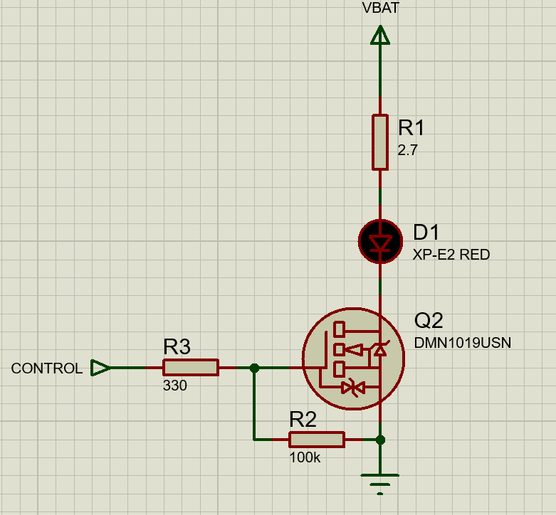
When you use a logic level MOSFET hooked to a microcontroller for switching power, you should add TWO resistors as a matter of habit.
The first is a high value between the gate and the source (usually ground). This is mentioned in the rant article. This is mandatory because it ensures that the gate is held discharged when nothing else is happening. If the gate pin is left floating, it will develop enough of a voltage by itself to at least partially turn on the MOSFET and that is bad not only because whatever it is switching on will be switched on, but also because it is usually in a partial state so looks like a resistor that is getting hotter by the second. If you think this won’t happen because the output pin from the microcontroller is always set to be output and will be driving either low or high then you need to remember what happens when a microcontroller is put into reset either by a programming tool or by some glitch in the rest of the circuit: the pin will go to a high impedance input state. Depending on who’s chip you are playing with, there may or may not be internal pull up or pull down resistors on the pin enabled by default in reset. A default pull up resistor will help to turn the MOSFET on!
If the micro pin does *not* have default pull up resistors (so is properly floating), or else has internal default pull-downs instead, then I’ll use about 100kOhm for this.
If the micro has pull-ups, then I’ll use 10kOhm or 4.7kOhm to make sure my resistor wins the battle for control over the gate.
The second resistor is in series between the microcontroller pin and the gate.
Without it, the output pin will experience (momentarily) something resembling a dead short to ground when the pin goes high. So for some extremely brief amount of time, the pin *may* experience an output current of many amps.
A series resistor should be sized to ensure the output current into a dead short to ground doesn’t exceed the pin’s rated output current.
For example, the pins on an ESP32 are supposedly rated to max 12mA at 3.3V, so I would use a series resistor of at least 3.3/0.012=275ohm. 270ohm would be close enough but 330ohm would give some safety margin.
These two resistors go on my MOSFETs every single time they are connected to a microcontroller.
The rules are different if the MOSFETs are connected to other devices like switching regulators or specific MOSFET driver chips (designed to handle high gate currents and takes the load of the microcontroller).

Paul Hutchison
Great reading, thanks Andrew. Lots of little points I hadn't considered. I'm on the end of the spectrum nearer "which MOSFET are SparkFun or others currently selling for logic level switching? Right - order that one!". I get more than a little confused trying to square up all those little variables you talk about when looking at the datasheets.
It would be nice if someone (who wasn't trying to sell me something) put together a list of say a dozen good, cheap, available MOSFETs for the most common tasks. And keep that list up to date...
kris
Thanks Andrew that is very useful info, and i see what you mean by too
many variables.
i haven't put a resistor on the uM pin and yes, during boot some
channels light up faster than others (takes about a second to settle down).
And when i had it on the bread board i did notice that i could toggle
the mosfets simply by momentarily touching the gate to 5v and after
disconnecting it kept running.
i'll redo the circuit and put a resistor between the uM the gate and
ground. The one you mention should be in series i don't really
understand exactly where it should be (in front of the leg that goes to
the 10k to ground or after or does it not matter? and if the uM has
internal pull up and pull down is that still required?
thanks!
Kris
On 26/06/17 07:02, Paul Hutchison wrote:
>
> Great reading, thanks Andrew. Lots of little points I hadn't
> considered. I'm on the end of the spectrum nearer "which MOSFET are
> SparkFun or others currently selling for logic level switching? Right
> - order that one!". I get more than a little confused trying to
> square up all those little variables you talk about when looking at
> the datasheets.
>
> It would be nice if someone (who wasn't trying to sell me something)
> put together a list of say a dozen good, cheap, available MOSFETs for
> the most common tasks. And keep that list up to date...
>
>
> On Mon., 26 Jun. 2017, 12:59 am Andrew Larkin,
> instead, then I’ll use about 100kOhm for this.
>
>
>
> If the micro has pull-ups, then I’ll use 10kOhm or 4.7kOhm to make
> sure my resistor wins the battle for control over the gate.
>
>
>
> The second resistor is in series between the microcontroller pin
> and the gate.
>
>
>
> Without it, the output pin will experience (momentarily) something
> resembling a dead short to ground when the pin goes high. So for
>
>
>
> A series resistor should be sized to ensure the output current
> into a dead short to ground doesn’t exceed the pin’s rated output
> current.
>
>
>
> For example, the pins on an ESP32 are supposedly rated to max 12mA
> at 3.3V, so I would use a series resistor of at least
> 3.3/0.012=275ohm. 270ohm would be close enough but 330ohm would
> give some safety margin.
>
>
>
> These two resistors go on my MOSFETs every single time they are
> connected to a microcontroller.
>
>
>
> The rules are different if the MOSFETs are connected to other
> devices like switching regulators or specific MOSFET driver chips
> (designed to handle high gate currents and takes the load of the
> microcontroller).
>
>
>
> <mailto:sydney-h...@googlegroups.com>
> [mailto:sydney-h...@googlegroups.com
> <mailto:sydney-h...@googlegroups.com>] *On Behalf Of *Kris
> *Sent:* Sunday, 25 June 2017 7:48 PM
>
>
> *To:* sydney-h...@googlegroups.com
> <mailto:sydney-h...@googlegroups.com>
> *Subject:* Re: [RnD] do not tip
>
>
> Cool, when you said adequate I thought you were hinting there was
> a better one for 3.3v
>
>
> *From:*andrewl <and...@arcadius.com.au
> <mailto:and...@arcadius.com.au>>
> *Sent:* 25 June 2017 17:00:08 GMT+10:00
> *To:* "sydney-h...@googlegroups.com
> <mailto:sydney-h...@googlegroups.com>"
> <sydney-h...@googlegroups.com
> <mailto:sydney-h...@googlegroups.com>>
> *Subject:* Re: [RnD] do not tip
>
>
> The one I mentioned is good for 3.3V.
>
>
>
>
>
> Sent from my Samsung Galaxy smartphone.
>
> -------- Original message --------
>
>
> Date: 25/06/2017 2:24 pm (GMT+10:00)
>
> To: sydney-h...@googlegroups.com
> <mailto:sydney-h...@googlegroups.com>.
> https://groups.google.com/group/sydney-hackspace.
> > For more options, visit https://groups.google.com/d/optout.
> >
>
>
> --
> Sent from my Android device with K-9 Mail. Please excuse my brevity.
>
> --
> You received this message because you are subscribed to the Google
> Groups "Robots & Dinosaurs" group.
> To unsubscribe from this group and stop receiving emails from it,
> send an email to sydney-hackspa...@googlegroups.com
> <mailto:sydney-h...@googlegroups.com>.
> For more options, visit https://groups.google.com/d/optout.
>
> --
> You received this message because you are subscribed to the Google
> Groups "Robots & Dinosaurs" group.
> To unsubscribe from this group and stop receiving emails from it, send
> an email to sydney-hackspa...@googlegroups.com
Andrew Larkin
From a current project...
-----Original Message-----
From: sydney-h...@googlegroups.com [mailto:sydney-h...@googlegroups.com] On Behalf Of kris
Sent: Monday, 26 June 2017 10:00 AM
To: sydney-h...@googlegroups.com
Subject: Re: [RnD] do not tip
i think that's the trick, keeping it up to date!
To unsubscribe from this group and stop receiving emails from it, send an email to sydney-hackspa...@googlegroups.com.
To post to this group, send email to sydney-h...@googlegroups.com.
Andrew Larkin
Mathematically, the other arrangement should give a slightly higher drive voltage to the gate. With a 3.3V MCU and resistor values 330 and 10k, the difference seen by the MOSFET is 0.105V.
As we are so far past the threshold voltage it won't make much difference.
-----Original Message-----
From: sydney-h...@googlegroups.com [mailto:sydney-h...@googlegroups.com] On Behalf Of kris
Sent: Monday, 26 June 2017 10:00 AM
To post to this group, send email to sydney-h...@googlegroups.com.
kris
and if you (or any members) have thoughts about what components (beyond
the usual arduino fare) the space should keep in stock please don't
hesitate to add to this thread.
bear in mind that they should be super general purpose, and not EOL or
nearing EOL.
Kris