Just wanting to check this idea about RPI GPIO

shykitten55
Alas the RPI isn't quite as good with GPIO as the Arduino, but that's how it is.
I have a RPZ (W) and it needs its GPIO pins applied to use.
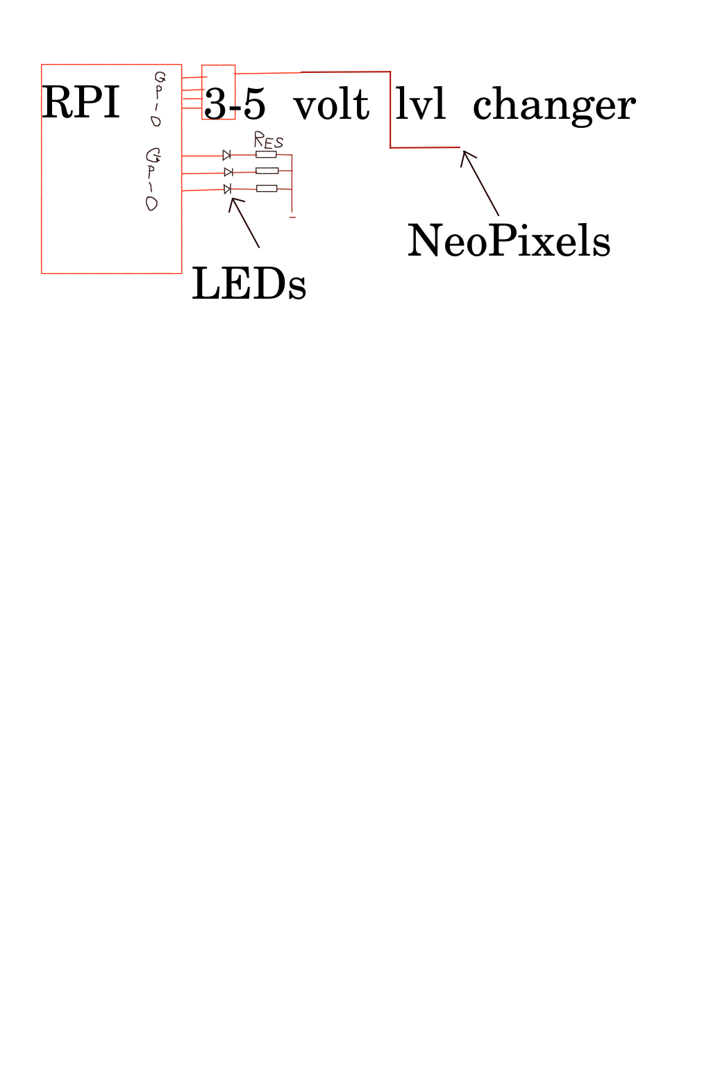
(See attached)
Sorry for the messy layout.
I have a 4 channel level changer and shall put that on a GPIO pin to drive some NeoPixels.
Only 1 channel is needed/used just now, but..... The future: Who knows.
Also there will be 3 LEDs - maybe more - driven from the GPIO pins.
(I know: shame on me) But I can't remember if it is better to sink or source the pins.
IE: The GPIO to the anode of the LED, or cathode.
I'm also not 100% sure about the resistor value, but I'm not at that stage yet.
Would it be better to drive a bunch of UJT/FETs to drive the LEDs?
The next "problem" is power.
Granted I can't suck a lot of power from the RPI. But as they use the u-USB plugs for power, that has me a bit stumped.
Arduinos use those 2.1mm plugs and that makes power easier to set up if external device power is also needed.
So the "plan" is I get a good 5v supply. Jaycar. 5v 3A. But they have Arduino connectors, not u-USB. But anyway.....
So that goes into the project's box.
From there, it will be fanned out to the RPI and the other things. (eg: Level converter)
I'm also (maybe) wanting a buzzer to be powered from a GPIO pin. I'm guessing that WILL need a UJT/FET to drive it.
Oh, and I have a small 5v stereo AMP. Tiny-winy board. L/R input; 5v input and L/R output.
Small speakers to be driven. That will be from the audio out on the RPI.
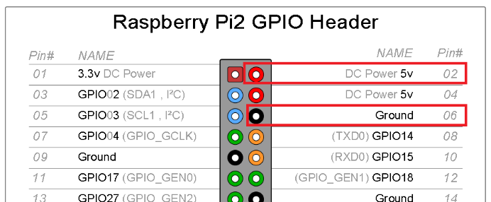
How do I power the PI?
Must I use the u-USB, or can I send power to it via the GPIO? (Kind of like the Arduino nano that I have done.)
I'll stop there, as I am worried I am digging a big/deep hole for myself.
Thanks again to all replies.

John Teague
--
You received this message because you are subscribed to the Google Groups "Robots & Dinosaurs" group.
To unsubscribe from this group and stop receiving emails from it, send an email to sydney-hackspa...@googlegroups.com.
To post to this group, send email to sydney-h...@googlegroups.com.
Visit this group at https://groups.google.com/group/sydney-hackspace.
For more options, visit https://groups.google.com/d/optout.
<Desired RPI outputs.png>
Cat
John.
To unsubscribe from this group and stop receiving emails from it, send an email to sydney-hackspace+unsubscribe@googlegroups.com.
To post to this group, send email to sydney-hackspace@googlegroups.com.
Visit this group at https://groups.google.com/group/sydney-hackspace.
For more options, visit https://groups.google.com/d/optout.
<Desired RPI outputs.png>--
You received this message because you are subscribed to a topic in the Google Groups "Robots & Dinosaurs" group.
To unsubscribe from this topic, visit https://groups.google.com/d/topic/sydney-hackspace/9Brxqk_MOwY/unsubscribe.
To unsubscribe from this group and all its topics, send an email to sydney-hackspace+unsubscribe@googlegroups.com.
To post to this group, send email to sydney-hackspace@googlegroups.com.

Aaron Power
Everything you read on the Pi will recommend that you power it by the micro-USB port. That's the safest way to do it.
You can power it through the GPIO header using a 5V supply on pins 2 and 4 (see below). **BUT** this puts the power on to the Pi after any circuit protection that's built in to the Pi board. So if anything goes wrong with your power supply, it will most likely instantly fry your Pi.
Having said that, this is the way I typically power most Pi
projects, especially if you are making some sort of HAT style
add-on board. You just need to be careful that you use a decent
power supply, with good regulation - and understand and accept if
anything goes wrong, you're going to be buying a new Pi :-)
Cat
John.
To unsubscribe from this group and stop receiving emails from it, send an email to sydney-hackspace+unsubscribe@googlegroups.com.
To post to this group, send email to sydney-hackspace@googlegroups.com.
Visit this group at https://groups.google.com/group/sydney-hackspace.
For more options, visit https://groups.google.com/d/optout.
<Desired RPI outputs.png>
--
You received this message because you are subscribed to the Google Groups "Robots & Dinosaurs" group.
To unsubscribe from this group and stop receiving emails from it, send an email to sydney-hackspace+unsubscribe@googlegroups.com.
To post to this group, send email to sydney-hackspace@googlegroups.com.
Visit this group at https://groups.google.com/group/sydney-hackspace.
For more options, visit https://groups.google.com/d/optout.
--
You received this message because you are subscribed to a topic in the Google Groups "Robots & Dinosaurs" group.
To unsubscribe from this topic, visit https://groups.google.com/d/topic/sydney-hackspace/9Brxqk_MOwY/unsubscribe.
To unsubscribe from this group and all its topics, send an email to sydney-hackspace+unsubscribe@googlegroups.com.
To post to this group, send email to sydney-hackspace@googlegroups.com.
Aaron Power
Most USB cables I've ever cut in to (even the cheap ones) use red and black for the 5V power. It is meant to be green and white for the data (I think?) but I've seen other colours used.
Basically red and black = power; other two = data <== But of course I would recommend you test before plugging it in.
Unless you are using some insanely bright, high powered LED and buzzer, I would just drive them straight off the Pi GPIO pins. You just have to remember that you are driving them from 3.3V rather than 5V, so the resistor values will be smaller.
Aaron
To unsubscribe from this group and stop receiving emails from it, send an email to sydney-hackspa...@googlegroups.com.
To post to this group, send email to sydney-h...@googlegroups.com.
Cat

Kris
With it powered up
Use a meter to confirm red is 5 and black is 0 going into the connector. Find something you don't care about that charges via USB and test. Not something that would like data.
From: Cat <fuzzywu...@gmail.com>
Sent: 9 May 2018 21:48:06 GMT+10:00
To: sydney-h...@googlegroups.com
Subject: Re: [RnD] Just wanting to check this idea about RPI GPIO
Sent from my Breville Talkie Toaster with K-9 Mail. Please excuse my brevity.
Jess Mayo
I really like the idea of using a powered USB hub, btw. It gives you a common point to connect to everything with a usb port in a project in addition to providing a common power distribution point. And if you don't want to open up the USB hub's case to solder to the insides, then soldering your own full-size USB plugs is a whole lot easier than messing with micro USB :)
I might use this idea myself sometime. :)
-- Jess
(Everything with a grin :)
Cat

andrewl
To post to this group, send email to sydney-h...@googlegroups.com.