ESP8266 First Examples and Advices [DHT,DS18B20,LDR,PWM,EMONLIB]

Juan Pinto
- Install Arduino 1.6.4 from the Arduino website.
- Start Arduino and open Perferences window.
- Enter
http://arduino.esp8266.com/package_esp8266com_index.jsoninto Additional Board Manager URLs field. You can add multiple URLs, separating them with commas. - Open Boards Manager from Tools > Board menu and install esp8266 platform (and don't forget to select your ESP8266 board from Tools > Board menu after installation).
 // Configure the framework
#include "bconf/MCU_ESP8266.h"              // Load the code directly on the ESP8266
#include "conf/Gateway.h"                   // The main node is the Gateway, we have just one node
#include "conf/DynamicAddressing.h"         // Use dynamic addressing
//#include "conf/DisableEEPROM.h"


// Define the WiFi name and password
#define WIFICONF_INSKETCH
#define WiFi_SSID               "SSID"
#define WiFi_Password           "PASSWORD"


// Include framework code and libraries
//#include <SPI.h>
#include <ESP8266WiFi.h>
#include <EEPROM.h>
#include "Souliss.h"


// Include and Configure DHT11 SENSOR
#include "DHT.h"
#define DHTPIN 13     // what pin we're connected to
#define DHTTYPE DHT11   // DHT 11
DHT dht(DHTPIN, DHTTYPE, 15);


// This identify the number of the LED logic
#define TEMPERATURE         0
#define HUMIDITY            2


void setup()
{
    Initialize();

    Serial.begin(115200);
    Serial.println("DHTxx test!");
    dht.begin();

    // Connect to the WiFi network and get an address from DHCP
    Setup_ESP8266();
    SetAsGateway(myvNet_esp8266);       // Set this node as gateway for SoulissApp
    SetAddressingServer();
    // This node will serve all the others in the network providing an address

    Set_Temperature(TEMPERATURE);
    Set_Humidity(HUMIDITY);
}


void loop()
{
    // Here we start to play
    EXECUTEFAST() {
        UPDATEFAST();

        FAST_2110ms()
        {
           Logic_Temperature(TEMPERATURE);
           Logic_Humidity(HUMIDITY);
        }

        // Here we handle here the communication with Android
        FAST_GatewayComms();
    }
    EXECUTESLOW() {
 UPDATESLOW();


            SLOW_10s() {
   // Read temperature and humidity from DHT every 10 seconds
           float h = dht.readHumidity();
              // Read temperature as Celsius
              float t = dht.readTemperature();

              // Check if any reads failed and exit early (to try again).
              if (isnan(h) || isnan(t) || isnan(f)) {
                Serial.println("Failed to read from DHT sensor!");
                //return;
              }

              Serial.print("Humidity: ");
              Serial.print(h);
              Serial.print(" %\t");
              Serial.print("Temperature: ");
              Serial.print(t);
              Serial.print(" *C ");


             Souliss_ImportAnalog(memory_map, TEMPERATURE, &t);
            Souliss_ImportAnalog(memory_map, HUMIDITY, &h);
            }
    }
} // Configure the framework
#include "bconf/MCU_ESP8266.h" // Load the code directly on the ESP8266
#include "conf/Gateway.h" // The main node is the Gateway, we have just one node
#include "conf/DynamicAddressing.h" // Use dynamic addressing
// Define the WiFi name and password
#define WIFICONF_INSKETCH
#define WiFi_SSID "SSID"
#define WiFi_Password "PASSWORD"
// Include framework code and libraries
#include <ESP8266WiFi.h>
#include <EEPROM.h>
#include "Souliss.h"
// This identify the number of the SLOT logic
#define DALLAS 0
#include <OneWire.h>
#include <DallasTemperature.h>
#define DALLASPIN 4 //Se declara el pin donde se conectará la DATA
OneWire ourWire(DALLASPIN); //Se establece el pin declarado como bus para la comunicación OneWire
DallasTemperature sensors(&ourWire); //Se instancia la librería DallasTemperature
void setup()
{
Initialize();
Serial.begin(115200);
sensors.begin(); //Se inician los sensores DS18B20
// Connect to the WiFi network and get an address from DHCP
Setup_ESP8266();
SetAsGateway(myvNet_esp8266); // Set this node as gateway for SoulissApp
Set_Temperature(DALLAS);
}
void loop()
{
EXECUTEFAST() {
UPDATEFAST();
FAST_910ms() {
// Acquire temperature from the microcontroller ADC
sensors.requestTemperatures(); //Prepara el sensor para la lectura
float dallas = sensors.getTempCByIndex(0);
Souliss_ImportAnalog(memory_map, DALLAS, &dallas);
}
FAST_2110ms()
{
Logic_Temperature(DALLAS);
}
// Here we handle here the communication with Android
FAST_GatewayComms();
}
} - Start Arduino and Load the Arduino as ISP example to an Arduino (any of them)
- Connect to the Attiny following this scheme:
Open Perferences window.- Enter
https://raw.githubusercontent.com/damellis/attiny/ide-1.6.x-boards-manager/package_damellis_attiny_index.jsoninto Additional Board Manager URLs field. You can add multiple URLs, separating them with commas. Note: I've an error if I put the esp and the attiny separated by comma, but you can add the attiny and when its programmed leave only the ESP one. - Open Boards Manager from Tools > Board menu and install attiny platform (and don't forget to select your Attiny 1mhz Internal Clock board from Tools > Board menu after installation).
- Select on Tools Arduino as ISP
- Load this sketch to the Attiny:
- Sketch Attiny:

#include <SoftwareSerial.h>
#include "EmonLib.h"             // Include Emon Library
EnergyMonitor emon1;             // Create an instance


SoftwareSerial TinySerial(3, 4); // RX, TX
#define LED 1
#define CT  A1


void setup()
{
  // Open serial communications and let us know we are connected
 TinySerial.begin(9600);  // SET TO 1200 ON RECEIVER, I DONT KNOW WHY
 pinMode(LED, OUTPUT);
 emon1.current(CT, 10);       // Current: input pin, calibration.
}


void loop()
{
  float current = emon1.calcIrms(1480);
  TinySerial.print(current);
  delay(100);
  digitalWrite(LED,!digitalRead(LED));
}

Where RVD = 10kohm and Burden is 220ohm.
// Configure the framework
#include "bconf/MCU_ESP8266.h" // Load the code directly on the ESP8266
#include "conf/Gateway.h" // The main node is the Gateway, we have just one node
#include "conf/DynamicAddressing.h" // Use dynamic addressing
// Define the WiFi name and password
#define WIFICONF_INSKETCH
#define WiFi_SSID "SSID"
#define WiFi_Password "PASSWORD"
// Include framework code and libraries
#include <ESP8266WiFi.h>
#include <EEPROM.h>
#include "Souliss.h"
// This identify the number of the LED logic
#define CURRENT 0
#define WATTS 2
void setup()
{
Initialize();
Serial.begin(9600);
Serial1.begin(115200);
// Connect to the WiFi network and get an address from DHCP
Setup_ESP8266();
SetAsGateway(myvNet_esp8266); // Set this node as gateway for SoulissApp
// This node will serve all the others in the network providing an address
Set_Current(CURRENT);
Set_Power(WATTS);
}
void loop()
{
EXECUTEFAST() {
UPDATEFAST();
FAST_510ms() {
Logic_Current(CURRENT);
Logic_Power(WATTS);
}
FAST_710ms() {
float current = 0;
if(Serial.available()){
float current = Serial.parseFloat();
Serial1.println(current);
Souliss_ImportAnalog(memory_map, CURRENT, ¤t);
float watt = current*230;
Souliss_ImportAnalog(memory_map, WATTS, &watt);
}
}
// Here we handle here the communication with Android
FAST_GatewayComms();
}
} // Configure the framework
#include "bconf/MCU_ESP8266.h" // Load the code directly on the ESP8266
#include "conf/Gateway.h" // The main node is the Gateway, we have just one node
#include "conf/DynamicAddressing.h" // Use dynamic addressing
// Define the WiFi name and password
#define WIFICONF_INSKETCH
#define WiFi_SSID "SSID"
#define WiFi_Password "PASSWORD"
// Include framework code and libraries
#include <ESP8266WiFi.h>
#include <EEPROM.h>
#include "Souliss.h"
// This identify the number of the LED logic
#define LDR 0
#define SensorLDR_pin A0
//NUEVA FUNCION PARA LEER LDR Y PASARLO A KLUX:
// Light calibration data
// out[] holds the values wanted in lux/10
static const unsigned int out[] = { 7, 30, 45, 65, 150, 300, 450, 2100, 13000}; // x10 //ULTIMO VALOR REFERENCIA
static const unsigned int in[] = { 100, 350, 430, 500, 680, 780, 950, 1005, 1024 }; // 0 - 1024
void setup()
{
Initialize();
Serial.begin(115200);
// Connect to the WiFi network and get an address from DHCP
Setup_ESP8266();
SetAsGateway(myvNet_esp8266); // Set this node as gateway for SoulissApp
// This node will serve all the others in the network providing an address
Set_T54(LDR);
}
void loop()
{
EXECUTEFAST() {
UPDATEFAST();
FAST_2110ms()
{
Logic_T54(LDR);
}
FAST_7110ms()
{
float ldr_read = get_lux(in, out, 16)/10.0; //ORIGINAL
if (ldr_read == 0) ldr_read = 0.01;
Souliss_ImportAnalog(memory_map, LDR, &ldr_read);
}
// Here we handle here the communication with Android
FAST_GatewayComms();
}
}
//////////////////////////////////////////////////////////////////////////////
// Calculate lux based on rawADC reading from LDR returns value in lux/10
//////////////////////////////////////////////////////////////////////////////
int get_lux(const unsigned int* _in, const unsigned int* _out, byte size)
{
// take care the value is within range
// val = constrain(val, _in[0], _in[size-1]);
int val = analogRead(A0);
Serial.print("AnalogRead: ");
Serial.println(val);
if (val <= _in[0]) return _out[0];
if (val >= _in[size-1]) return _out[size-1];
// search right interval
byte pos = 1; // _in[0] allready tested
while(val > _in[pos]) pos++;
// this will handle all exact "points" in the _in array
if (val == _in[pos]) return _out[pos];
// interpolate in the right segment for the rest
return map(val, _in[pos-1], _in[pos], _out[pos-1], _out[pos]);
}// Configure the framework
#include "bconf/MCU_ESP8266.h" // Load the code directly on the ESP8266
#include "conf/Gateway.h" // The main node is the Gateway, we have just one node
#include "conf/DynamicAddressing.h" // Use dynamic addressing
// Define the WiFi name and password
#define WIFICONF_INSKETCH
#define WiFi_SSID "SSID"
#define WiFi_Password "PASSWORD"
// Include framework code and libraries
#include <ESP8266WiFi.h>
#include <EEPROM.h>
#include "Souliss.h"
// This identify the number of the SLOT logic
#define LEDPWM 9
//PWM pin
#define LEDPWMP 5
void setup()
{
Initialize();
Serial.begin(115200);
// Connect to the WiFi network and get an address from DHCP
Setup_ESP8266();
SetAsGateway(myvNet_esp8266); // Set this node as gateway for SoulissApp
// This node will serve all the others in the network providing an address
Set_DimmableLight(LEDPWM);
pinMode(LEDPWMP, OUTPUT);
}
void loop()
{
EXECUTEFAST() {
UPDATEFAST();
FAST_50ms() { // We process the logic and relevant input and output every 50 milliseconds
Logic_DimmableLight(LEDPWM);
analogWrite(LEDPWMP, mOutput(LEDPWM+1)*4);
}
// Here we handle here the communication with Android
FAST_GatewayComms();
}
EXECUTESLOW() {
UPDATESLOW();
SLOW_10s() { // Read temperature and humidity from DHT every 110 seconds
Timer_DimmableLight(LEDPWM);
}
}
} Juan Pinto

Lesjaw Ardi™ ♂
--
You received this message because you are subscribed to the Google Groups "souliss" group.
To unsubscribe from this group and stop receiving emails from it, send an email to souliss+u...@googlegroups.com.
To post to this group, send email to sou...@googlegroups.com.
To view this discussion on the web visit https://groups.google.com/d/msgid/souliss/9ab76cdf-bf56-49b4-9c48-c3e2b23c9c16%40googlegroups.com.
For more options, visit https://groups.google.com/d/optout.

Di Maio, Dario
Hi Juan,
A lot of useful information here!
Please consider that the reference branch is now friariello and friariello-porting, cause have been merged.
Thanks,
Dario.
From Mobile.
Di Maio, Dario
/**************************************************************************
    Souliss - Hello World

    This is the basic example, control one LED via a push-button or Android
    using SoulissApp (get it from Play Store).

    Run this code on one of the following boards:
      - ESP8266 as SoC

***************************************************************************/

// Configure the framework
#include "bconf/MCU_ESP8266.h"
#include "conf/Gateway.h"

/*
  If you are using W5200 or ENC28J60, you just need to  change
  the #include "conf/ethW5100.h" with   #include "conf/ethW5200.h"
  or #include "conf/ethENC28J60.h"

  This assume that your SPI Chip Select (CS) is on pin 10 as in
  most of the Ethernet shield.
*/

// Include framework code and libraries
#include <SPI.h>
#include "Souliss.h"

// This identify the number of the LED logic
#define MYLEDLOGIC          0

// Define the network configuration according
// to your router settings
uint8_t ip_address[4]  = {192, 168, 1, 77};
uint8_t subnet_mask[4] = {255, 255, 255, 0};
uint8_t ip_gateway[4]  = {192, 168, 1, 1};
#define Gateway_address 77
#define myvNet_address  ip_address[3]
#define myvNet_subnet   0xFF00
#define myvNet_supern   Gateway_address

void setup()
{
    Initialize();

     // Set network parameters
    Souliss_SetIPAddress(ip_address, subnet_mask, ip_gateway);
    SetAsGateway(myvNet_address);

    // Define a simple LED light logic
    Set_SimpleLight(MYLEDLOGIC);

    // We connect a pushbutton between 5V and pin2 with a
    // pulldown resistor between pin2 and GND, the LED is
    // connected to pin9 with a resistor to limit the
    // current amount
    pinMode(2, INPUT);   // Hardware pulldown required
    pinMode(9, OUTPUT);  // Power the LED
}

void loop()
{
    // Here we start to play
    EXECUTEFAST() {
        UPDATEFAST();

        // We process the logic and relevant input
        // and output every 50 milliseconds
        FAST_50ms() {
            // Use the pin2 as ON/OFF toggle command
            DigIn(2, Souliss_T1n_ToggleCmd, MYLEDLOGIC);

            // Drive the LED as per command
            Logic_SimpleLight(MYLEDLOGIC);

            // Use the pin9 to give power to the LED according to the logic
            DigOut(9, Souliss_T1n_Coil, MYLEDLOGIC);
        }

        // Here we handle here the communication
        FAST_GatewayComms();

    }
}
Juan Pinto

dcarvetta
Juan Pinto
// NOTE: For working with a faster chip, like an Arduino Due or Teensy, you// might need to increase the threshold for cycle counts considered a 1 or 0.// You can do this by passing a 3rd parameter for this threshold. It's a bit// of fiddling to find the right value, but in general the faster the CPU the// higher the value. The default for a 16mhz AVR is a value of 6. For an// Arduino Due that runs at 84mhz a value of 30 works.// Example to initialize DHT sensor for Arduino Due:
And the value 15 is get from https://github.com/esp8266/Arduino Section: Other libraries (not included with the IDE): DHT11 - initialize DHT as follows: |
Di Maio, Dario
--
You received this message because you are subscribed to the Google Groups "souliss" group.
To unsubscribe from this group and stop receiving emails from it, send an email to souliss+u...@googlegroups.com.
To post to this group, send email to sou...@googlegroups.com.
To view this discussion on the web visit https://groups.google.com/d/msgid/souliss/6191d6d0-c471-4af8-affa-2f4a1dfef9c8%40googlegroups.com.
Juan Pinto
--
You received this message because you are subscribed to a topic in the Google Groups "souliss" group.
To unsubscribe from this topic, visit https://groups.google.com/d/topic/souliss/1kMAltPB2ME/unsubscribe.
To unsubscribe from this group and all its topics, send an email to souliss+u...@googlegroups.com.
To post to this group, send email to sou...@googlegroups.com.
To view this discussion on the web visit https://groups.google.com/d/msgid/souliss/CAKGhMPJfmoXKfHCtsoDs5mqwx927TnizJNWtgbLHYjCgjjpDuQ%40mail.gmail.com.
Juan Pinto
In file included from F:\Mis Documentos\Arduino\___arduino-1.6.4\libraries\souliss/frame/vNet/vNet.h:52:0,
                 from F:\Mis Documentos\Arduino\___arduino-1.6.4\libraries\souliss/Souliss.h:42,
                 from sketch_may26a.ino:27:
F:\Mis Documentos\Arduino\___arduino-1.6.4\libraries\souliss/frame/vNet/drivers/mcu_esp8266/ethESP8266/vNetDriver_eth.h:33:21: fatal error: WiFiUdp.h: No such file or directory
#include "WiFiUdp.h"f:\Mis Documentos\Arduino\___arduino-1.6.4\libraries\WiFi\src\// Define the WiFi name and password
#define WIFICONF_INSKETCH
#define WiFi_SSID "SSID"
#define WiFi_Password "PASSWORD" SetAsGateway(myvNet_esp8266);
GetIPAddress();
SetAsGateway(myvNet_dhcp);Juan Pinto
// Configure the framework
#include "bconf/MCU_ESP8266.h" // Load the code directly on the ESP8266
#include "conf/Gateway.h" // The main node is the Gateway, we have just one node
#include "conf/DynamicAddressing.h" // Use dynamic addressing
// Define the WiFi name and password
#define WIFICONF_INSKETCH
#define WiFi_SSID               "SSID"
#define WiFi_Password           "PASSWORD"
// Include framework code and libraries
#include <ESP8266WiFi.h>
#include <EEPROM.h>
#include "Souliss.h"
// This identify the number of the LED logic
#define PRESSURE0 0
#define BMP180TEMP 2
// SDA and SCL pins can be configured, you need to edit SFE_BMP180/SFE_BMP180.cpp line 38. Preconfigured at 14, 12.
#include <SFE_BMP180.h>
#include <Wire.h>
#define ALTITUDE 20.0 // Altitude of reading location in meters
// You will need to create an SFE_BMP180 object, here called "pressure":
SFE_BMP180 pressure;
void setup()
{
Initialize();
Serial1.begin(115200);
// Connect to the WiFi network and get an address from DHCP
GetIPAddress();
SetAsGateway(myvNet_dhcp); // Set this node as gateway for SoulissApp
if (pressure.begin())
Serial1.println("BMP180 init success");
else
{
// Oops, something went wrong, this is usually a connection problem,
// see the comments at the top of this sketch for the proper connections.
Serial1.println("BMP180 init fail\n\n");
}
}
void loop()
{
EXECUTEFAST() {
UPDATEFAST();
// Here we handle here the communication with Android
        FAST_GatewayComms();
    }
    EXECUTESLOW() {
 UPDATESLOW();


            SLOW_10s() {  // Read temperature and humidity from DHT every 110 seconds
              Souliss_GetPressure_BMP180(PRESSURE0,BMP180TEMP);

            }
      }
}


/***************************************************************************/
/*                         BMP180 I2C READING FUNCTION                     */
/***************************************************************************/
float Souliss_GetPressure_BMP180(uint8_t SLOT_PRESSURE, uint8_t SLOT_TEMPERATURE){

  boolean DEBUG_PRESSURE = 0;

  char status;
  double T,P,p0,a;


  // Loop here getting pressure readings every 10 seconds.


  // If you want sea-level-compensated pressure, as used in weather reports,
  // you will need to know the altitude at which your measurements are taken.
  // We're using a constant called ALTITUDE in this sketch:

  if(DEBUG_PRESSURE){
    Serial1.println();
    Serial1.print("provided altitude: ");
    Serial1.print(ALTITUDE,0);
    Serial1.print(" meters, ");
    Serial1.print(ALTITUDE*3.28084,0);
    Serial1.println(" feet");
  }
  // If you want to measure altitude, and not pressure, you will instead need
  // to provide a known baseline pressure. This is shown at the end of the sketch.


  // You must first get a temperature measurement to perform a pressure reading.

  // Start a temperature measurement:
  // If request is successful, the number of ms to wait is returned.
  // If request is unsuccessful, 0 is returned.


  status = pressure.startTemperature();
  if (status != 0)
  {
    // Wait for the measurement to complete:
    delay(status);


    // Retrieve the completed temperature measurement:
    // Note that the measurement is stored in the variable T.
    // Function returns 1 if successful, 0 if failure.


    status = pressure.getTemperature(T);
    if (status != 0)
    {
      if(DEBUG_PRESSURE){
        // Print out the measurement:
        Serial1.print("temperature: ");
        Serial1.print(T,2);
        Serial1.print(" deg C, ");
        Serial1.print((9.0/5.0)*T+32.0,2);
        Serial1.println(" deg F");
      }
      // Start a pressure measurement:
      // The parameter is the oversampling setting, from 0 to 3 (highest res, longest wait).
      // If request is successful, the number of ms to wait is returned.
      // If request is unsuccessful, 0 is returned.


      status = pressure.startPressure(3);
      if (status != 0)
      {
        // Wait for the measurement to complete:
        delay(status);


        // Retrieve the completed pressure measurement:
        // Note that the measurement is stored in the variable P.
        // Note also that the function requires the previous temperature measurement (T).
        // (If temperature is stable, you can do one temperature measurement for a number of pressure measurements.)
        // Function returns 1 if successful, 0 if failure.


        status = pressure.getPressure(P,T);
        if (status != 0)
        {
          if(DEBUG_PRESSURE){
            // Print out the measurement:
            Serial1.print("absolute pressure: ");
            Serial1.print(P,2);
            Serial1.print(" mb, ");
            Serial1.print(P*0.0295333727,2);
            Serial1.println(" inHg");
          }
          // The pressure sensor returns abolute pressure, which varies with altitude.
          // To remove the effects of altitude, use the sealevel function and your current altitude.
          // This number is commonly used in weather reports.
          // Parameters: P = absolute pressure in mb, ALTITUDE = current altitude in m.
          // Result: p0 = sea-level compensated pressure in mb


          p0 = pressure.sealevel(P,ALTITUDE); // we're at 1655 meters (Boulder, CO)
          if(DEBUG_PRESSURE){
            Serial1.print("relative (sea-level) pressure: ");
            Serial1.print(p0,2);
            Serial1.print(" mb, ");
            Serial1.print(p0*0.0295333727,2);
            Serial1.println(" inHg");
          }
          // On the other hand, if you want to determine your altitude from the pressure reading,
          // use the altitude function along with a baseline pressure (sea-level or other).
          // Parameters: P = absolute pressure in mb, p0 = baseline pressure in mb.
          // Result: a = altitude in m.


          a = pressure.altitude(P,p0);
          if(DEBUG_PRESSURE){
            Serial1.print("computed altitude: ");
            Serial1.print(a,0);
            Serial1.print(" meters, ");
            Serial1.print(a*3.28084,0);
            Serial1.println(" feet");
          }
          float pressure = p0;
          float temperature = T;
          Souliss_ImportAnalog(memory_map, SLOT_PRESSURE, &pressure);
          Souliss_ImportAnalog(memory_map, SLOT_TEMPERATURE, &temperature);
          return p0;
        }
        else if(DEBUG_PRESSURE) Serial1.println("error retrieving pressure measurement\n");
      }
      else if(DEBUG_PRESSURE) Serial1.println("error starting pressure measurement\n");
    }
    else if(DEBUG_PRESSURE) Serial1.println("error retrieving temperature measurement\n");
  }
  else if(DEBUG_PRESSURE) Serial1.println("error starting temperature measurement\n");

}El lunes, 25 de mayo de 2015, 23:53:20 (UTC+2), Juan Pinto escribió:
...
dcarvetta
In file included from C:\Users\Carvetta\Desktop\ESP8266\arduino-1.6.1-esp8266\arduino-1.6.1\hardware\esp8266com\esp8266\cores\esp8266/Arduino.h:34:0,
                 from C:\Users\Carvetta\Desktop\ESP8266\arduino-1.6.1-esp8266\arduino-1.6.1\hardware\esp8266com\esp8266\libraries\ESP8266WiFi\src/WiFiClient.h:24,
                 from C:\Users\Carvetta\Desktop\ESP8266\arduino-1.6.1-esp8266\arduino-1.6.1\hardware\esp8266com\esp8266\libraries\ESP8266WiFi\src/ESP8266WiFi.h:32,
                 from e08_Hello_ESP8266_test0002_Juan_version.ino:16:
e08_Hello_ESP8266_test0002_Juan_version.ino: In function 'void loop()':
e08_Hello_ESP8266_test0002_Juan_version.ino:78:49: error: 'f' was not declared in this scope
Errore durante la compilazione // Check if any reads failed and exit early (to try again).
             //if (isnan(h) || isnan(t) || isnan(f)) {
             //   Serial.println("Failed to read from DHT sensor!");
             //   return;
// }Juan Pinto
if (isnan(h) || isnan(t) || isnan(f)) { if (isnan(h) || isnan(t) {Lesjaw Ardi™ ♂
Do you need Fahrenheit? If not just remove it..
Remove this || isnan(f)
--
You received this message because you are subscribed to the Google Groups "souliss" group.
To unsubscribe from this group and stop receiving emails from it, send an email to souliss+u...@googlegroups.com.
To post to this group, send email to sou...@googlegroups.com.
To view this discussion on the web visit https://groups.google.com/d/msgid/souliss/96d31787-b78d-40d9-997c-71cd9ef1b01a%40googlegroups.com.
Lesjaw Ardi™ ♂
--
You received this message because you are subscribed to the Google Groups "souliss" group.
To unsubscribe from this group and stop receiving emails from it, send an email to souliss+u...@googlegroups.com.
To post to this group, send email to sou...@googlegroups.com.
To view this discussion on the web visit https://groups.google.com/d/msgid/souliss/b95d5269-e5d5-45ea-92f6-fc1a6cb0686d%40googlegroups.com.
dcarvetta
Juan Pinto
--
You received this message because you are subscribed to a topic in the Google Groups "souliss" group.
To unsubscribe from this topic, visit https://groups.google.com/d/topic/souliss/1kMAltPB2ME/unsubscribe.
To unsubscribe from this group and all its topics, send an email to souliss+u...@googlegroups.com.
To post to this group, send email to sou...@googlegroups.com.
To view this discussion on the web visit https://groups.google.com/d/msgid/souliss/CAJ6Uq_nimKP11KHES_MDDkna07NOwt_dzigGpRfK%2BDx1-BFsyw%40mail.gmail.com.
dcarvetta
Juan Pinto
Juan Pinto
El miércoles, 27 de mayo de 2015, 19:03:40 (UTC+2), dcarvetta escribió:
dcarvetta
Di Maio, Dario
Hi Juan,
could you please update your sketches according to the latest commit? The change is in the setup() function for DHCP.
Please consider that you could now install Souliss for ESP via the Library Manager with target release 7.0.5.
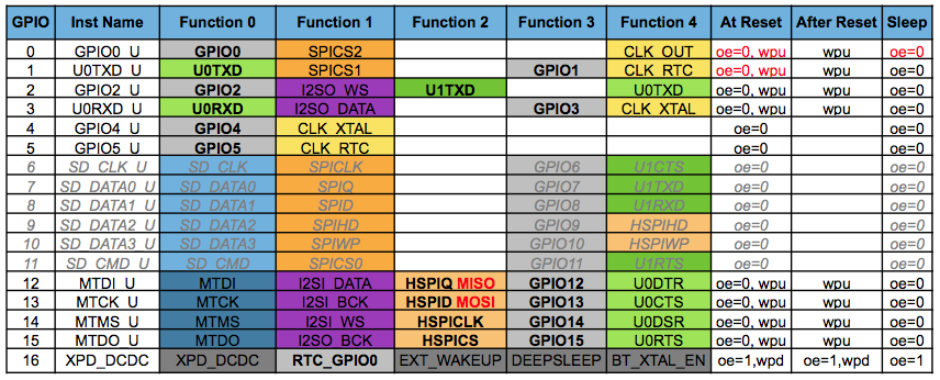
It would be great have also a table of pins that could be used with ESP8266, because isn't clear which one are for SPI, I2C or general purpose.
Dario.
From Mobile.
...
Juan Pinto

--
You received this message because you are subscribed to a topic in the Google Groups "souliss" group.
To unsubscribe from this topic, visit https://groups.google.com/d/topic/souliss/1kMAltPB2ME/unsubscribe.
To unsubscribe from this group and all its topics, send an email to souliss+u...@googlegroups.com.
To post to this group, send email to sou...@googlegroups.com.
To view this discussion on the web visit https://groups.google.com/d/msgid/souliss/CAKGhMPL5S34WPbeGYAEO8sznXQOr2A2Cv0kx%3DW9%2BR_VHkbCecg%40mail.gmail.com.
Di Maio, Dario
Hi Juan,
yes is it :)
What isn't clear for me is the oin functions, I cannot found further details. Have you some read for further understanding?
Thanks,
Dario.
From Mobile.
You received this message because you are subscribed to the Google Groups "souliss" group.
To unsubscribe from this group and stop receiving emails from it, send an email to souliss+u...@googlegroups.com.
To post to this group, send email to sou...@googlegroups.com.
To view this discussion on the web visit https://groups.google.com/d/msgid/souliss/CAN5yH6GXuvMK_TiB1BMXWpqqAqi9jf02pG7-2drSX-htXBP8%2Bg%40mail.gmail.com.
Juan Pinto
To view this discussion on the web visit https://groups.google.com/d/msgid/souliss/CAKGhMPLchyoGiQW_brwCetb-9vpDdNuZmS6npAmJqDcrscXRWA%40mail.gmail.com.
Di Maio, Dario
There are several function for each pin, but I cannot find any docs on functions and how set it.
Dario.
From Mobile.
To view this discussion on the web visit https://groups.google.com/d/msgid/souliss/CAN5yH6EumgzyJNgfRJp3pid_6XRj19OZuABPbbX5y6r%3DE_pxug%40mail.gmail.com.
Juan Pinto
The most usable pin functions are mapped to the macroSPECIAL, so callingpinMode(pin, SPECIAL)will switch that pin in the most usable FUNCTION_X. Those are UART RX/TX on pins 1 - 3, HSPI for pins 12-15 and CLK functions for pins 0, 4 and 5.
...
Di Maio, Dario
I want to learn more on ESP :)
From Mobile.
--
You received this message because you are subscribed to the Google Groups "souliss" group.
To unsubscribe from this group and stop receiving emails from it, send an email to souliss+u...@googlegroups.com.
To post to this group, send email to sou...@googlegroups.com.
To view this discussion on the web visit https://groups.google.com/d/msgid/souliss/bc0d1455-e0ed-4301-a7e1-6324076b2f7f%40googlegroups.com.
Juan Pinto
--
You received this message because you are subscribed to a topic in the Google Groups "souliss" group.
To unsubscribe from this topic, visit https://groups.google.com/d/topic/souliss/1kMAltPB2ME/unsubscribe.
To unsubscribe from this group and all its topics, send an email to souliss+u...@googlegroups.com.
To post to this group, send email to sou...@googlegroups.com.
To view this discussion on the web visit https://groups.google.com/d/msgid/souliss/CAKGhMPLNgPQ%3DtPgnxPegAoZSnA-UHfTacRTrWn3c0-UANUob2w%40mail.gmail.com.
dcarvetta
Di Maio, Dario
--
You received this message because you are subscribed to the Google Groups "souliss" group.
To unsubscribe from this group and stop receiving emails from it, send an email to souliss+u...@googlegroups.com.
To post to this group, send email to sou...@googlegroups.com.
To view this discussion on the web visit https://groups.google.com/d/msgid/souliss/0d364f41-c0fa-4c1a-af71-295d21d92172%40googlegroups.com.
Domenico Carvetta
// Configure the framework
#include "bconf/MCU_ESP8266.h" // Load the code directly on the ESP8266
#include "conf/DynamicAddressing.h"
Di Maio, Dario
--
You received this message because you are subscribed to the Google Groups "souliss" group.
To unsubscribe from this group and stop receiving emails from it, send an email to souliss+u...@googlegroups.com.
To post to this group, send email to sou...@googlegroups.com.
To view this discussion on the web visit https://groups.google.com/d/msgid/souliss/e7f4e643-0247-4fb0-9ab7-33214530be5f%40googlegroups.com.
domenico carvetta
--
You received this message because you are subscribed to a topic in the Google Groups "souliss" group.
To unsubscribe from this topic, visit https://groups.google.com/d/topic/souliss/1kMAltPB2ME/unsubscribe.
To unsubscribe from this group and all its topics, send an email to souliss+u...@googlegroups.com.
To post to this group, send email to sou...@googlegroups.com.
To view this discussion on the web visit https://groups.google.com/d/msgid/souliss/CAKGhMPL13AKUoL3SPcn0tCPb6BE5QN6pbDLLfr5QqOo39QWt8Q%40mail.gmail.com.
Domenico Carvetta
Juan Pinto
| SoftwareSerial TinySerial(3, 4); // RX, TX | |
| #define LED 1 |
| #define CT A1 |
--
You received this message because you are subscribed to a topic in the Google Groups "souliss" group.
To unsubscribe from this topic, visit https://groups.google.com/d/topic/souliss/1kMAltPB2ME/unsubscribe.
To unsubscribe from this group and all its topics, send an email to souliss+u...@googlegroups.com.
To post to this group, send email to sou...@googlegroups.com.
To view this discussion on the web visit https://groups.google.com/d/msgid/souliss/3599fb0b-c395-410f-aed6-a919c013befd%40googlegroups.com.
domenico carvetta
Thanks, which is RX on attiny ? Sede my list.
domenico carvetta
Correction: I mean TX.
Di Maio, Dario
If I'm not wrong, ATtiny has no USART, you need a Software Serial.
Dario.
From Mobile.
carvetta...@gmail.com
Which is the ATtiny tx pin number ?
Inviato da HTC
To unsubscribe from this topic, visit https://groups.google.com/d/topic/souliss/1kMAltPB2ME/unsubscribe.
To unsubscribe from this group and all its topics, send an email to souliss+u...@googlegroups.com.
To post to this group, send email to sou...@googlegroups.com.
Di Maio, Dario
It has no TX and RX, using SoftwareSerial you define a software USART and there you define the pin that you want to use.
You have to look in the SoftwareSerial documentation to understand which are the pins that you can use.
Dario.
From Mobile.
Domenico Carvetta
Juan Pinto
--
You received this message because you are subscribed to a topic in the Google Groups "souliss" group.
To unsubscribe from this topic, visit https://groups.google.com/d/topic/souliss/1kMAltPB2ME/unsubscribe.
To unsubscribe from this group and all its topics, send an email to souliss+u...@googlegroups.com.
To post to this group, send email to sou...@googlegroups.com.
To view this discussion on the web visit https://groups.google.com/d/msgid/souliss/bba3da15-ba35-4843-ab04-7ea40ebfe53c%40googlegroups.com.
Juan Pinto


El lunes, 8 de junio de 2015, 15:36:49 (UTC+2), Juan Pinto escribió:
From Pin3 = A2 on Attiny to RX on ESP :PYou must follow the Pinout from the Wiki as I posted before.You can see on my previous post the SoftwareSerial declaration, this refers to IO pins and not to the fisical pins, you can change the pin on the SoftwareSerial declarationRegards
2015-06-08 9:41 GMT+02:00 Domenico Carvetta <carvetta...@gmail.com>:
Thanks Dario.Most likely I got a bit confusion about pin number vs. datasheet pin assignment.That's mean I assumed before Pin3 and Pin4 of ATtiny related to A2 and GND.Now, after read the SoftwareSerial doc, I understood that Pin3 and Pin4 are respectevely AnalogRead (3) and AnalogRead (2).
--
You received this message because you are subscribed to a topic in the Google Groups "souliss" group.
To unsubscribe from this topic, visit https://groups.google.com/d/topic/souliss/1kMAltPB2ME/unsubscribe.
To unsubscribe from this group and all its topics, send an email to souliss+unsubscribe@googlegroups.com.
To post to this group, send email to sou...@googlegroups.com.
Lesjaw Ardi™ ♂
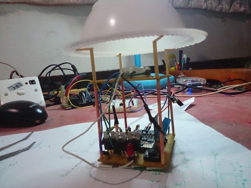
Very nice juan..
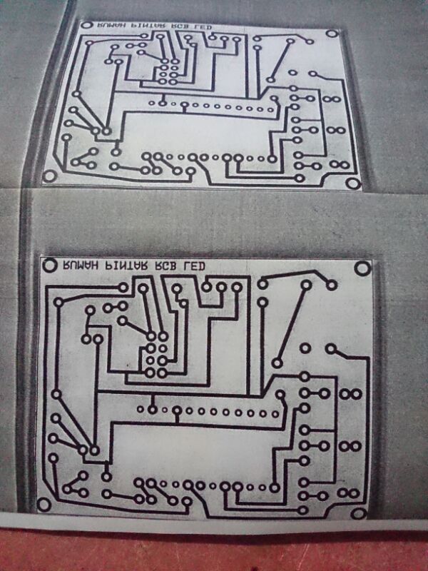
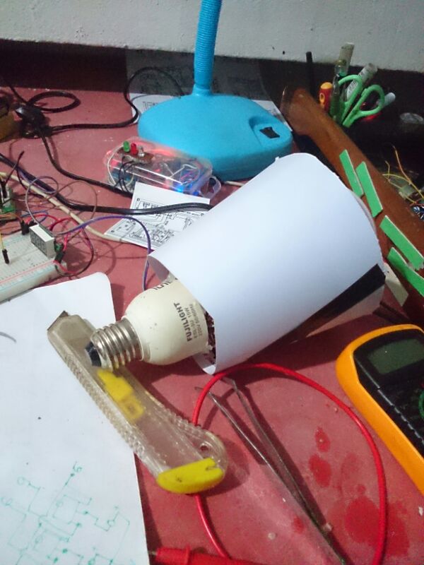
Well, I done two versions of a PCB to put an ESP12 on It and control some devices, and I designed a 3d printed box to host it and install on any place :) Here are some photos:
And the full album:I need to make some final modifications to get more space to connections and the connection to the GPIO15, when changes are done I'll share all the info and a Sketch to compile directly over this PCB. I maded one Sketch right now, but Im gonna do more examples related to this Board, including PIR sensors, and other combinations.Regards.
El lunes, 8 de junio de 2015, 15:36:49 (UTC+2), Juan Pinto escribió:
From Pin3 = A2 on Attiny to RX on ESP :PYou must follow the Pinout from the Wiki as I posted before.You can see on my previous post the SoftwareSerial declaration, this refers to IO pins and not to the fisical pins, you can change the pin on the SoftwareSerial declarationRegards
2015-06-08 9:41 GMT+02:00 Domenico Carvetta <carvetta...@gmail.com>:
Thanks Dario.Most likely I got a bit confusion about pin number vs. datasheet pin assignment.That's mean I assumed before Pin3 and Pin4 of ATtiny related to A2 and GND.Now, after read the SoftwareSerial doc, I understood that Pin3 and Pin4 are respectevely AnalogRead (3) and AnalogRead (2).
--
You received this message because you are subscribed to a topic in the Google Groups "souliss" group.
To unsubscribe from this topic, visit https://groups.google.com/d/topic/souliss/1kMAltPB2ME/unsubscribe.
To unsubscribe from this group and all its topics, send an email to souliss+u...@googlegroups.com.
To post to this group, send email to sou...@googlegroups.com.
To view this discussion on the web visit https://groups.google.com/d/msgid/souliss/bba3da15-ba35-4843-ab04-7ea40ebfe53c%40googlegroups.com.
--
You received this message because you are subscribed to the Google Groups "souliss" group.
To unsubscribe from this group and stop receiving emails from it, send an email to souliss+u...@googlegroups.com.
To post to this group, send email to sou...@googlegroups.com.
To view this discussion on the web visit https://groups.google.com/d/msgid/souliss/6b22ed7b-3dff-459c-b9c7-f5bcf098625c%40googlegroups.com.

Marko S
Dne ponedeljek, 15. junij 2015 18.17.53 UTC+2 je oseba Juan Pinto napisala:
Well, I done two versions of a PCB to put an ESP12 on It and control some devices, and I designed a 3d printed box to host it and install on any place :) Here are some photos:
And the full album:I need to make some final modifications to get more space to connections and the connection to the GPIO15, when changes are done I'll share all the info and a Sketch to compile directly over this PCB. I maded one Sketch right now, but Im gonna do more examples related to this Board, including PIR sensors, and other combinations.Regards.
El lunes, 8 de junio de 2015, 15:36:49 (UTC+2), Juan Pinto escribió:
From Pin3 = A2 on Attiny to RX on ESP :PYou must follow the Pinout from the Wiki as I posted before.You can see on my previous post the SoftwareSerial declaration, this refers to IO pins and not to the fisical pins, you can change the pin on the SoftwareSerial declarationRegards
2015-06-08 9:41 GMT+02:00 Domenico Carvetta <carvetta...@gmail.com>:
Thanks Dario.Most likely I got a bit confusion about pin number vs. datasheet pin assignment.That's mean I assumed before Pin3 and Pin4 of ATtiny related to A2 and GND.Now, after read the SoftwareSerial doc, I understood that Pin3 and Pin4 are respectevely AnalogRead (3) and AnalogRead (2).
--
You received this message because you are subscribed to a topic in the Google Groups "souliss" group.
To unsubscribe from this topic, visit https://groups.google.com/d/topic/souliss/1kMAltPB2ME/unsubscribe.
To unsubscribe from this group and all its topics, send an email to souliss+u...@googlegroups.com.
To post to this group, send email to sou...@googlegroups.com.
Juan Pinto
To view this discussion on the web visit https://groups.google.com/d/msgid/souliss/19cd5f07-116d-4e17-8abe-befbea857f38%40googlegroups.com.
Juan Pinto
To unsubscribe from this group and all its topics, send an email to souliss+unsubscribe@googlegroups.com.
To post to this group, send email to sou...@googlegroups.com.
Juan Pinto
Marko S
Juan Pinto
Nice great news, also thanks for the link.. One design of your pcb is 5x5cm sized right? So chinese pcb makers should be able to cheaply produce it :)
--
You received this message because you are subscribed to a topic in the Google Groups "souliss" group.
To unsubscribe from this topic, visit https://groups.google.com/d/topic/souliss/1kMAltPB2ME/unsubscribe.
To unsubscribe from this group and all its topics, send an email to souliss+u...@googlegroups.com.
To post to this group, send email to sou...@googlegroups.com.
To view this discussion on the web visit https://groups.google.com/d/msgid/souliss/5cfd3e07-8ab6-4b04-993a-a7d5a7ceef19%40googlegroups.com.
Juan Pinto
El miércoles, 24 de junio de 2015, 15:24:44 (UTC+2), Juan Pinto escribió:
Yes, is designed on 5x5cm to make the production easy and cheap :) If I have some time this weekend I'll share the sources.Regards
2015-06-24 12:51 GMT+02:00 Marko S <mark...@gmail.com>:
Nice great news, also thanks for the link.. One design of your pcb is 5x5cm sized right? So chinese pcb makers should be able to cheaply produce it :)
--
You received this message because you are subscribed to a topic in the Google Groups "souliss" group.
To unsubscribe from this topic, visit https://groups.google.com/d/topic/souliss/1kMAltPB2ME/unsubscribe.
To unsubscribe from this group and all its topics, send an email to souliss+unsubscribe@googlegroups.com.
To post to this group, send email to sou...@googlegroups.com.
Di Maio, Dario
Juan Pinto
Di Maio, Dario
Juan Pinto
Juan Pinto
domenico carvetta
Lesjaw Ardi™ ♂
--
You received this message because you are subscribed to the Google Groups "souliss" group.
To unsubscribe from this group and stop receiving emails from it, send an email to souliss+u...@googlegroups.com.
To post to this group, send email to sou...@googlegroups.com.
To view this discussion on the web visit https://groups.google.com/d/msgid/souliss/eb0527ec-c892-4957-bfad-f080d2f66235%40googlegroups.com.
Juan Pinto
--
You received this message because you are subscribed to a topic in the Google Groups "souliss" group.
To unsubscribe from this topic, visit https://groups.google.com/d/topic/souliss/1kMAltPB2ME/unsubscribe.
To unsubscribe from this group and all its topics, send an email to souliss+u...@googlegroups.com.
To post to this group, send email to sou...@googlegroups.com.
To view this discussion on the web visit https://groups.google.com/d/msgid/souliss/CAJ6Uq_%3DC9n8QcBdb47YVS1CHq1mKBuNayUE6WMT_XDXb5LR75g%40mail.gmail.com.
Lesjaw Ardi™ ♂
Lesjaw Ardi™ ♂
This is an onboarding app based on https://github.com/chriscook8/esp-arduino-apboot
The changes relative to that version are as follows:Restructured some of the code to (hopefully) make it a little more understandable
Don't store the ssid and password in EEPROM since the ESP8266 SDK already stores them if wifi_station_set_auto_connect is set to true (this is the default behavior), see
Support ssid and password containing spaces
Restart the node in WIFI_STA mode once the ssid and password have been configured and a successful connection to that AP has been established.
Once restarted advertise the address via mDNS
Domenico Carvetta
Juan Pinto
Di Maio, Dario
Hi Lesjaw,
please open an issue with those information, I will process them at later time.
Thanks,
Dario.
From Mobile.
To view this discussion on the web visit https://groups.google.com/d/msgid/souliss/CAJ6Uq_mezUkzw1rLJBKBZkEZxW-V-NL1sMgG8Ni%3DpqHBcxOY0Q%40mail.gmail.com.
Lesjaw Ardi™ ♂
To view this discussion on the web visit https://groups.google.com/d/msgid/souliss/CAKGhMPJXhAQpVhQ_rHAZSVBJrrCB%3DqT-Jio_bFuVeu0f_eBMBw%40mail.gmail.com.
Juan Pinto
Regards
Lesjaw Ardi™ ♂
To view this discussion on the web visit https://groups.google.com/d/msgid/souliss/cb6db59a-ef9a-49e8-aff4-4773e173819a%40googlegroups.com.
Juan Pinto
Lesjaw Ardi™ ♂
Can you make it as library juan?
Perhaps Dario can integrAte it into NetworkSetup.cpp..
To view this discussion on the web visit https://groups.google.com/d/msgid/souliss/02e5ae71-543e-40b4-8cc5-029899327d1b%40googlegroups.com.
Domenico Carvetta
sketch_jul05b.ino: In function 'void setupWebServerHandlers(int)':
sketch_jul05b.ino:209:12: error: 'class ESP8266WebServer' has no member named 'onNotFound'
sketch_jul05b.ino:213:12: error: 'class ESP8266WebServer' has no member named 'onNotFound'
sketch_jul05b.ino: In function 'void handleNotFound()':
sketch_jul05b.ino:308:21: error: 'class ESP8266WebServer' has no member named 'args'
sketch_jul05b.ino:310:34: error: 'class ESP8266WebServer' has no member named 'args'
sketch_jul05b.ino:311:29: error: 'class ESP8266WebServer' has no member named 'argName'
sketch_jul05b.ino:311:61: error: invalid conversion from 'uint8_t {aka unsigned char}' to 'const char*' [-fpermissive]
In file included from sketch_jul05b.ino:15:0:
C:\Users\Carvetta\Desktop\ESP8266\arduino-1.6.1-esp8266\arduino-1.6.1\hardware\esp8266com\esp8266\libraries\ESP8266WebServer\src/ESP8266WebServer.h:56:9: error:   initializing argument 1 of 'String ESP8266WebServer::arg(const char*)' [-fpermissive]
  String arg(const char* name);
         ^
Lesjaw Ardi™ ♂
--
You received this message because you are subscribed to the Google Groups "souliss" group.
To unsubscribe from this group and stop receiving emails from it, send an email to souliss+u...@googlegroups.com.
To post to this group, send email to sou...@googlegroups.com.
To view this discussion on the web visit https://groups.google.com/d/msgid/souliss/e2880ead-f298-4724-8b10-59e6477b92cf%40googlegroups.com.
Lesjaw Ardi™ ♂
Domenico Carvetta
Lesjaw Ardi™ ♂
Where I missed the bracket? Thanks.
--
You received this message because you are subscribed to the Google Groups "souliss" group.
To unsubscribe from this group and stop receiving emails from it, send an email to souliss+u...@googlegroups.com.
To post to this group, send email to sou...@googlegroups.com.
To view this discussion on the web visit https://groups.google.com/d/msgid/souliss/3e7e7f33-835c-4658-90cf-3fae412f5ac4%40googlegroups.com.

yt1...@gmail.com
...Dallas IntegrationIn most cases OneWire library isn't on the Arduino IDE or have an Older version, be sure to download the ESP one: https://github.com/esp8266/Arduino/tree/esp8266/libraries/OneWire- Example:
#include "bconf/MCU_ESP8266.h" // Load the code directly on the ESP8266
#include "conf/Gateway.h" // The main node is the Gateway, we have just one node
#include "conf/DynamicAddressing.h" // Use dynamic addressing
// Define the WiFi name and password
#define WIFICONF_INSKETCH
#define WiFi_SSID "SSID"
#define WiFi_Password "PASSWORD"
// Include framework code and libraries
#include <ESP8266WiFi.h>
#include <EEPROM.h>
#include "Souliss.h"
// This identify the number of the SLOT logic
#define DALLAS 0
#include <OneWire.h>
#include <DallasTemperature.h>
#define DALLASPIN 4 //Se declara el pin donde se conectará la DATA
OneWire ourWire(DALLASPIN); //Se establece el pin declarado como bus para la comunicación OneWire
DallasTemperature sensors(&ourWire); //Se instancia la librería DallasTemperature
void setup()
{
Initialize();
Serial.begin(115200);
sensors.begin(); //Se inician los sensores DS18B20
// Connect to the WiFi network and get an address from DHCP
Setup_ESP8266();
SetAsGateway(myvNet_esp8266); // Set this node as gateway for SoulissApp
Set_Temperature(DALLAS);
}
void loop()
{
EXECUTEFAST() {
Lesjaw Ardi™ ♂
--
You received this message because you are subscribed to the Google Groups "souliss" group.
To unsubscribe from this group and stop receiving emails from it, send an email to souliss+u...@googlegroups.com.
To post to this group, send email to sou...@googlegroups.com.
To view this discussion on the web visit https://groups.google.com/d/msgid/souliss/26103181-96dc-43b6-82a5-fff5303c9b12%40googlegroups.com.
Domenico Carvetta
Lesjaw Ardi™ ♂
The compile error like you miss a bracket.. but it seems not..
HI Lesjaw,you are lucky..:-) ..btw, you said before I missed any bracket; where ? I wait your appreciated answer,Thanks.
--
You received this message because you are subscribed to the Google Groups "souliss" group.
To unsubscribe from this group and stop receiving emails from it, send an email to souliss+u...@googlegroups.com.
To post to this group, send email to sou...@googlegroups.com.
To view this discussion on the web visit https://groups.google.com/d/msgid/souliss/23df6569-db8a-4cea-a7e7-e0525f7a84a7%40googlegroups.com.
carvetta...@gmail.com
We both use ide 1.6.1.
Thanks.
Inviato da HTC
To unsubscribe from this topic, visit https://groups.google.com/d/topic/souliss/1kMAltPB2ME/unsubscribe.
To unsubscribe from this group and all its topics, send an email to souliss+u...@googlegroups.com. To view this discussion on the web visit https://groups.google.com/d/msgid/souliss/CAJ6Uq_kg-dR3AZW7L5EiP%3DvHcWb3nP8DVM%2BEfVupQzRWVrd%2BfQ%40mail.gmail.com.
Juan Pinto
To view this discussion on the web visit https://groups.google.com/d/msgid/souliss/559bc383.2a0bc30a.f7b8.ffffb49a%40mx.google.com.
carvetta...@gmail.com
Lesjaw Ardi™ ♂
Sorry by the double post, I renamed the example and the link from the previous message isn't work, here is the new one:
https://github.com/juanpintom/Souliss_ESP_Examples/blob/master/E00_ESP_Helloworld_WiFiManager
Regards
To view this discussion on the web visit https://groups.google.com/d/msgid/souliss/CAKGhMPJXhAQpVhQ_rHAZSVBJrrCB%3DqT-Jio_bFuVeu0f_eBMBw%40mail.gmail.com.
Juan Pinto
Ok, Ty for the update :) I can't do tests with 01 and 03
You received this message because you are subscribed to a topic in the Google Groups "souliss" group.
To unsubscribe from this topic, visit https://groups.google.com/d/topic/souliss/1kMAltPB2ME/unsubscribe.
To unsubscribe from this group and all its topics, send an email to souliss+u...@googlegroups.com.
To post to this group, send email to sou...@googlegroups.com.
To view this discussion on the web visit https://groups.google.com/d/msgid/souliss/CAJ6Uq_m9oE-MLVKTUW4aVhjWLbKyr7XF8HfftCSuKfzq7rPhHg%40mail.gmail.com.
Lesjaw Ardi™ ♂
To view this discussion on the web visit https://groups.google.com/d/msgid/souliss/CAN5yH6FOGOY8C1dM6zcE9fMNZqtZBn_TiYgOMHrus6X%2BXMMnKw%40mail.gmail.com.
Lesjaw Ardi™ ♂
Lesjaw Ardi™ ♂
Lesjaw Ardi™ ♂
Lesjaw Ardi™ ♂
void setup()
{
Serial.begin(115200);
wifi.autoConnect("Souliss");
WiFi.mode(WIFI_STA);
Initialize();
// Set network parameters
Souliss_GetIPAddress();
SetAsGateway(myvNet_dhcp);
SetAddressingServer();
void setup(){
Serial.begin(115200);
wifi.autoConnect("Souliss");
WiFi.mode(WIFI_STA);
Initialize();
// This board request an address to the gateway at runtime, no need
// to configure any parameter here.
GetIPAddress();
SetDynamicAddressing();
GetAddress();
void setup(){
Serial.begin(115200);
wifi.autoConnect("Souliss");
WiFi.mode(WIFI_STA);
Initialize();
GetIPAddress();
SetAddress(0xAB02, 0xFF00, 0xAB01);
Lesjaw Ardi™ ♂
Di Maio, Dario
Hi,
Looks that EEPROM library isn't commiting data.
If the address is not retained while the power has been removed, the node will ask for a new address, that's why you see two nodes.
The healthy value is updates slowly and may take a while before detecting a mussing node.
Dario.
From Mobile.
Di Maio, Dario
You can mix static and dynamic addressing, the peer will just not request for an address but will broadcast its one to the gateway.
Remove power from the gateway and peer, restart only the gateway and rebuild your DB, so that you can see if addresses has been retained.
Dario.
From Mobile.
Lesjaw Ardi™ ♂
--
You received this message because you are subscribed to the Google Groups "souliss" group.
To unsubscribe from this group and stop receiving emails from it, send an email to souliss+u...@googlegroups.com.
To post to this group, send email to sou...@googlegroups.com.
To view this discussion on the web visit https://groups.google.com/d/msgid/souliss/CAKGhMPKSWrJPvo6%2BwaaXBBDqmAN6DBBPTK4eMT8C%3D%2BAAMSxuhQ%40mail.gmail.com.