AWP07L Wifi Socket

Ciaran Baulig

Philip Knowles
If you can upload a pic someone may be able to work it out for you.
Regards
Phil K
Sent from Mail for Windows 10
From: Ciaran Baulig
Sent: 17 August 2018 16:57
To: SonoffUsers
Subject: AWP07L Wifi Socket
Hey,
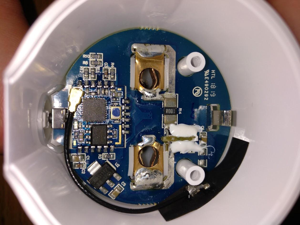
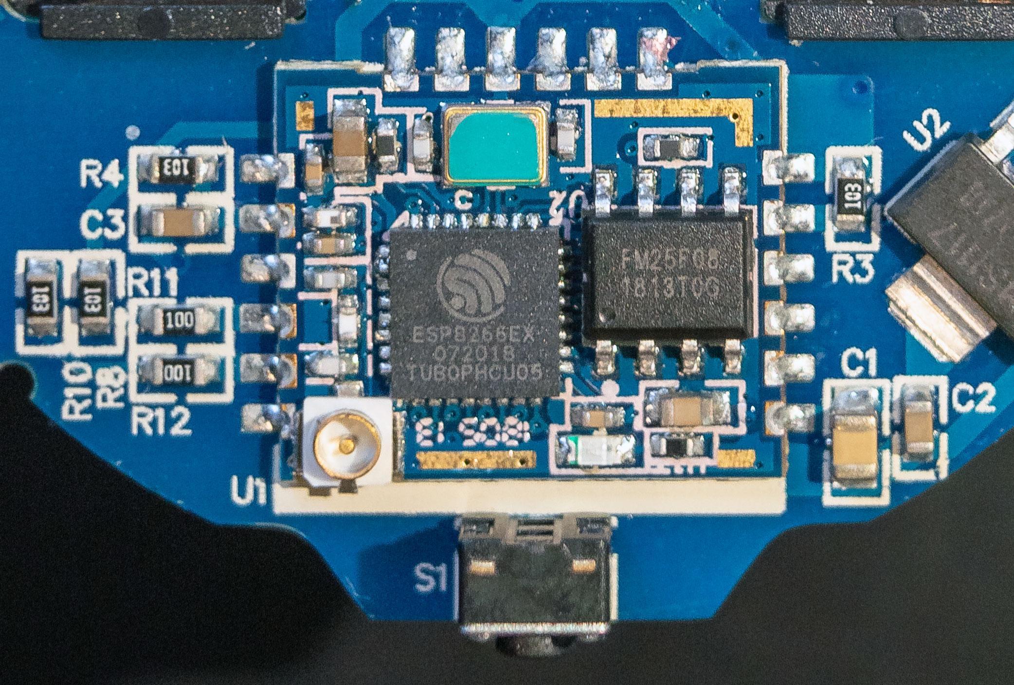
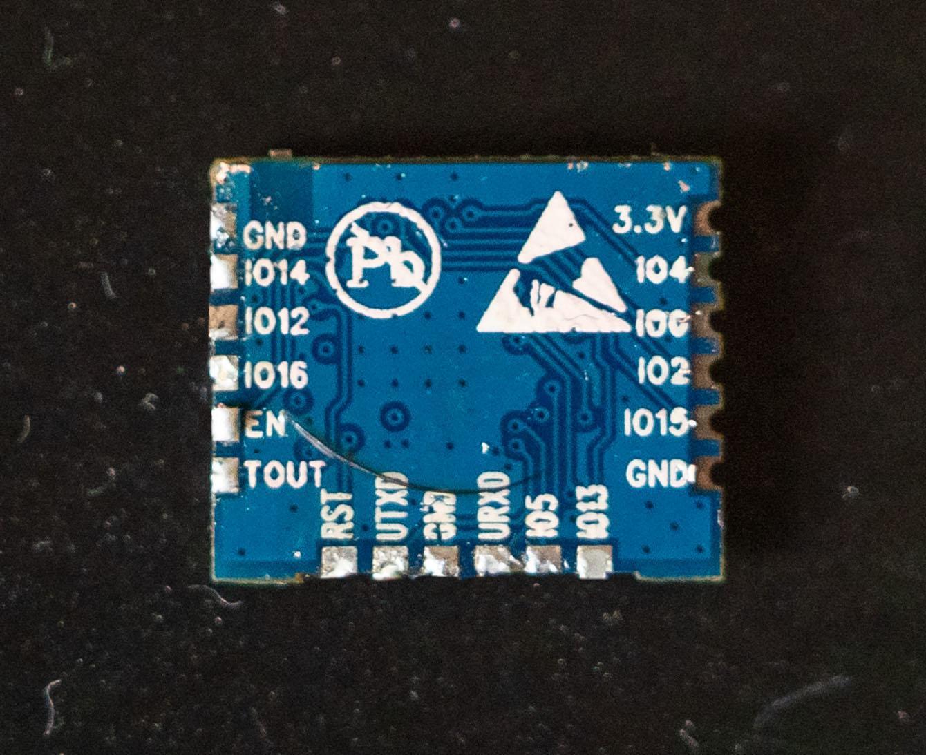
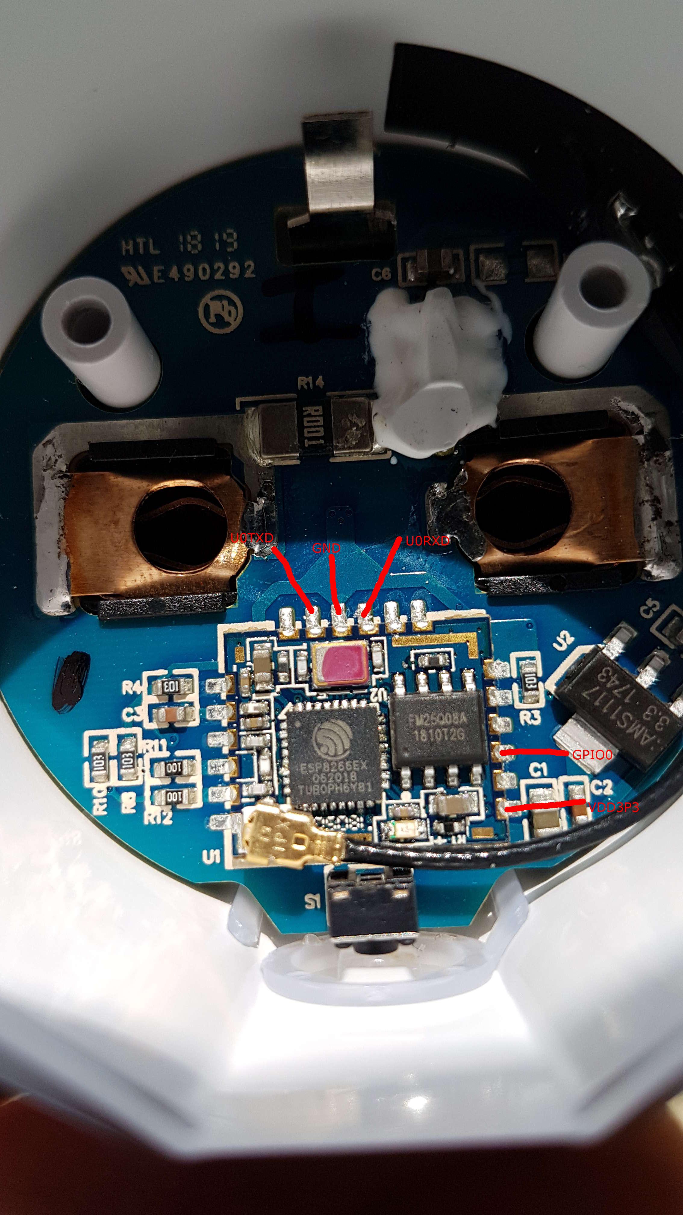
I recently bought a new smart socket that uses an ESP8266EX. Unfortunately I don't know which pins I should solder to to upload Tasmota (no labeling on the PCB). Can anyone help me out here?
Thanks in advance.
ciB
![]()
--
You received this message because you are subscribed to the Google Groups "SonoffUsers" group.
To unsubscribe from this group and stop receiving emails from it, send an email to sonoffusers...@googlegroups.com.
For more options, visit https://groups.google.com/d/optout.
Ciaran Baulig

Phil

David
Am Freitag, 17. August 2018 17:57:03 UTC+2 schrieb Ciaran Baulig:
Hey,I recently bought a new smart socket that uses an ESP8266EX. Unfortunately I don't know which pins I should solder to to upload Tasmota (no labeling on the PCB). Can anyone help me out here?Thanks in advance.ciB

David Windhausen

Thomas Froitzheim

Sandro Sandro
Houzetek AWP07L

Hauke Walden
thanky you very much, this was most helpful!
One question remains: If I use setCurrent(0.164), setVoltage(231) and setPower(40W), I do get the values as expected. However, If I then replace the 40W light bulb with a 12,5W, I get the correct Wattage (13), but the same current(0.164) as before and therefore of course a wrong voltage (82V). Shouldn't it be enough to set just 2 of the values?! I don't understand how the calibration mechanism works - maybe you can shed some even more light?
Thank you!
Sandro Sandro
Hauke Walden
see Davids two posts (https://groups.google.com/d/msg/sonoffusers/v0hEUKN5hpQ/MN5h_yAwAwAJ).
For the time being, you *must* change the source code in sonoff_template.h.
Here's what I have done:
1. Change the enum SupportedModules
3. Add this to the enum at the end of the file:
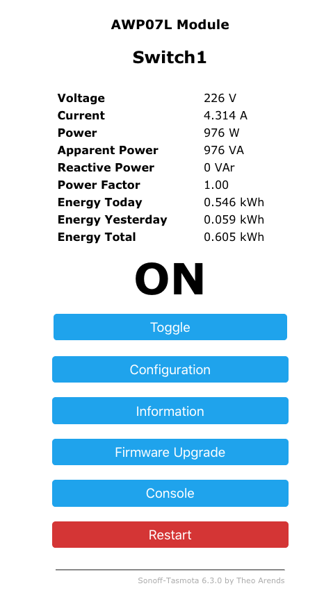
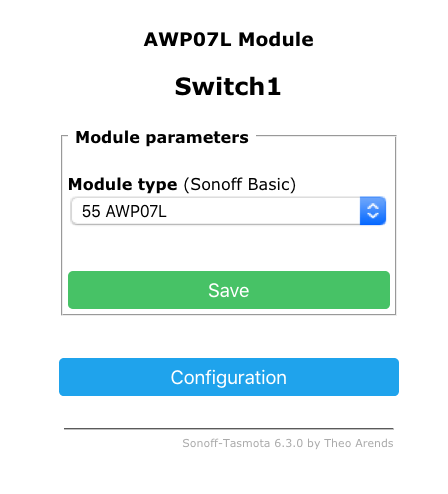
Build a minimum image, flash it, build a standard image, flash it, and select "AWP07L" from the device list. Afterwards, don't forget to calibrate (as David has described above).
Good luck!
Hauke Walden
are either wrong or have changed since 6.1.
They are replaced by
Sandro Sandro

Gianluca Perez
I'd tried to follow your instructions but now i've a plug that has a blue led always on and that is alway active. The fisic button do not shut off the plug and the plug do not connect via wifi.
Can anyone help me please?
I'd used atom and platformio to flash, used the last Tasmota release, changed the sonoff_template.h as Hauke said, then flash first minimal then standard image

wolly Domotica
Phil
wolly Domotica
Phil
Philip Knowles
There’s a problem with this though. This table shows the results for differing voltages
V | I | R | W |
250 | 0.260417 | 960 | 65.10417 |
245 | 0.255208 | 960 | 62.52604 |
240 | 0.25 | 960 | 60 |
235 | 0.244792 | 960 | 57.52604 |
230 | 0.239583 | 960 | 55.10417 |
225 | 0.234375 | 960 | 52.73438 |
220 | 0.229167 | 960 | 50.41667 |
The only constant is the resistance so at 235V your 60W bulb is only using 57.5V of Power.
What you should really do to calibrate is to measure the resistance of the bulb and then measure the Voltage. You can then use Ohm’s Law to calculate the Current. If you put those 2 values in you should have a true calibration. To be really accurate you should measure the resistance of the bulb when it’s hot.
--

Colin Law
Phil
wolly Domotica
Il giorno martedì 26 marzo 2019 19:03:15 UTC+1, Phil ha scritto:
I dont think you need to! google led me here http://www.avatarcontrols.com/index.php?ac=article&at=read&did=191 and scrolling down the page revels the free
Phil
FLASH third-party firmware
BE SURE THE FIRMWARE FITS YOUR DEVICE!
Place or link your binary file to ./files/thirdparty.bin.
Currently a Sonoff-Tasmota v6.5.0 basic build is already included. It will open an WiFi access point named sonoff-XXX. Please note that while we include this for your convenience, we are not affliated with the Sonoff-Tasmota project and cannot provide support for post installation issues. Please refer to the respective project for support.
Binary requirements:
- full binary including first-stage bootloader
- maximum filesize 512KB for first flash
Start flashing process
# curl http://10.42.42.42/flash3
Alternatively you can request a certain file to be requested and flashed by the device:
# curl http://10.42.42.42/flash3?url=http://10.42.42.1/files/thirdparty.bin
from https://github.com/ct-Open-Source/tuya-convert

paukl

Anders Frihagen

AF-J

Utz Späth
AF-J
El viernes, 17 de agosto de 2018, 17:57:03 (UTC+2), Ciaran Baulig escribió:
