TMS9918 video card

J.B. Langston

David Lee
David Lee

Thomas Jager

TonyD
http://www.classiccmp.org/cini/pdf/byte/Hi-Res%20Graphics%20TMS9918%20BYTE%200882.pdf.pdf
- Tony

Spencer Owen
After I finish my AVR BootIO device my next project is going to be a TMS9918-based video card. I got bored with working on the BootIO card for a while so I took a break to lay out the PCB for this. The kicad files are here: https://github.com/jblang/rc9918. I've attached PDF schematics and images of the PCB layout and 3D render from KiCad. Disclaimer: this is completely untested; hasn't even been breadboarded yet. I need to make a Mouser order for several of the components before I can do that.I followed the circuit design for interfacing the TMS9918 with SRAM in this doc: https://retrobrewcomputers.org/n8vem-pbwiki-archive/0/35845334/48860720/33053543/SRAM%20Replacement%20for%20TMS99x8%20VRAM.pdf.
--
You received this message because you are subscribed to the Google Groups "RC2014-Z80" group.
To unsubscribe from this group and stop receiving emails from it, send an email to rc2014-z80+unsubscribe@googlegroups.com.
To post to this group, send email to rc201...@googlegroups.com.
To view this discussion on the web, visit https://groups.google.com/d/msgid/rc2014-z80/5bcdeaac-a81e-40d9-8a38-8d05810e71bc%40googlegroups.com.
For more options, visit https://groups.google.com/d/optout.
J.B. Langston

Jac Goudsmit
To view this discussion on the web, visit https://groups.google.com/d/msgid/rc2014-z80/873d7bdd-fe45-4430-bf16-6a42c162d243%40googlegroups.com.
J.B. Langston
J.B. Langston

Wayne Warthen
That looks great! Looking forward to seeing it in action.How do you plan to drive it? The main thing that has held me back from making a video card is the software side of things. I can imagine that updating either BASIC or CP/M to address this card would be quite an undertaking - at least for me it would be! I'm sure it's going to work great though :)
J.B. Langston
Wayne Warthen
--
You received this message because you are subscribed to the Google Groups "RC2014-Z80" group.
To unsubscribe from this group and stop receiving emails from it, send an email to rc2014-z80+unsubscribe@googlegroups.com.
To post to this group, send email to rc201...@googlegroups.com.
To view this discussion on the web, visit https://groups.google.com/d/msgid/rc2014-z80/720b7c5c-c893-42e4-9a27-37e6b0a297e1%40googlegroups.com.
J.B. Langston
On Monday, February 5, 2018 at 7:18:06 PM UTC-6, J.B. Langston wrote:

Ed Brindley

Mike Strange
<SNIP>
Ed Brindley
J.B. Langston
J.B. Langston
J.B. Langston
Ed Brindley
J.B. Langston
J.B. Langston
Mike Strange
You received this message because you are subscribed to a topic in the Google Groups "RC2014-Z80" group.
To unsubscribe from this topic, visit https://groups.google.com/d/topic/rc2014-z80/0m0kbzIJ3tw/unsubscribe .
To unsubscribe from this group and all its topics, send an email to rc2014-z80+...@googlegroups.com.
To post to this group, send email to
To view this discussion on the web, visit https://groups.google.com/d/msgid/rc2014-z80/bbf9a70a-8b4d-47e7-bc59-1f13b0a936e5%40googlegroups.com .
For more options, visit https://groups.google.com/d/optout.
|
|
Virus-free.
www.avg.com
|
J.B. Langston
On Wednesday, February 7, 2018 at 11:25:26 AM UTC-6, Mike Strange wrote:
The reason for the bypass capacitors at one per device is to filter out the transient spikes of current caused by fast rise and fall times; these became very much worse with 74S devices.
This was just one of the reasons for multi-layer boards with 0V and 5V ground-planes; a swine to de-solder components from but brilliant at minimising inductance.
Mike
Date sent: Wed, 7 Feb 2018 07:39:09 -0800 (PST)From: "J.B. Langston" <jb.la...@gmail.com>To: RC2014-Z80 <rc201...@googlegroups.com>Subject: [rc2014-z80] Re: TMS9918 video card
Send reply to: rc2014-z80@googlegroups.com
You got me thinking about this and I guess I should explain why I placed the caps where I did. I've seen people stating you should place the bypass cap as close to the VCC pin as possible but since electrons flow opposite to conventional current that doesn't seem right I guess what you're actually bypassing is the AC caused by power draw so really the current would be flowing in both directions. Ideally I would think the cap should be as close to both pins as possible but the placement of VCC and GND on opposite corners of most logic chips makes that impossible. I've never understood why they did that. My understanding is what you're trying to minimize is inductance in the wires, but I'm not sure if having one lead shorter than the other would be preferable to having them both be an equal length from both pins. It should still be roughly the same length of wire in total. In any case there are the bond wires inside the package to consider too, which have to come from opposite corners to the center, so stressing over the exact placement of the cap too much is probably futile. I guess I should just go with conventional wisdom and put it near VCC so I don't confuse people.
On Wednesday, February 7, 2018 at 9:13:34 AM UTC-6, J.B. Langston wrote:Sorry, I got the references backward. C5 is for U5 and C9 is for U4. But the point still remains that both caps are right next to the respective chips and connected directly across their VCC and GND, as close to half way between the terminals as I could get.
On Wednesday, February 7, 2018 at 9:11:38 AM UTC-6, J.B. Langston wrote:Thanks!
I'm not sure what you mean about the bypass cap. C9 is right next to U5 and connected across it's VCC and GND pins. C5 is the bypass cap for U4. The bypass cap for each of the '574s is in the upper left corner of the respective chip, with traces going to VCC and GND on the respective chip.
For the TMS9918s, I just ordered two off of eBay--they cost me about $10 each including shipping. There were some in China for considerably cheaper but I was wary of those after reading about fake chips from China so I opted to pay a bit more for the ones I found in the US. I haven't tested them yet--hopefully they work.
On the HM62256BLP-7, the chip I actually plan to use is the UM61M256K-15. I've got 8 of them that I pulled off of an old Pentium motherboard. These are narrow DIP-28s but KiCad doesn't have them in its library. I was being lazy and picked the other model after verifying that the pinout was the same. It didn't occur to me that the footprint might be different. I will change the model number on the chip. Mike, I'm sorry you ordered based on incorrect information. I guess it should be possible to modify the layout to accomodate the other chip. U2 could be rotated and moved to the left side and all of the 574s could be nudged down.
On Wednesday, February 7, 2018 at 5:04:47 AM UTC-6, Ed Brindley wrote:Hi JB,
Nice work, design looks good :)
Very nit-picky comment - C9 should be near U5 rather than U4, and U4 doesn't appear to have a bypass cap?
Have you got a source for TMS9918s? I see there are a few on eBay but that's all I've found so far.
Cheers,Ed
On Wednesday, 7 February 2018 02:41:25 UTC, J.B. Langston wrote:I've updated the PCB layout to put the video connector on the other end. I also added copper pours and significantly reduced the via count. The changes have been pushed to github and images are attached.
On Monday, February 5, 2018 at 7:18:06 PM UTC-6, J.B. Langston wrote:After I finish my AVR BootIO device my next project is going to be a TMS9918-based video card. I got bored with working on the BootIO card for a while so I took a break to lay out the PCB for this. The kicad files are here: https://github.com/jblang/rc9918. I've attached PDF schematics and images of the PCB layout and 3D render from KiCad. Disclaimer: this is completely untested; hasn't even been breadboarded yet. I need to make a Mouser order for several of the components before I can do that.
I followed the circuit design for interfacing the TMS9918 with SRAM in this doc: https://retrobrewcomputers.org/n8vem-pbwiki-archive/0/35845334/48860720/33053543/SRAM%20Replacement%20for%20TMS99x8%20VRAM.pdf .
--
You received this message because you are subscribed to a topic in the Google Groups "RC2014-Z80" group.
To unsubscribe from this topic, visit https://groups.google.com/d/topic/rc2014-z80/0m0kbzIJ3tw/unsubscribe
.
To unsubscribe from this group and all its topics, send an email to rc2014-z80+unsubscribe@googlegroups.com.
To post to this group, send email to
To view this discussion on the web, visit
https://groups.google.com/d/msgid/rc2014-z80/bbf9a70a-8b4d-47e7-bc59-1f13b0a936e5%40googlegroups.com .
For more options, visit https://groups.google.com/d/optout.
mjstrange
Ed Brindley
I rearranged the ICs as a quick test and just about got it to fit - it's a tight squeeze though - see attached pic. Thinking some things are too close, especially if one was to use IC sockets.
I used Freerouter (heresy I know) so excuse any weird trace angles etc :D I will have another go and route it properly if it works on breadboard.
Another thing I thought of, ideally the M1 line should be included in the address decoding, otherwise strange things may happen when you start using interrupts. If you search this group there are some posts from (I think) Ben Chong and PianoMatt talking about it.
Cheers,
Ed
Jac Goudsmit
--
You received this message because you are subscribed to the Google Groups "RC2014-Z80" group.
To unsubscribe from this group and stop receiving emails from it, send an email to rc2014-z80+unsubscribe@googlegroups.com.
To post to this group, send email to rc201...@googlegroups.com.
To view this discussion on the web, visit https://groups.google.com/d/msgid/rc2014-z80/71445378-07a6-400c-bb96-6114a135b123%40googlegroups.com.
J.B. Langston
J.B. Langston

Steve Cousins
J.B. Langston
Steve Cousins
J.B. Langston

A A
On Tuesday, February 6, 2018 at 10:59:43 AM UTC-7, Wayne Warthen wrote:
RomWBW has substantial support for the TMS9918. If a system is able to run RomWBW (has a Scott Baker 512KB RAM/ROM module), it is probably trivial to configure RomWBW to this new module (mostly I/O port changes). Otherwise, the code in RomWBW could potentially be a base for new code in the standard RC2014 CP/M (I assume).
Outside of cpm there is also support in z88dk from C. It's mainly aimed at the 9918 variant in the sega master system but it shows what is possible. This is a game written in C using the devkitSMS 9918+ library incorporated into the compiler:
https://www.youtube.com/watch?v=fl1NyV_Ui7o
In addition to this there are standard text terminals stdin,stdout,stderr already implemented (although the sms has no common keyboard so stdin is omitted).
Ed Brindley
Ed Brindley
J.B. Langston
J.B. Langston
Ed Brindley
J.B. Langston

Mark T
J.B. Langston

Jay Cotton
On Sunday, June 10, 2018 at 1:46:55 PM UTC-7, J.B. Langston wrote:
Got it fully working now...
J.B. Langston

Olaf Dannath

Randy Mongenel
--
You received this message because you are subscribed to the Google Groups "RC2014-Z80" group.
To unsubscribe from this group and stop receiving emails from it, send an email to rc2014-z80+unsubscribe@googlegroups.com.
To post to this group, send email to rc201...@googlegroups.com.
To view this discussion on the web, visit https://groups.google.com/d/msgid/rc2014-z80/530929ff-65c3-462e-ac20-8fe05a17eac5%40googlegroups.com.
J.B. Langston
J.B. Langston
J.B. Langston
J.B. Langston
J.B. Langston
Randy Mongenel
I've got the TMS9918+z80ctrl running an unmodified MSX demo: https://www.youtube.com/watch?v=CIIRPGlvCoU
--
You received this message because you are subscribed to the Google Groups "RC2014-Z80" group.
To unsubscribe from this group and stop receiving emails from it, send an email to rc2014-z80+unsubscribe@googlegroups.com.
To post to this group, send email to rc201...@googlegroups.com.
To view this discussion on the web, visit https://groups.google.com/d/msgid/rc2014-z80/2028b8f4-4668-4e64-8811-4295cc492775%40googlegroups.com.

Scott Lawrence
That's really awesome!Long live the Z80 demoscene :)
On Tue, Jun 19, 2018 at 7:03 AM, J.B. Langston <jb.la...@gmail.com> wrote:
I've got the TMS9918+z80ctrl running an unmodified MSX demo: https://www.youtube.com/watch?v=CIIRPGlvCoU
--
You received this message because you are subscribed to the Google Groups "RC2014-Z80" group.
To unsubscribe from this group and stop receiving emails from it, send an email to rc2014-z80+...@googlegroups.com.
To post to this group, send email to rc201...@googlegroups.com.
To view this discussion on the web, visit https://groups.google.com/d/msgid/rc2014-z80/2028b8f4-4668-4e64-8811-4295cc492775%40googlegroups.com.
--
You received this message because you are subscribed to the Google Groups "RC2014-Z80" group.
To unsubscribe from this group and stop receiving emails from it, send an email to rc2014-z80+...@googlegroups.com.
To post to this group, send email to rc201...@googlegroups.com.
To view this discussion on the web, visit https://groups.google.com/d/msgid/rc2014-z80/CAB4PTAL3vjFXAbyMoM8eSOttxyV9GxV5Fve4Q%3Du%3DGzMOp5WqgA%40mail.gmail.com.
For more options, visit https://groups.google.com/d/optout.
yor...@gmail.com
J.B. Langston
You received this message because you are subscribed to a topic in the Google Groups "RC2014-Z80" group.
To unsubscribe from this topic, visit https://groups.google.com/d/topic/rc2014-z80/0m0kbzIJ3tw/unsubscribe.
To unsubscribe from this group and all its topics, send an email to rc2014-z80+...@googlegroups.com.
To post to this group, send email to rc201...@googlegroups.com.
To view this discussion on the web, visit https://groups.google.com/d/msgid/rc2014-z80/CAKD5ztZ1y77TrjPhrjaFeRkOHyKWRU55bxMGAsyArLxyYKqJvg%40mail.gmail.com.
Scott Lawrence
To view this discussion on the web, visit https://groups.google.com/d/msgid/rc2014-z80/CAMwROAyyEfGQdWfBzgPARNNg1KfkEmSYCzhdfTbmP1A8dGf8zA%40mail.gmail.com.
J.B. Langston

Eric Matecki

Mariano Cividino
I'm also interested.
Thanks.
--
You received this message because you are subscribed to the Google Groups "RC2014-Z80" group.
To unsubscribe from this group and stop receiving emails from it, send an email to rc2014-z80+...@googlegroups.com.
To post to this group, send email to rc201...@googlegroups.com.
To view this discussion on the web, visit https://groups.google.com/d/msgid/rc2014-z80/6f5510d7-bc4b-415e-aabc-7dca359faa1f%40googlegroups.com.

Colin Little
J.B. Langston
Olaf Dannath
J.B. Langston
--
You received this message because you are subscribed to a topic in the Google Groups "RC2014-Z80" group.
To unsubscribe from this topic, visit https://groups.google.com/d/topic/rc2014-z80/0m0kbzIJ3tw/unsubscribe.
To unsubscribe from this group and all its topics, send an email to rc2014-z80+...@googlegroups.com.
To post to this group, send email to rc201...@googlegroups.com.
To view this discussion on the web, visit https://groups.google.com/d/msgid/rc2014-z80/7e020466-f78f-447c-8bab-cf06d9373743%40googlegroups.com.
J.B. Langston
Spencer Owen
You received this message because you are subscribed to the Google Groups "RC2014-Z80" group.
To unsubscribe from this group and stop receiving emails from it, send an email to rc2014-z80+...@googlegroups.com.
To post to this group, send email to rc201...@googlegroups.com.
To view this discussion on the web, visit https://groups.google.com/d/msgid/rc2014-z80/CAMwROAxTM%2BqvqkictQ1b3z7KMG%3DSrp7tRjB0aqTzVGz7y56z2w%40mail.gmail.com.
Colin Little
To unsubscribe from this group and all its topics, send an email to rc2014-z80+unsubscribe@googlegroups.com.
J.B. Langston

Michael Kamprath
J.B. Langston
If anyone is interested, I had a number of this board's parts on stock (like the TMS9918A from my TI 99/4a activities), so I can put together kits when the boards come in. I'll sell at cost. Contact me to reserve.
Michael Kamprath
On Sunday, June 24, 2018 at 6:28:59 PM UTC-7, J.B. Langston wrote:
If anyone is interested, I had a number of this board's parts on stock (like the TMS9918A from my TI 99/4a activities), so I can put together kits when the boards come in. I'll sell at cost. Contact me to reserve.Thanks for doing this. I'm sure it is a valuable service to people who don't want to source the parts themselves, and it's really not something I'm interested in doing myself.
Mariano Cividino
Hi,
If you share the desiggn in OSH Park, that is fine for me. I can order from there.
Thanks for your work.
--
You received this message because you are subscribed to the Google Groups "RC2014-Z80" group.
To unsubscribe from this group and stop receiving emails from it, send an email to rc2014-z80+...@googlegroups.com.
To post to this group, send email to rc201...@googlegroups.com.
To view this discussion on the web, visit https://groups.google.com/d/msgid/rc2014-z80/6b75a596-182b-4f9c-948c-40b8d5d40cc4%40googlegroups.com.
J.B. Langston
You received this message because you are subscribed to a topic in the Google Groups "RC2014-Z80" group.
To unsubscribe from this topic, visit https://groups.google.com/d/topic/rc2014-z80/0m0kbzIJ3tw/unsubscribe.
To unsubscribe from this group and all its topics, send an email to rc2014-z80+...@googlegroups.com.
To post to this group, send email to rc201...@googlegroups.com.
To view this discussion on the web, visit https://groups.google.com/d/msgid/rc2014-z80/c4634d93-c9cb-b2d9-8bb1-59127e614b42%40gmail.com.
mjstrange
J.B. Langston
To view this discussion on the web, visit https://groups.google.com/d/msgid/rc2014-z80/5b323f08.1c69fb81.4a6fb.655dSMTPIN_ADDED_BROKEN%40gmr-mx.google.com.
Mariano Cividino
Thanls Sir
To view this discussion on the web, visit https://groups.google.com/d/msgid/rc2014-z80/CAMwROAzBi5NRQcKpeGmuAHMmSajzvsaOfMT6AadKJaEQZ4kY8A%40mail.gmail.com.

Mike Strange
To unsubscribe from this group and stop receiving emails from it, send an email to rc2014-z80+unsubscribe@googlegroups.com.
To post to this group, send email to rc201...@googlegroups.com.
To view this discussion on the web, visit https://groups.google.com/d/msgid/rc2014-z80/6b75a596-182b-4f9c-948c-40b8d5d40cc4%40googlegroups.com.
For more options, visit https://groups.google.com/d/optout.
--
You received this message because you are subscribed to a topic in the Google Groups "RC2014-Z80" group.
To unsubscribe from this topic, visit https://groups.google.com/d/topic/rc2014-z80/0m0kbzIJ3tw/unsubscribe.
To unsubscribe from this group and all its topics, send an email to rc2014-z80+unsubscribe@googlegroups.com.
To post to this group, send email to rc201...@googlegroups.com.
To view this discussion on the web, visit https://groups.google.com/d/msgid/rc2014-z80/c4634d93-c9cb-b2d9-8bb1-59127e614b42%40gmail.com.
For more options, visit https://groups.google.com/d/optout.
--
You received this message because you are subscribed to a topic in the Google Groups "RC2014-Z80" group.
To unsubscribe from this topic, visit https://groups.google.com/d/topic/rc2014-z80/0m0kbzIJ3tw/unsubscribe.
To unsubscribe from this group and all its topics, send an email to rc2014-z80+unsubscribe@googlegroups.com.
To post to this group, send email to rc201...@googlegroups.com.
To view this discussion on the web, visit https://groups.google.com/d/msgid/rc2014-z80/CAMwROAzBi5NRQcKpeGmuAHMmSajzvsaOfMT6AadKJaEQZ4kY8A%40mail.gmail.com.
For more options, visit https://groups.google.com/d/optout.
--
You received this message because you are subscribed to a topic in the Google Groups "RC2014-Z80" group.
To unsubscribe from this topic, visit https://groups.google.com/d/topic/rc2014-z80/0m0kbzIJ3tw/unsubscribe.
To unsubscribe from this group and all its topics, send an email to rc2014-z80+unsubscribe@googlegroups.com.
J.B. Langston
To unsubscribe from this group and stop receiving emails from it, send an email to rc2014-z80+...@googlegroups.com.
To post to this group, send email to rc201...@googlegroups.com.
To view this discussion on the web, visit https://groups.google.com/d/msgid/rc2014-z80/6b75a596-182b-4f9c-948c-40b8d5d40cc4%40googlegroups.com.
For more options, visit https://groups.google.com/d/optout.
--
You received this message because you are subscribed to a topic in the Google Groups "RC2014-Z80" group.
To unsubscribe from this topic, visit https://groups.google.com/d/topic/rc2014-z80/0m0kbzIJ3tw/unsubscribe.
To unsubscribe from this group and all its topics, send an email to rc2014-z80+...@googlegroups.com.
To post to this group, send email to rc201...@googlegroups.com.
To view this discussion on the web, visit https://groups.google.com/d/msgid/rc2014-z80/c4634d93-c9cb-b2d9-8bb1-59127e614b42%40gmail.com.
For more options, visit https://groups.google.com/d/optout.
--
You received this message because you are subscribed to a topic in the Google Groups "RC2014-Z80" group.
To unsubscribe from this topic, visit https://groups.google.com/d/topic/rc2014-z80/0m0kbzIJ3tw/unsubscribe.
To unsubscribe from this group and all its topics, send an email to rc2014-z80+...@googlegroups.com.
To post to this group, send email to rc201...@googlegroups.com.
To view this discussion on the web, visit https://groups.google.com/d/msgid/rc2014-z80/CAMwROAzBi5NRQcKpeGmuAHMmSajzvsaOfMT6AadKJaEQZ4kY8A%40mail.gmail.com.
For more options, visit https://groups.google.com/d/optout.
--
You received this message because you are subscribed to a topic in the Google Groups "RC2014-Z80" group.
To unsubscribe from this topic, visit https://groups.google.com/d/topic/rc2014-z80/0m0kbzIJ3tw/unsubscribe.
To unsubscribe from this group and all its topics, send an email to rc2014-z80+...@googlegroups.com.
To post to this group, send email to rc201...@googlegroups.com.
To view this discussion on the web, visit https://groups.google.com/d/msgid/rc2014-z80/5b323f08.1c69fb81.4a6fb.655dSMTPIN_ADDED_BROKEN%40gmr-mx.google.com.
For more options, visit https://groups.google.com/d/optout.
--
You received this message because you are subscribed to a topic in the Google Groups "RC2014-Z80" group.
To unsubscribe from this topic, visit https://groups.google.com/d/topic/rc2014-z80/0m0kbzIJ3tw/unsubscribe.
To unsubscribe from this group and all its topics, send an email to rc2014-z80+...@googlegroups.com.
To post to this group, send email to rc201...@googlegroups.com.
To view this discussion on the web, visit https://groups.google.com/d/msgid/rc2014-z80/d97802c4-e460-4d1b-b4c0-3fba47152d1e%40googlegroups.com.
Mike Strange
To unsubscribe from this group and stop receiving emails from it, send an email to rc2014-z80+unsubscribe@googlegroups.com.
To post to this group, send email to rc201...@googlegroups.com.
To view this discussion on the web, visit https://groups.google.com/d/msgid/rc2014-z80/6b75a596-182b-4f9c-948c-40b8d5d40cc4%40googlegroups.com.
For more options, visit https://groups.google.com/d/optout.
--
You received this message because you are subscribed to a topic in the Google Groups "RC2014-Z80" group.
To unsubscribe from this topic, visit https://groups.google.com/d/topic/rc2014-z80/0m0kbzIJ3tw/unsubscribe.
To unsubscribe from this group and all its topics, send an email to rc2014-z80+unsubscribe@googlegroups.com.
To post to this group, send email to rc201...@googlegroups.com.
To view this discussion on the web, visit https://groups.google.com/d/msgid/rc2014-z80/c4634d93-c9cb-b2d9-8bb1-59127e614b42%40gmail.com.
For more options, visit https://groups.google.com/d/optout.
--
You received this message because you are subscribed to a topic in the Google Groups "RC2014-Z80" group.
To unsubscribe from this topic, visit https://groups.google.com/d/topic/rc2014-z80/0m0kbzIJ3tw/unsubscribe.
To unsubscribe from this group and all its topics, send an email to rc2014-z80+unsubscribe@googlegroups.com.
To post to this group, send email to rc201...@googlegroups.com.
To view this discussion on the web, visit https://groups.google.com/d/msgid/rc2014-z80/CAMwROAzBi5NRQcKpeGmuAHMmSajzvsaOfMT6AadKJaEQZ4kY8A%40mail.gmail.com.
For more options, visit https://groups.google.com/d/optout.
--
You received this message because you are subscribed to a topic in the Google Groups "RC2014-Z80" group.
To unsubscribe from this topic, visit https://groups.google.com/d/topic/rc2014-z80/0m0kbzIJ3tw/unsubscribe.
To unsubscribe from this group and all its topics, send an email to rc2014-z80+unsubscribe@googlegroups.com.
To post to this group, send email to rc201...@googlegroups.com.
To view this discussion on the web, visit https://groups.google.com/d/msgid/rc2014-z80/5b323f08.1c69fb81.4a6fb.655dSMTPIN_ADDED_BROKEN%40gmr-mx.google.com.
For more options, visit https://groups.google.com/d/optout.
--
You received this message because you are subscribed to a topic in the Google Groups "RC2014-Z80" group.
To unsubscribe from this topic, visit https://groups.google.com/d/topic/rc2014-z80/0m0kbzIJ3tw/unsubscribe.
To unsubscribe from this group and all its topics, send an email to rc2014-z80+unsubscribe@googlegroups.com.
Michael Kamprath
Mark T
J.B. Langston
I looked at the F18A quite a few times but it didn't seem like it was still active. Good to see a MK2 might be available soon. I thought the MK1 might need the DIL socket on my pcb rotating but the MK2 looks like it would be a drop in.
J.B. Langston
Colin Little
Thomas Jager
J.B. Langston
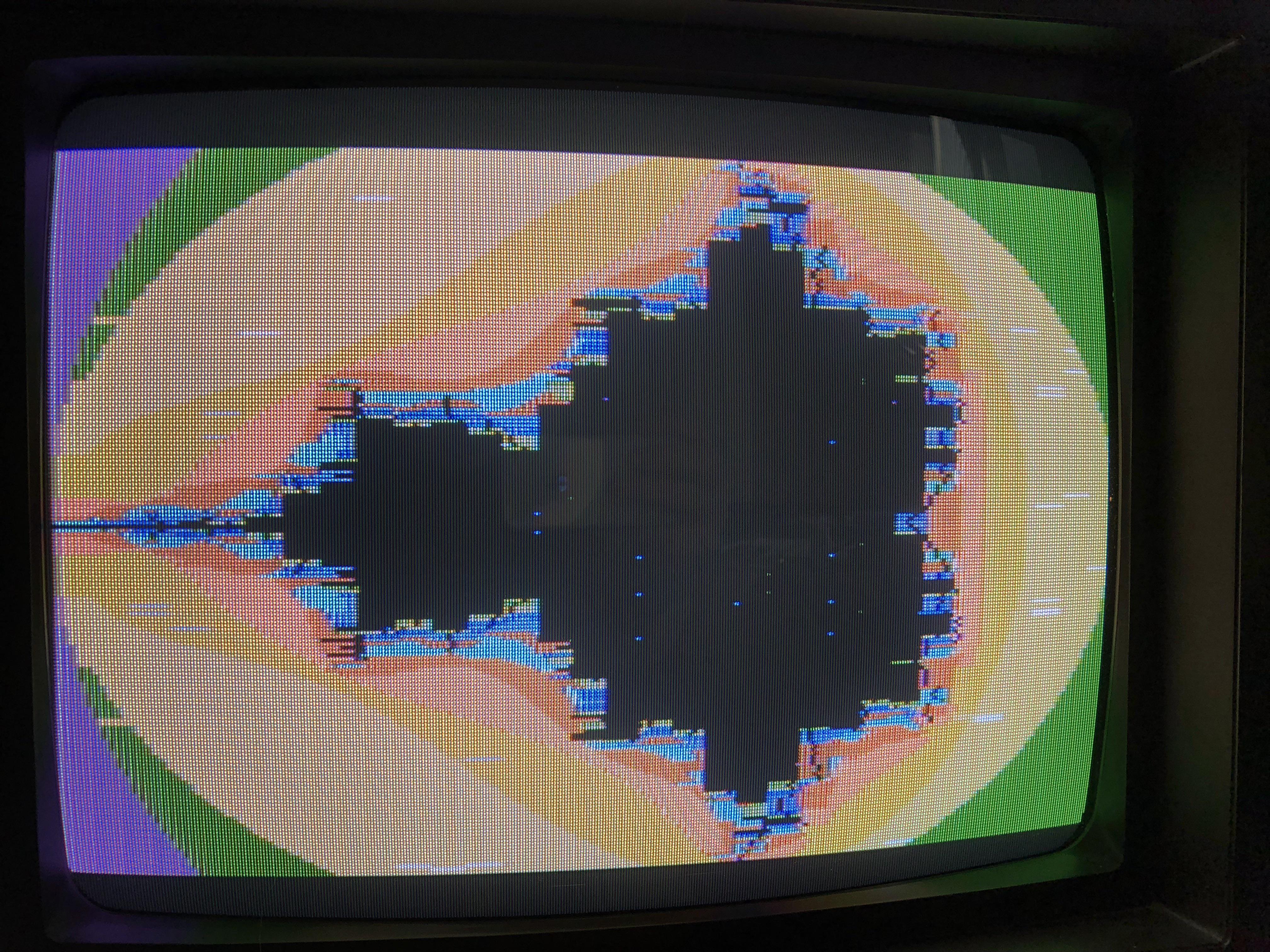
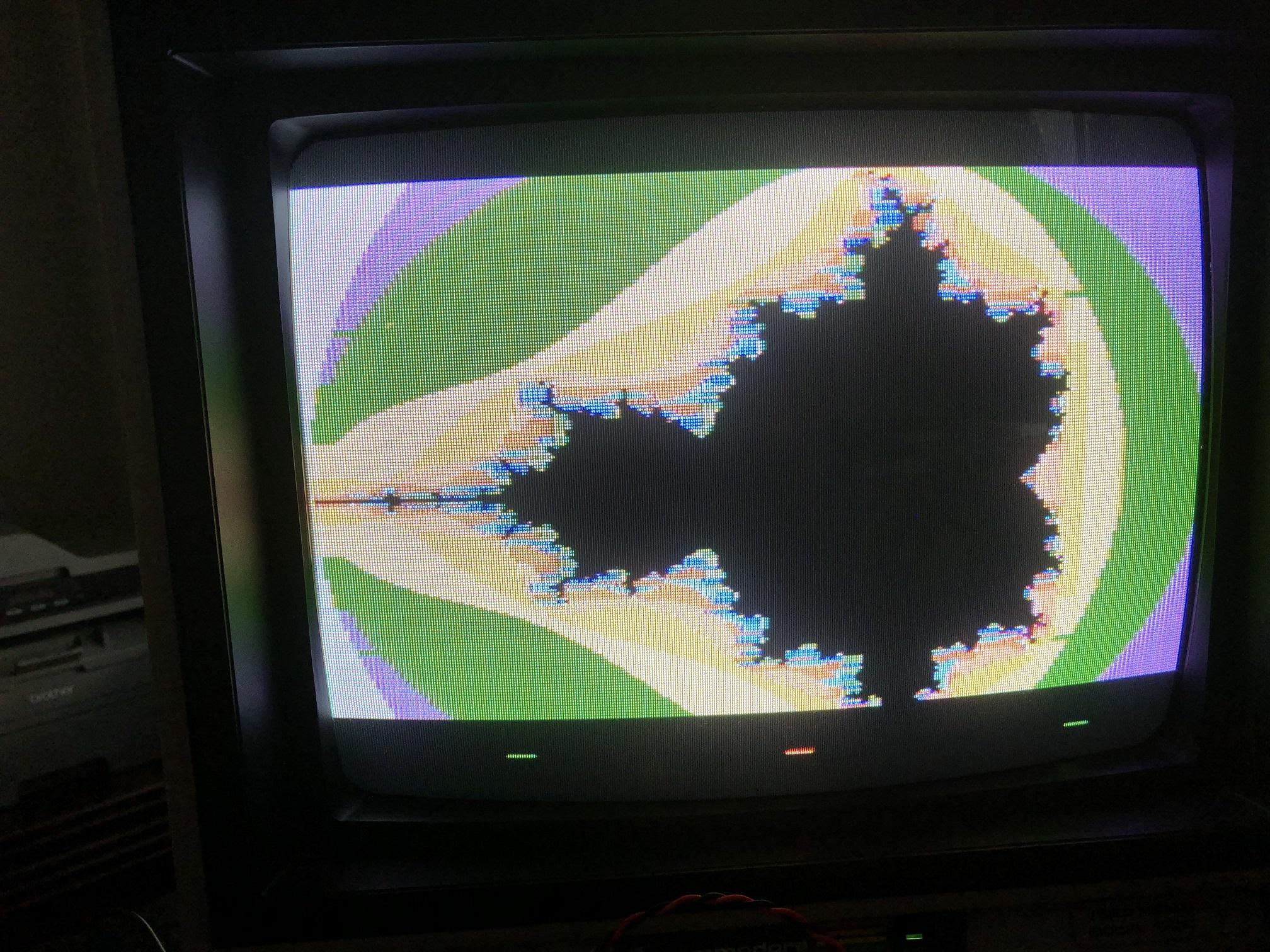
Ordered and built a board, though the video output was all pixels (more like a grid), with darker grey on the left 1/5th or so while running the Mandelbrot example. Guess I've got some debugging to do...
--
You received this message because you are subscribed to a topic in the Google Groups "RC2014-Z80" group.
To unsubscribe from this topic, visit https://groups.google.com/d/topic/rc2014-z80/0m0kbzIJ3tw/unsubscribe.
To unsubscribe from this group and all its topics, send an email to rc2014-z80+...@googlegroups.com.
To post to this group, send email to rc201...@googlegroups.com.
To view this discussion on the web, visit https://groups.google.com/d/msgid/rc2014-z80/3b51578d-d251-4d62-a8d6-7d0276895736%40googlegroups.com.
Thomas Jager
On Tuesday, 3 July 2018 23:24:28 UTC-4, J.B. Langston wrote:
Can you take a picture?What assembler did you use, and how are you running it?What clock speed are you running?
On Tue, Jul 3, 2018 at 10:21 PM Thomas Jager <tho...@thomasjager.ca> wrote:
Ordered and built a board, though the video output was all pixels (more like a grid), with darker grey on the left 1/5th or so while running the Mandelbrot example. Guess I've got some debugging to do...--
You received this message because you are subscribed to a topic in the Google Groups "RC2014-Z80" group.
To unsubscribe from this topic, visit https://groups.google.com/d/topic/rc2014-z80/0m0kbzIJ3tw/unsubscribe.
To unsubscribe from this group and all its topics, send an email to rc2014-z80+unsubscribe@googlegroups.com.