Constructed Devices Show & Tell

Steve Gibson

Myron
I am getting ready to make an attempt at making one of these myself. I can solder things and I can read a drawing. But that's about it. I have a couple questions.
I think I would need some type of board with holes in it to solder to. Any suggestions?
My other question is that I assume the CPU is programmed on the development board and then moved to my circut board. shouldn't I use a socket so I would have the ability to take it off and re-flash it? I might have some old memory cards or video cards that I could de-solder.
Am I on the right track?
Myron
below is my parts list:
1 - board with holes in it (BREAKOUT BOARD) NEED PART NUMBER?
2 - batteries 9v GOT
2 - 9v BATTERY HOLDER http://www.digikey.com/product-detail/en/968/968K-ND/151577
2 - 445-8516-ND http://www.digikey.com/scripts/DkSearch/dksus.dll?WT.z_header=search_go&lang=en&keywords=445-8516-ND&x=16&y=16&cur=USD
1 - 445-3752-1-ND http://www.digikey.com/product-detail/en/TSL0808RA-221KR54-PF/445-3752-1-ND/1913616
1 - CPU GOT ?? http://www.digikey.com/product-search/en/programmers-development-systems/eval-and-demo-boards-and-kits/2622039?k=MSP430G2553
TEXAS INSTRUMENTS
1 - High MOSFET driver http://www.digikey.com/scripts/DkSearch/dksus.dll?WT.z_header=search_go&lang=en&keywords=TC4421AVPA&x=0&y=0&cur=USD
1 - 497-7288-ND http://www.digikey.com/product-detail/en/L78L33ACZ/497-7288-ND/1038304
1 - SWITCH GOT
1 - TWEETER http://www.ebay.com/itm/ProCraft-Piezo-Tweeter-70-Watts-/261114510098?pt=US_Speaker_Parts_Components&hash=item3ccba33b12
1 - CASE Maybe an old 6v large battery flashlight.
1 - ?SOCKET FOR CPU?

tco...@gmail.com
Also, you may find the "multipurpose PC board" easier to work with, as it comes with holes that have pads and some interconnects already, search "276-150" on radioshack or look for it on the web from any electronics supply site.

Mike King

coo...@gmail.com
On Friday, January 4, 2013 9:35:14 AM UTC-8, Steve Gibson wrote:
Steve Gibson
coo...@gmail.com
Steve Gibson
I have soldered up the components, but have not been able to get sound yet. Does the U1 side on the schematic indicate the indent on the top of the MOSFET chip?

/Steve.

Kindanyume
(no such fancy tools handy here)
Steve Gibson

Whistle1940
Here is my first attempt.
The circuit is v2.2 and the container is a Mainstays Mix & Serve Container 2 cup capacity MS043-430-10-19 from Wal-Mart. The notch in the screw on cover is due to a pour spout on the container.
I cannot hear it working (72 years old, worked in construction, had tinnitus since childhood). But a twenty-something said it was irritating and the dogs do take notice. I have ordered some boards from BatchPCB and will build a v2.2.2 when they arrive. The frequency of a 1mh build showed 17khz on a Fluke meter so I am using a 1.5mh inductor (14.6 khz on the Fluke) .
Steve Gibson
Everyone,
Here is my first attempt.
The circuit is v2.2 and the container is a Mainstays Mix & Serve Container 2 cup capacity MS043-430-10-19 from Wal-Mart. The notch in the screw on cover is due to a pour spout on the container.
I cannot hear it working (72 years old, worked in construction, had tinnitus since childhood). But a twenty-something said it was irritating and the dogs do take notice. I have ordered some boards from BatchPCB and will build a v2.2.2 when they arrive. The frequency of a 1mh build showed 17khz on a Fluke meter so I am using a 1.5mh inductor (14.6 khz on the Fluke).

Brian Hall
1 - board with holes in it (BREAKOUT BOARD) NEED PART NUMBER?
Brian Hall
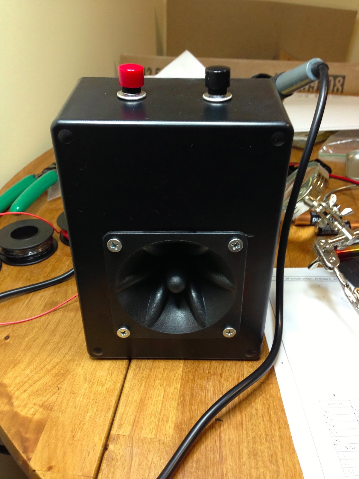
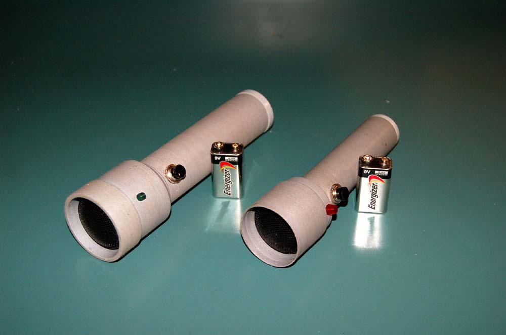
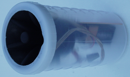
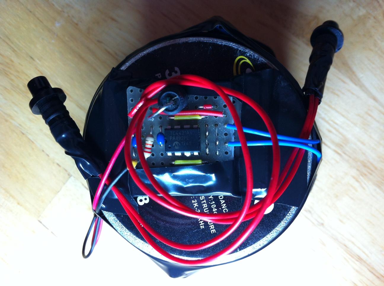
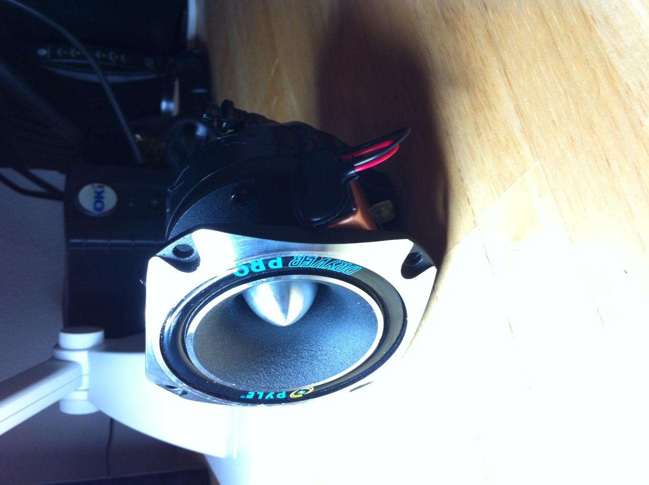
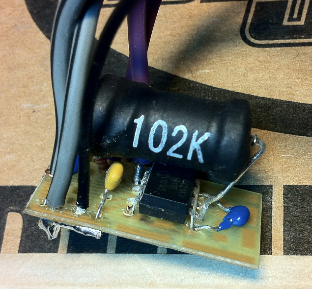
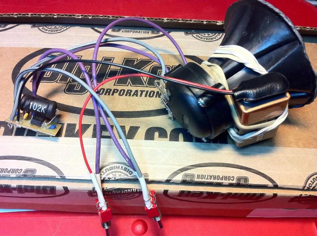
Here's my first attempt at building v.2.2.2. I used an empty flashlight body and mounted the tweeter about 1/2" below the end where it flares out slightly. I had to remove a lot of the plastic trim around the tweeter with a hacksaw and a file. Also, be careful with the wires connecting to the tweeter--both leads broke off while I was working on them. I had to re-solder the leads back on twice. In hindsight, I probably should have found a larger diameter pipe to mount the tweeter further down, allowing it to resonate better and give it more directionality. The pushbuttons I used are Digikey P/N: EG1900-ND (http://www.digikey.com/product-search/en?x=14&y=20&lang=en&site=us&KeyWords=EG1900-ND), and I really love them. I plan on using this same pushbutton in any further builds, and for other projects. I love how they feel and react.
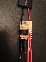
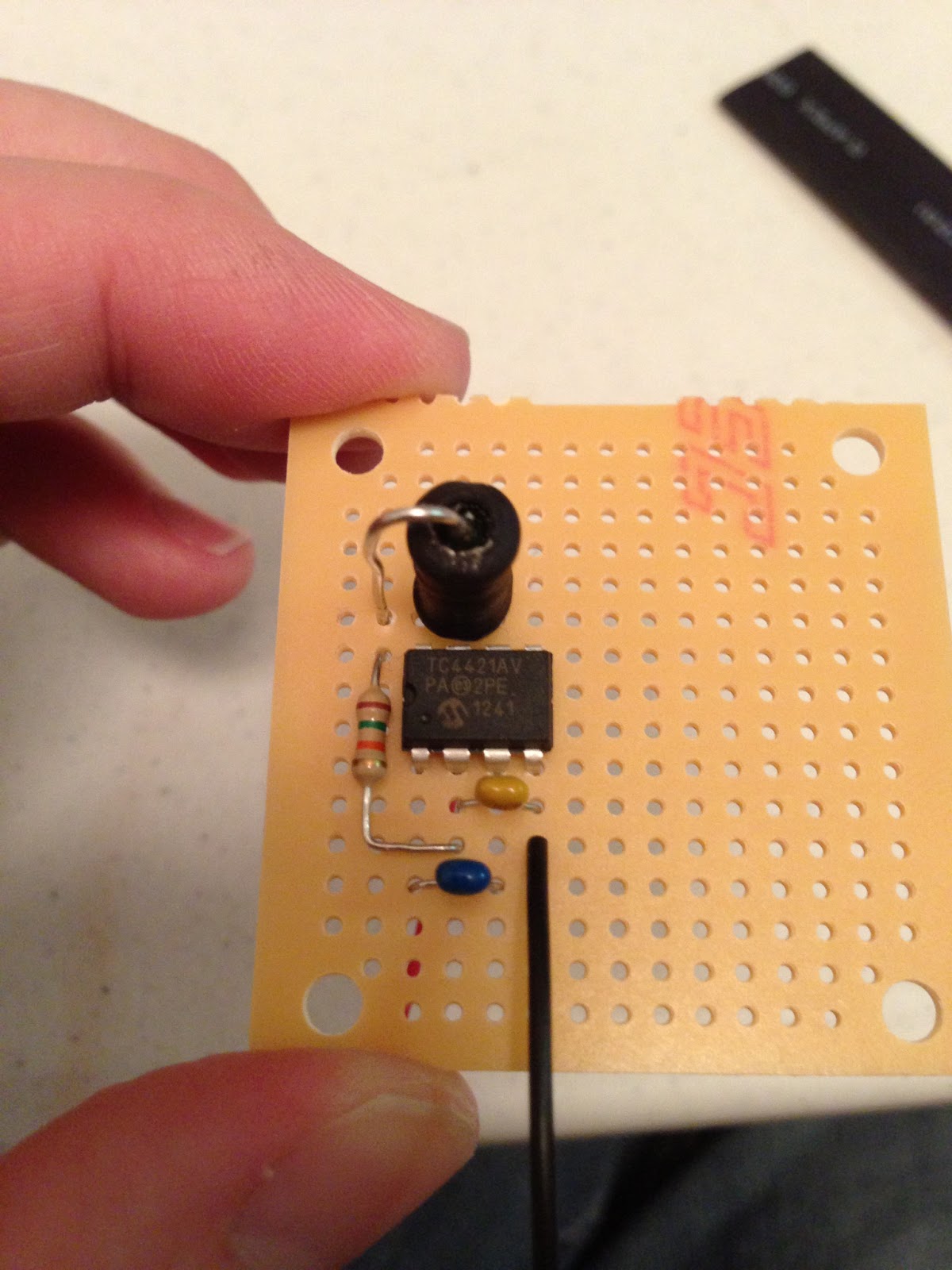
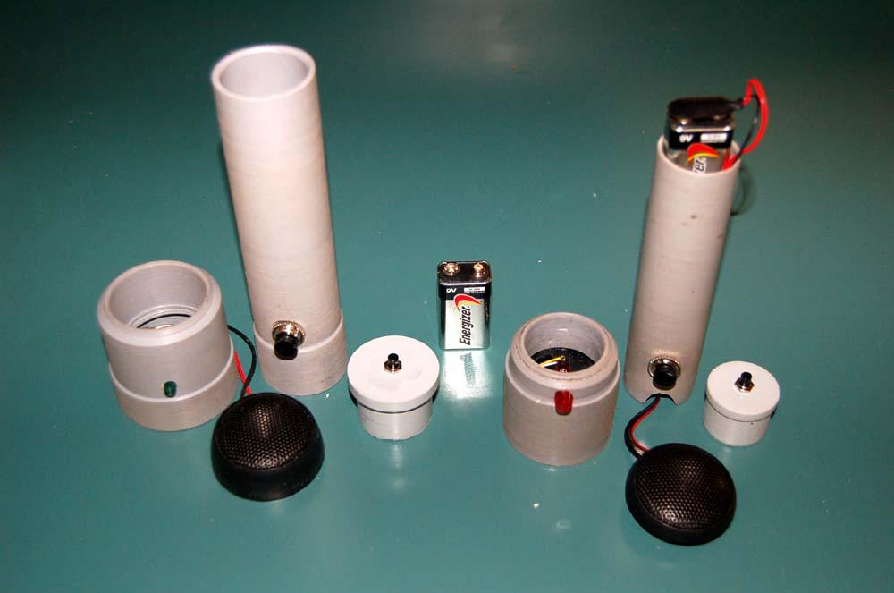
Here is a photo of all of the components before mounting in flashlight enclosure:


There is a hole in the bottom of the flashlight case for battery access. The flashlight originally came with a textured, rubber sleeve (not pictured) that fits over the entire flashlight, which I put over the bottom to hold the battery in. I had to cut a small area for the buttons to poke through the rubber casing. I used Gorilla Glue (I love that stuff) to hold the buttons and the tweeter in. Thinking of creative mounting solutions is one of the funnest parts of building this!
coo...@gmail.com
LOUD!!!...Put your head phones on for the lower frequency as it has a very high pitch sound.
The trick to getting the lower frequency is to hold both buttons down.........I know, some of us are slow on the uptake. The test
button was a great design feature.
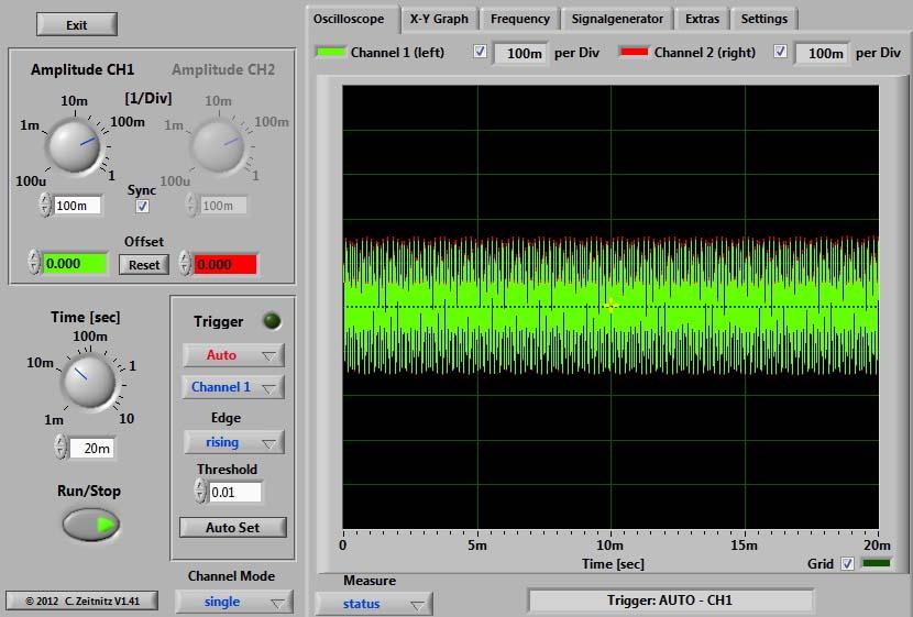
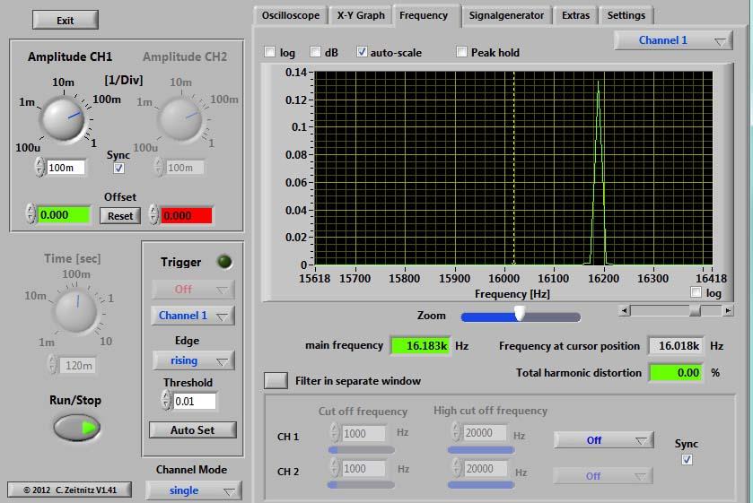
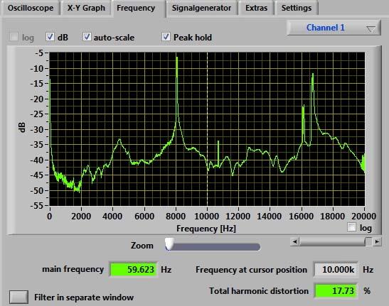
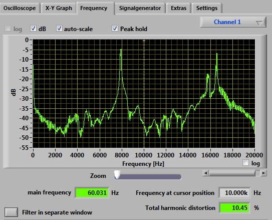
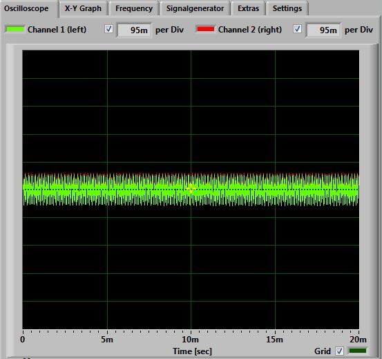
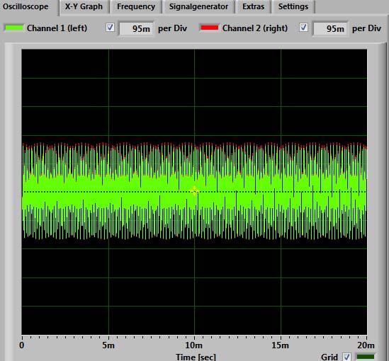
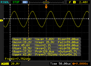
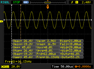
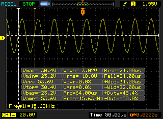
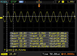
Here are some comparisons between the small 1.5" and large 3" speakers at 18" from mic.
Frequency's are with both buttons held down showing 8 & 16+ kHz. Both the same.
Oscilloscope is using high frequency button only. I don't know the significance of the different widths. They get narrower as the
distance increases.
I tried it on a older dog. He just looked at me! Older dogs must have hearing issues too. A raven flew away.
On Friday, January 4, 2013 9:35:14 AM UTC-8, Steve Gibson wrote:

Sean
Sean
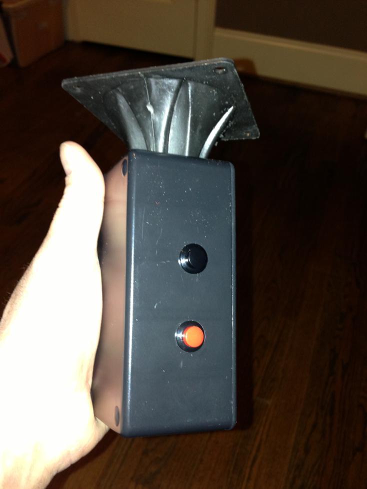
> Here is my build of the v2.2.2 TrebleShooter. I've got no experience soldering up electrical components at all as you will be able to see. It took about 2 hours to make up the board. The wife and kids tell me it works really will and loud. Pressing the test button gives me an instead headache so that works well. The box is made out of 3mm MDF, wood glue and 6mm dowel rod on the inside for added strength. The box is 200mm long X 91mm wide X 91mm high. I used an old cupboard handle I had laying around for a handle. On the right is the 16khz tone button and the left is the 8khz test button. I've still got a little more work to do on it but for the most part it is done. Now to wait and try it out on the next doors dog and see what happens.
>
>
> TrebleShooter Pics

Steve Plegge
qualify as dogs. You can't put a saddle on a dog and ride it...
Woof
On the Internet, no one knows you're a dog. [Dogs Rule!]
Steve Gibson
Got a chance to try mine out. My brother in law came around with his dog. A Irish something X, 8 months old. Not really sure what the dog is. It's the size of a small horse. Anyway I was sitting on my front verandah and the dog was sitting, back turned to me, about 2 - 2 1/2m away. I gave the 16khz button a quick press (0.2 seconds). The dog heard it as she turned around to see what the noise was. So I pressed it again for 1 second. She turn her head in a inquisitive look but it never seem to bother her. At this point she started to walk towards me, so I've press the button and held it on. She walked up to the tweeter, sniffed it for a couple of seconds and then laid down at my feet. So I hit her with the 8khz tone. She heard it but she never lifted her head. Looks like my fist test was a failure.
Kindanyume
Indeed.. my friend had a massive IWH yrs ago.. the dog not even
really chubby and was weighing in at over 240lbs. Almost double my
wight at the time!
I gotta see if I can find some pix of that monster... oh and no one
tried to break into his place LOL
Kindanyume
of that nature.

Vinny Valdez
> I think our notion that the thing would bother a dog from a significant --
> on a level of pain to induce it to cease barking -- is likely to be proven
> wishful.
>
> /Steve.
Vinny
Steve Gibson
My apologies that I am not fully caught up on the research, but has the possibility of the dog(s) actually wearing the device been considered? Our 2 dogs patroll our permiter annoying everyone and everything and I don't always have line of sight from my office window. This makes working from home very difficult at times. A remotely activated TQC collar would be wonderful.
Vinny Valdez
When I was writing that I had the same thought. Though I was thinking of having a bark-response approach, which would be VERY easy to do since the dog's own bark would be SO much louder than other ambient sounds. So false triggering would not be much trouble. And with something as small is the little Pyle surface-mount tweeters... it could be VERY small. In fact... we could use BOTH of the little tweeters, one on each end./Steve.
--
Vinny
Steve Gibson
That would be fantastic Steve, I would love to test anything for you. I will submit my full story via your feedback link.


Steve Cirelli
Steve Gibson
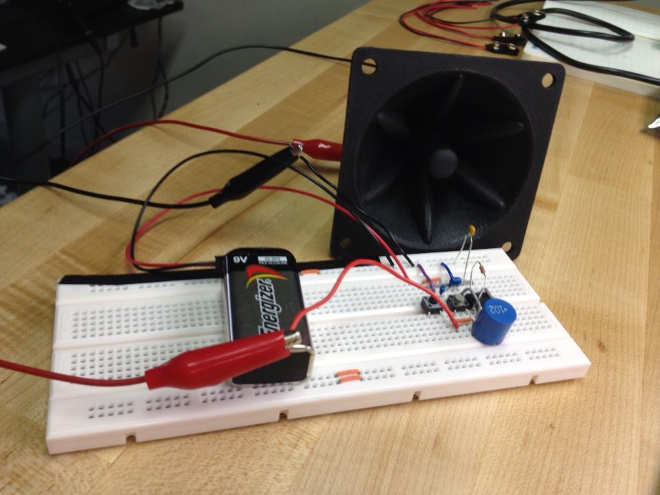
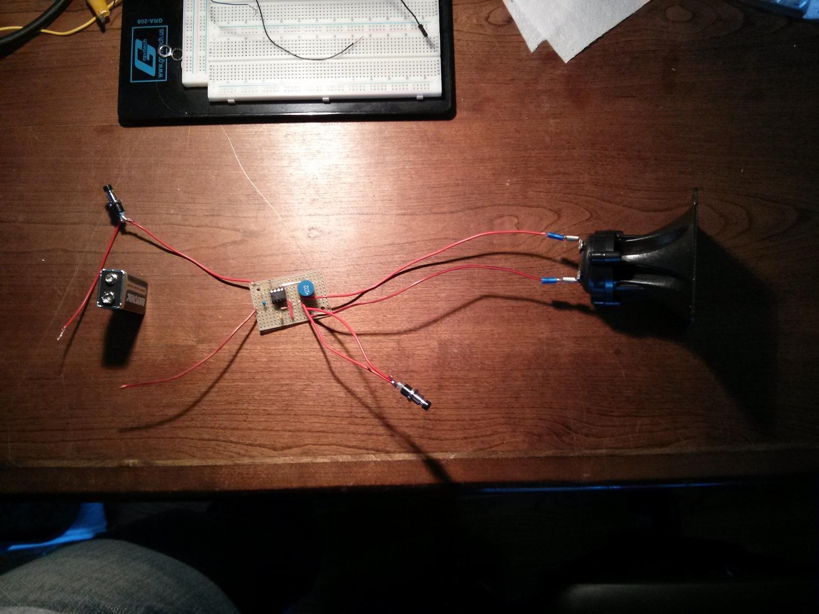
No box yet, so, I just taped everything down.
My v2 will use a smaller speaker, assuming this one has an effect.
Cant wait for morning!!!
Steve Gibson
I got a chance to breadboard v2.2.2 before I went snowboarding Friday. Just now getting a chance to post some results.I have two huskies, very well behaved never make a sound. I'm actually building this because my mom has two very annoying Pomeranian's, not for my dogs. Anyway, they were in the room while I was assembling. When I testing it (not directed at them) they didn't seem to care. One ever came up and sniffed the tweeter. So I'm not sure if v2.2.2 would work on my dogs.To be honest I'm not willing to test it any further on my dogs. I have sensitive hearing and my ears were ringing after the testing. My dogs will walk up to snarling barking German Sheppard's and Rottweilers without blinking an eye and try and sniff them. So it's possible that the noise just doesn't scare them.I'm going to mount everything on perf board then I'll try it on my mom's Pom's and post the results. They are much more skittish, so hopefully I'll get a reaction from them.
brian...@gmail.com
Yep. Ordered the wrong one originally, the giant magnet should have been a giveaway. I ordered 3 different types today to play with form factors once they arrive. Switching out the ‘horn’ will be the easiest part of the build.
Kindanyume
dumb asses sent similar models.. claiming they are "piezo like" even
when asked explicitly if they were piezo or not. So much for the
sales dept in that company having a clue lol
Oh well I'll use the samples elsewhere.. or maybe see if I can mod the
horn portion to use on the pyle SM model
Steve Gibson
ahh and meanwhile.. the samples from one MFR arrived for me.. and the
dumb asses sent similar models.. claiming they are "piezo like" even
when asked explicitly if they were piezo or not. So much for the
sales dept in that company having a clue lol
Oh well I'll use the samples elsewhere.. or maybe see if I can mod the
horn portion to use on the pyle SM model
Kindanyume
the "simple" version

tr...@smartlivingenergy.com
Steve Gibson
Here is my 1st attempt an V2.2.1 . I can hear both tones, the higher when the red S1 button is press and lower when black S2 pressed.My dog looks around at me, gives me east sh** eyes, and walks away.It is not as loud as I would like, and I would like it to work from longer distances (tuned 1 1/2" pipe rifle), but it was a fun build.

Steve Gibson
I built the first of ten last night. The 2.2.2 plan worked great!
Jon Katayanagi

sigpoggy


Kyle Smith
sigpoggy
Steve Gibson
I just measured and got the same results as when it was breadboarded:8.5KHz is 112db at 1 meter17KHz is 103db at 1 meterMeasurements made with iPhone app which is not calibrated (ball park calibration of "quiet space"), and at a distance of about 25 feet so it wont peg, then calculated for 1 meter. The drop for the higher frequency appears not to be due to freq response on the phone, the output voltage across the speaker has a corresponding drop.
sigpoggy
The app I'm using is Decibel 10th by SkyPaw Co, Ltd
sigpoggy
sigpoggy
sigpoggy
Steve Gibson
Interesting!
So you're saying that 50K was louder for you than the original 22K ??
I was optimizing for waveform purity and absolute amplitude, not absolute loudness... So perhaps there's a better strategy. :)
Brian Hall
Brian Hall
sigpoggy
Steve Gibson

Álvaro Prieto
sigpoggy


stede....@gmail.com
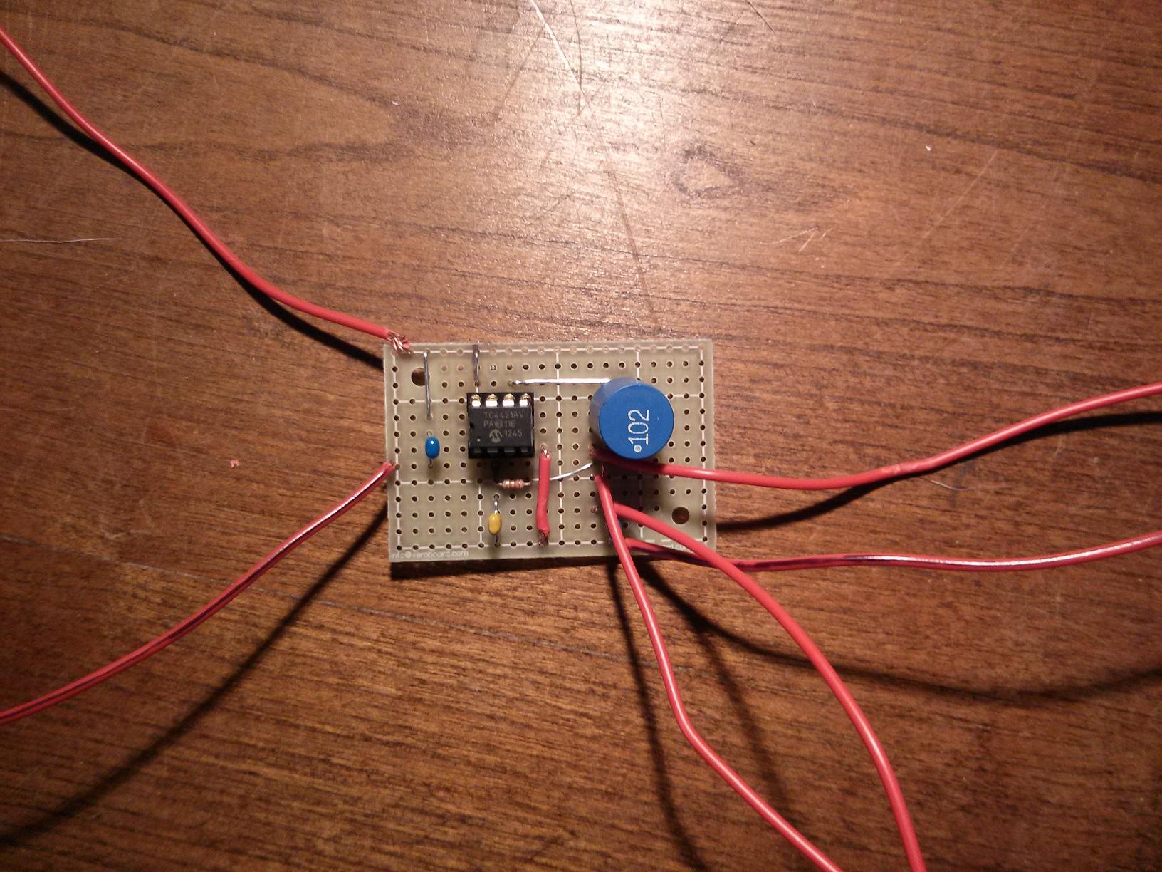
OK, so I've been lurking and getting up to speed on the design while doing some other projects.
My MOSFET driver came today so I built up a test circuit of v2.2.2 (minus the power bypass cap)...

sigpoggy
Steve Gibson
I wonder if the click is due to the missing cap.
Steve Gibson
I have taken the horn off mine and one problem is the horn holds the speaker in place with regards to its back housing and terminals. Either that has to be glued or clamped (or eliminated?). The diameter of the speaker is about 1.5".

Stephen
Great work and great photos..thanks for posting.
Slightly puzzled by the inductor, seems different to the one suggest by Steve in v2.2.2 any reason for this ?
Regards Stephen
Jon Katayanagi
Steve Gibson
Great work and great photos..thanks for posting.
Slightly puzzled by the inductor, seems different to the one suggest by Steve in v2.2.2 any reason for this ?

hausm...@gmail.com
Posted yesterday in the Q&A thread while I was trying to get it to work on the breadboard. I got it working and put it on perf board this morning. It went well and I am happy. I would do the project box different next time, but this was a good first time at making anything. Have not seen any barking dogs yet today, but maybe later. Attached pictures of my progress.


duf...@gmail.com


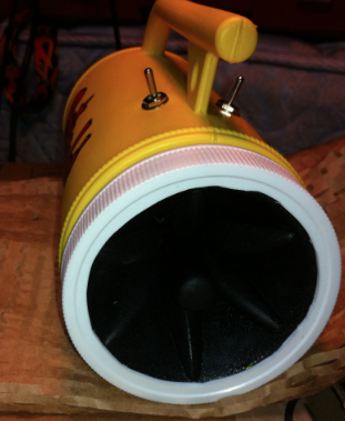
 Hello all. I wanted to share my build. It is version 2.2.0 residing in a 3D printable package.
I made a few mistakes along the way. I ordered an absolutely massive push button on accident but it looks nice and inviting on the top. The cavity in the handle was just barely big enough to fit everything. I can't really get the battery out of the bottom without taking the handle apart. I didn't create any holes for the button or the tweeter hook-ups so I had to drill. If you have ever drilled a 3D printed object you know it just kind of splinters with a normal bit. I printed on a Thing-O-Matic which are an older technology and don't produce quality prints most of the time. I had to do some Dremel-ing to get things to fit.
All that said, I think it turned out pretty well. I've attached the 3D files if anyone wants to print them or improve them.
-Griffin


Thomas Couey
Steve,
I know that you were looking to profile as many speakers as you could to find out if the less expensive ones worked as well as the premium ones. Forgive me if you already have this data, but I haven't had time to completely read through all the posts. Anyway, I just got my speakers today as I had to have my parents on the mainland re-mail them to me because the seller will not ship to Hawaii (very annoying).
I used one of these: 4 Pieces of Piezo Tweeters Replacement for KSN1005A Motorola T1005-4
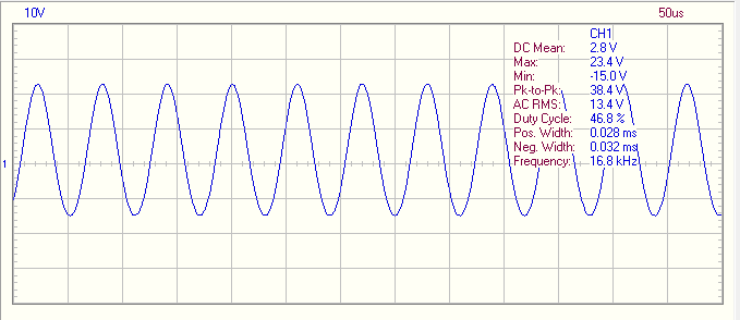
And attached is a scope trace of the output. I don't have a decibel meter, so I can't speak to the actual volume, except that it's very loud.

In case you can't see it in the re-sized picture, it's 44.8V peak-to-peak, at 16.81kHz. It looks like it has a bit of a DC component, but I suspect that's to be expected. I didn't measure the capacitance or resistance on them, but if you want that data, I can.
I literally just received these and threw the parts on the breadboard, so I don't have a finished unit to show off yet, but I'll post a pic when I do.

Steve Gibson
Steve Gibson
Thomas Couey
BB400 Solderless Plug-in BreadBoard, 400 tie-points, 4 power rails, 3.3 x 2.2 x 0.3in (84 x 55 x 9mm)
/Tom.
stede....@gmail.com
Hi stede,Have you taken voltage measurements across the tweeter?
stede....@gmail.com

Thomas Couey
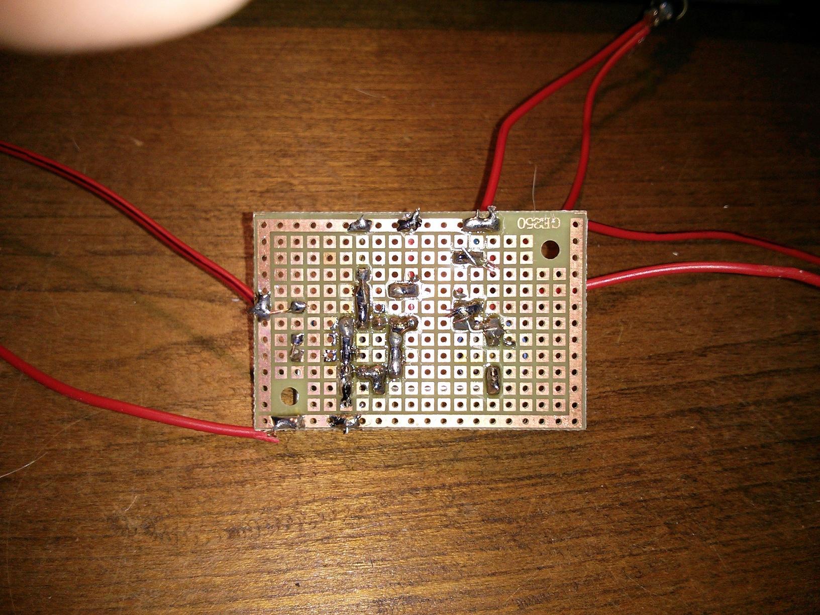
Here it is on a protoboard:

And the back (I haven't cleaned off the the flux yet...):
I guess I need a case now.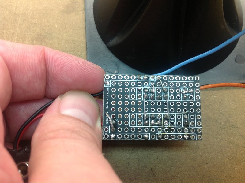
I tested it on the neighbor's dog with somewhat disappointing results. There is foliage and a vinyl fence between the sidewalk and the backyard where he is. It did sound like he backed up a little, but he was still barking. I pulsed it for about a second after each bark, but he kept on. I ended up with a headache and ringing ears. I think I'll use earplugs next time I use it (even outside, pointed away from me).
I noticed that the freq. shifted up a few hundred Hz on the soldered version (just over 17kHz). I wonder if I should add a little capacitance to the output to drop it down a few hundred cycles. Maybe I'll see if that makes it any more effective. Worst case, maybe I'll just drive the tweeter with a square wave and see if that is more annoying.
-Tom
Steve Gibson
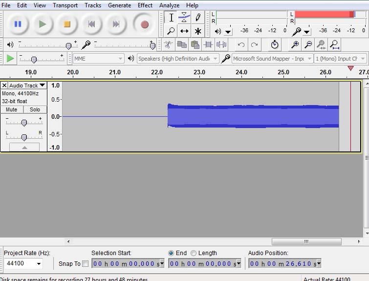
Just recorded the output on my C01U at my desk. I attached a sample of the beginning and end of each waveform - you can hear the click sound and see the un-loaded resonant frequency. I'm getting closer to 8.2kHz and 16.4kHz looking at these.
This is the startup of the oscillator (48kHz sample rate)
Steve Gibson
Here it is on a protoboard:
Steve Gibson
Steve Cirelli
Steve Gibson
Here's pics of my first attempt at v2.2.2. Been forever since I soldered anything so it's ugly but it works. Now I need to buy a battery holder, and make a case for the entire thing.
stede....@gmail.com
The problem is... unfortunately... that 48khz is not a fast enough sample rate to capture the true waveform of a 16khz sine wave. That sample rate is only three times the period of the waveform you are trying to capture. So you'll only be able to see three points along one entire cycle of the sine wave. You CAN get a feeling for it -- absolutely -- but not a picture of the waveform. It's just moving too fast. (The lower-frequency mode ought to be better.)/Steve.


Steve Gibson
Thomas Couey
1 Panel Of Double -Sided Prototype PCB, 576 Holes (CS-BP002)
The price is $1.99 with free shipping, if you use the Hong Kong Post Office ;-) I thought you'd like that. Everything I've bought from them came through Hong Kong Post with no problems, it's just a little slow (customs and such).
One thing to note is that they're break apart boards, so you actually get four for that $1.99. I've left them connected for larger projects, but for things like this, the quarter panels are great. So, it works out to $.50 a board, if you can deal with the shipping time (anywhere from about 1-3 weeks, depending).
When I bought them on eBay (a while back), they came in 5 packs:
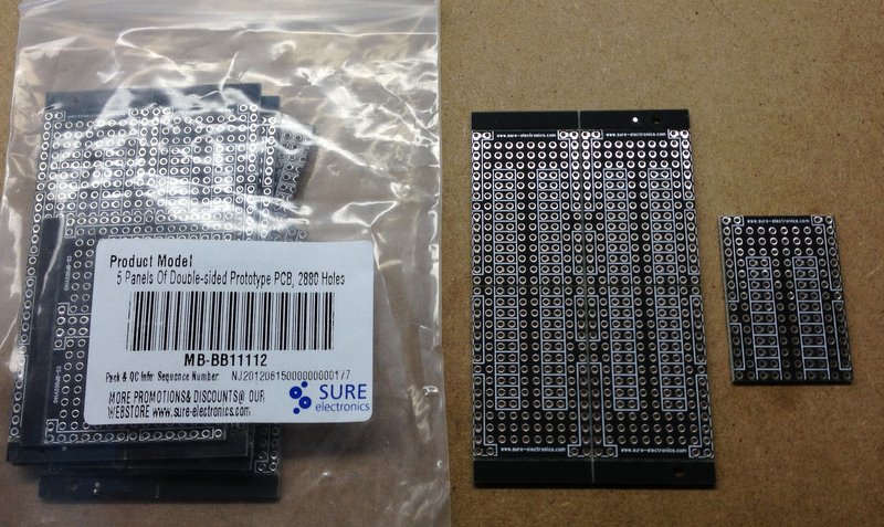
-Tom
Thomas Couey

44.6 VAC pk-pk, 15.0 VAC RMS, 17.07 kHz, at present.
I've confirmed that it doesn't seem to bother my neighbor's dog, so I might try a 555 driving a transistor with a 27V power source (something closer to your original PDK). I may need to look at a different transducer though.
-Tom
Thomas Couey

sigpoggy

Kindanyume
sad but very true :(

g...@watkins-home.com
Can't wait to test it with the neighbors dog.
stede....@gmail.com
g...@watkins-home.com
Wait, I tried another speaker (bought 4) and I get about 15,800Hz and 8130Hz. I did not expect that.
#3 gives me 15,600Hz and 8,130Hz
#4 gives me 15,800Hz and 8,130Hz
I guess 1 of 4 is out of spec?
I would like to increase the frequency so that wife and kids can't hear it.
Question, if the frequency is too high to hear, can it still cause hearing damage? Silent but deadly (damaging)? :)
Thomas Couey
Yes, high frequency can damage your normal hearing. It has more to do with the volume (decibels) than the frequency.
Noise-Induced Hearing Loss (NIHL)
Kyle Smith
Steve Gibson
So, capacitance. The only thing I had handy was another 4700pF so I connected it in series which gives me 2350pF and I wound my pot up to 24.5k to retain my 8vp-p input and I got... 74.5dB. Dropping down to 22...@8.5Vp-p on the input I topped 75dB in the trap @50Vp-p on the tweeter.
Also, any lower resistance and I could see the clipping on the scope as it reached 8.7 which jives with the datasheet for the 4421 (Vdd-.3V max).
Steve Gibson
I used xoscope (software) and it shows about 13,000Hz and 8,000Hz. I tested a 15,000Hz sound source and xoscope reported 15,151Hz, so I think xoscope is giving reasonable results. So, if 13,000 and 8,000Hz do not "train" the dog, what should I change to increase the frequency?
Wait, I tried another speaker (bought 4) and I get about 15,800Hz and 8130Hz. I did not expect that.
#3 gives me 15,600Hz and 8,130Hz
#4 gives me 15,800Hz and 8,130Hz
I guess 1 of 4 is out of spec?
I would like to increase the frequency so that wife and kids can't hear it.
sigpoggy
stede....@gmail.com
Ah... that's better. But getting it up to around 70Vp-p would be perfect.Have you measured the voltage on your 9v battery while the sound it being generated? I realized that my testing had been done with my lab bench supply and not enough testing with an actual 9v transistor radio battery. I'll be switching to pure battery power from now on.
/Steve.
sigpoggy
Steve Gibson
Wow, just received the Goldwood GT-1005. What a HUGE difference it makes compared to the Pyramid TW105! It's about 20Vpp more, which is definitely noticeable.
Steve Gibson
I notice a big difference in frequency. I have found the lower the frequency the higher the amplitude.
Steve Gibson
I tried a couple values for C2 down to 1000pF (where the circuit stops resonating, BTW) and I tried a slightly larger and smaller inductor (I used speaker crossover parts with very low DC resitance, <0.5Ω). I don't see much more than 50vp-p at any point.The battery drops as much as 0.4V under load. Reducing the input voltage with larger values of R1 reduces the voltage drop (less current). If a nominal 9V battery has a Ri of 1.5Ω that should indicate 600mA load, but the actual power draw is an order-of-magnitude less at ~62mA. (Then there is also the possibility I suck at math).So there's that...
Steve Gibson
I have been playing with the circuit and have come to the conclusion that the output frequency is the main determiner of the output voltage across the tweeter. Playing with R1 an d C2 have a small affect on amplitude and frequency. Picking a value for C2 then tweaking R1 with a pot you can find a sweet spot but you only gain a few volts.
Adding capacitance across the tweeter to change the tank frequency causes the amplitude to increase dramatically as you go down in frequency. Again, R1 C2 adjustments at lower frequencies cause minimal change.
Pulling the frequency down to 15.7 kHz and tweaking the feedback gave me a high of about 45vpp - (vs 39vpp at 16.9kHz). Don't have other inductors to play with, but seems that would not really change the dynamics.