STOP THE PRESSES!! NO MICRO NEEDED!!
已查看 1,681 次
跳至第一个未读帖子

Steve Gibson
2012年12月14日 16:16:232012/12/14
收件人 portable-so...@googlegroups.com
Everyone...
THIS WORKS WONDERFULLY!!
You may notice that there's something conspicuously missing... the micro controller!
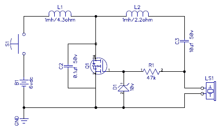
Over in the "Auto Tune" thread, Bill McFadden and I have been enjoying a dialog about the possibility of getting the circuit to oscillate all by itself. He ran a simulation that said it would. The more I thought about it, the more obvious it was that it would do SOMETHING, since the MOSFET is wired up as a high-gain inverter, and it's driving a tuned circuit that will have a strong voltage-phase delay. So I simply took the tuned output and coupled it back to the MOSFE's input with a series resistor and zener clamp to protect the MOSFET's somewhat delicate gate.
It oscillates like a bat of of hell!!
It produces a MORE PURE HIGHER VOLTAGE sine wave than when the system was being driven by the processor. And... it (currently) PREFERS oscillating at about 14.2 khz!!
Furthermore, exactly as would be predicted, as the piezo element in the tweeter heats up and changes its reactance, the whole system adjusts its frequency smoothly and automatically to remain in the "sweet spot" of the current components.
It is a WIN WIN WIN!! And this result demonstrates the power of open collaboration among smart people. :)
A few notes:
1. You may note that the resistance of L1 is now about twice that of L2. That's a change I silently made a few days ago when I was thinking about how much time the MOSFET is spending "ON". This modification is non-critical, but it will reduce WASTED power in L1 and yield a longer battery life... likely without any reduction in output power. (I wasn't keeping this a secret, I just wanted to put as much possible into the next design update.) This is new L1 is DigiKey Part No. 445-6494-1-ND.
2. The values of the two new components -- the 10volt Zener and the 47k resistor -- are both non-critical. They are both there only to protect the MOSFET's gate. The zener needs to be above the MOSFET's full turn-on gate-drain threshold voltage, but also safely below its gate breakdown voltage. So anything between 3 and 9 volts. (I should be using a lower voltage zener and I will in the final design... I just didn't have one handy.) The resistor is there to limit the current through the zener -- both when it's clamping the gate at its positive "zenering" voltage, and also when it's clamping the gate in its forward biased mode at a low negative voltage.
This all JUST happened... so you would be best advised to wait
through the weekend so that I can settle down and get it tuned
for minimum power consumption and maximum output.
And if you're wondering about the role of, and need for the micro... I do still plan to use it in my design to control the "blast duration" and "blast radius" (volume) of the device. But if you want a simple push-to-blast solution... the micro is no longer needed!
One further note: Using the switch to switch the battery COULD now create some arcing in the switch since you'll have both high amperage and often high voltage there. So what I once said about the switch being "anything" doesn't apply in this revised usage.
/Steve.
Steve Gibson
2012年12月14日 16:30:312012/12/14
收件人 portable-so...@googlegroups.com
Update:
I let the circuit alone for an hour while I wrote a note to Bill McFadden, updated the schematic, and posted the news above.
I just touched it off after the batteries had recovered and the piezo had cooled off... and we're at a 70vp-p sine wave at 15.1 khz.
So the 14.2 khz I reported was after some "warmup" of the system. How neat is that!?!?
/Steve.

book...@gmail.com
2012年12月14日 20:15:262012/12/14
收件人 portable-so...@googlegroups.com
So if I understand correctly, the possibility of playing with the frequency ("wiggle" I think you said), to do a more annoying sound to the dog is out of the question we that new design? I loved that idea of making a more annoying sound.
Maybe we could add a second LC resonator plus a second tweeter at a different frequency? The question is still, what is annoying to a dog?

billmcf
2012年12月14日 20:30:212012/12/14
收件人 portable-so...@googlegroups.com
Steve,
That's great news.
I think we could keep the switch small and inexpensive by placing it in series with the MOSFET's gate. We'd need a gate pull-down resistor to keep the MOSFET off when the switch was open.
That should work for the simple (no microcontroller) circuit at least.
Steve Gibson
2012年12月14日 22:59:292012/12/14
收件人 portable-so...@googlegroups.com、book...@gmail.com
So if I understand correctly, the possibility of playing with the frequency ("wiggle" I think you said), to do a more annoying sound to the dog is out of the question we that new design? I loved that idea of making a more annoying sound.Maybe we could add a second LC resonator plus a second tweeter at a different frequency? The question is still, what is annoying to a dog?
I am still very early in understanding the precise dynamics of the new self-oscillating design. (I had a date with my girlfriend to see "The Hobbit" this afternoon so that chewed up many hours. But the weekend is free!! One thing I have observed, is that it appears to be possible to produce more of a triangle waveform. Such a waveform contains a large number of higher-order harmonics. And while the pooch might not be able to hear any but the 1st and 2nd, that would definitely make the result much "brighter."
/Steve.
Steve Gibson
2012年12月14日 23:19:592012/12/14
收件人 portable-so...@googlegroups.com
Bill...
I thought of that, and though I haven't tried it yet, I wasn't sure that it would "kick start" the oscillations... as follows:
If the switch were off, the 10uf ceramic DC blocking cap would be trying to get itself charged up to 6vdc through those two paths it has to ground... through any leakage through the zerner-resistor path, or through any piezo leakage. As a consequence, the bottom of the 10uf cap, which is the only source of positive voltage to fire off the MOSFET, would tend toward ground potential over time. So it might be that when the user reconnected the gate... the MOSFET would remain off.
And, come to think of it... depending upon the charge at the INSTANT the user released the button... the oscillator might not restart. Something to consider. :)
/Steve.
Steve Gibson
2012年12月15日 00:23:232012/12/15
收件人 portable-so...@googlegroups.com
More musings about the self-oscillating design...
THIS WORKS WONDERFULLY!!
I've been living with this thing in my head for about half a day now, and various tidbits are sinking in.
For one thing, we no longer technically have a "Class-E" amplifier-based design. It's a very nice and very cool design, yes. But it's no longer Class-E. This means a number of things, but one that I need to think about is the fact that the MOSFET will inherently be spending more time in an intermediate state between full on and full off. The previously valid assumption of the switching time between "On" and "Off" and "On" again being extremely short is not AS true any longer as my previous "digitally driven" design assumed. It's true that the switching interval will still be short, as the high-voltage piezo signal (60-80v p-p) swings through the slightly positive region where it begins conducting. But now we're talking about an audio frequency analog sine wave rather than digital edges with transit times in the tens or hundreds of nanoseconds realm. I don't think this represents a huge problem, but it does mean that my choice in optimal MOSFET will likely change. I'll probably choose one with a higher gate capacitance in return for a lower R(on) resistance. The higher gate capacitance won't affect us at audio switching frequencies, and with the lower R(on) resistance will come better current-handling and power-handling capabilities. And we'll tend to dissipate less power in the switch... which is a good thing too. And R(on) matters when it's fighting against a 2.2ohm L1 resistance. (Note that I think I'll be returning L1 to 2.2 ohms, identical to L2.)
Anyway... I'm just thinking out loud. I have the weekend to spend with this and I'll get it design re-tuned and optimized.
I'm really glad that I remained on the tuning issue until clarity came. Sometimes (actually, often) unexpected turns arise.
/Steve.

Thomas Trostel
2012年12月15日 11:17:022012/12/15
收件人 portable-so...@googlegroups.com
What did we end up with here? Is this similar to a Wein Bridge Oscillator?
(See the discussion of a Wein Bridge here: http://www.electronics-tutorials.ws/oscillator/wien_bridge.html)
…. more reading required!!
Is this a modified
steve....@gmail.com
2012年12月15日 11:59:502012/12/15
收件人 portable-so...@googlegroups.com
Hi Thomas,
No, what were heading toward isn't a classic Wein, because we're not operating the active amplifying element (out MOSFET) in a linear mode.
We do still fundamentally have a switch-mode oscillator. Its input is being WAY over-driven, so it's operating in a highly non-linear region and thus digital mode.
And we are still getting a voltage flyback boosting kick into our main resonating L2/Tweeter tank when L1 switches off suddenly.
I don't know what you'd call this darn thing... perhaps a self-oscillating modified class-e voltage converter. :)
Sent from my Verizon Wireless BlackBerry
From: Thomas Trostel <ttro...@comcast.net>
Sender: portable-so...@googlegroups.com
Date: Sat, 15 Dec 2012 11:17:02 -0500
ReplyTo: portable-so...@googlegroups.com
Subject: Re: [PSB] STOP THE PRESSES!! NO MICRO NEEDED!!

adrian.p...@gmail.com
2012年12月16日 04:57:022012/12/16
收件人 portable-so...@googlegroups.com、steve....@gmail.com
Steve,
I'm over from the other (digital) thread at your bidding!
With my components I'm not getting such high power as you e.g. 0.6R L1/2. About 20VAC(rms) at 16kHz but a much sweeter sound from the tweeter than with the digital version. That rather suggests that we are hitting the power handling limits of the clone tweeters. btw do you have the real Motorola ones or clones?
Clearly, the beauty of this circuit is that it is self-resonant and the components/voltages aren't critical. This removes the problem of getting the drive to suit the tank. Since I can hear all these frequencies, I really would like to get it up to about 18kHz! Given the component ranges we have that isn't easy to fix :-( Maybe two tweeters in series would help - also with power handling and directionality too?
btw The DC blocking capacitor doesn't absorb any power (if it is any good!) BUT it does create a potential divider, reducing the useful voltage across the tweeter. Otherwise, I take your point: we want all the volts across the tweeter.
Adrian/
Steve Gibson
2012年12月16日 12:22:192012/12/16
收件人 portable-so...@googlegroups.com、steve....@gmail.com、adrian.p...@gmail.com
Steve,
I'm over from the other (digital) thread at your bidding!
Welcome Adrian!!
With my components I'm not getting such high power as you e.g. 0.6R L1/2. About 20VAC(rms) at 16kHz but a much sweeter sound from the tweeter than with the digital version. That rather suggests that we are hitting the power handling limits of the clone tweeters. btw do you have the real Motorola ones or clones?
What do you mean by "0.6R L1/2" ? You don't mean that you have 0.6 ohm resistances do you?
And 20vac RMS isn't too shabby. ALL of my quoted voltages have been p-p, not RMS.
I would interpret the "sweeter" sound to mean that it's a more pure sine wave drive... which IS what I'm seeing with the new self-oscillating design.
I have both the more expensive Motorola/Philippines tweeters and several different sources of El Cheapo tweeters. For me everything works.
Clearly, the beauty of this circuit is that it is self-resonant and the components/voltages aren't critical.
Exactly. And I DO see significant resonant frequency variances among tweeters. One inexpensive Chinese tweeter liked 17.5 khz as opposed to the 15 khz of the more expensive Philippines tweeter. So I think this has been an important improvement.
This removes the problem of getting the drive to suit the tank.
Exactly.
Since I can hear all these frequencies, I really would like to get it up to about 18kHz! Given the component ranges we have that isn't easy to fix :-( Maybe two tweeters in series would help - also with power handling and directionality too?
I don't understand why your being able to hear these frequencies (as I can too) is a problem? My feeling is that it's important for us to have some visceral sense for the fact that WE are deliberately generating a VERY potent audio beam at another creature. I'm somewhat afraid of abuse of this technology since animals CAN be very annoying and people can have their emotions get the better of them. Given that the resulting "gun" is HIGHLY directional at these high frequencies (just hold the speaker at arm's length and sweep its focus past your head), the "bleed back" to the operator is, I think, a useful characteristic. And, in fact, I'm considering lowering it a bit since the Chinese clone speakers seem to have a lower capacitance.
And, moreover, the upper-end frequency response -- both of the tweeters and canines -- does begin falling off as we go higher. Just THINK of the rate at which that poor tweeter paper cone must be moving!
All that said Adrian... the very reason I am doing all of this out in the open is to create an open solution for the world. I will decide how the devices that I produce operate. But everyone else is entirely welcome to take what I have created and alter it to suit their application and wishes.
Here are a couple of VERY nice looking inductors that ought to move your frequency up about the right amount:
820uH, 440mA, 1.96ohm power inductor:
915uH, 625mA, 1ohm power inductor:
btw The DC blocking capacitor doesn't absorb any power (if it is any good!) BUT it does create a potential divider, reducing the useful voltage across the tweeter. Otherwise, I take your point: we want all the volts across the tweeter.
Of course you're right, and that's what I meant. Voltage that falls across the DC blocking cap won't be available to fall across the tweeter... and in that sense it removes available power from the tweeter. :)
My work today is looking to see whether I can reduce the circuit's power consumption. The duty-cycle of L1 is currently higher than it was at 66%. So I believe that it's wasting battery power.
I also miss (from the micro-controller approach) the ability to control volume and generate arbitrary tones. I was looking forward to using tone signalling in an eventual user-interface. So I have some more work to do! But we're definitely getting close!
Thanks for your notes and work Adrian.
/Steve.
adrian.p...@gmail.com
2012年12月16日 13:08:482012/12/16
收件人 portable-so...@googlegroups.com、steve....@gmail.com、adrian.p...@gmail.com
On Sunday, December 16, 2012 5:22:19 PM UTC, Steve Gibson wrote:
What do you mean by "0.6R L1/2" ? You don't mean that you have 0.6 ohm resistances do you?
Steve,
Yup. The internal resistances of my (switching grade) chokes is < 1 ohm.
And 20vac RMS isn't too shabby. ALL of my quoted voltages have been p-p, not RMS.
Indeed. And I may be understating it since its measured with a Fluke 79 and its frequency response rolls off too.
I would interpret the "sweeter" sound to mean that it's a more pure sine wave drive... which IS what I'm seeing with the new self-oscillating design.
No. The driven version delivered a good sine wave too but more volts (when tuned). I think that caused tweeter overdrive and the subharmonic distortion I reported.
Exactly. And I DO see significant resonant frequency variances among tweeters. One inexpensive Chinese tweeter liked 17.5 khz as opposed to the 15 khz of the more expensive Philippines tweeter. So I think this has been an important improvement.
This may turn out to be a problem because of the points you make regarding canine response and ability to hear, with which I do agree.
Here are a couple of VERY nice looking inductors that ought to move your frequency up about the right amount:820uH, 440mA, 1.96ohm power inductor:
915uH, 625mA, 1ohm power inductor:
OK. Digikey isn't my usual supplier in the UK and having beyond E6 series chokes isn't common!
My Monacor tweeter arrived with a broken fixing flange so I think it'll be going back to the suppler tomorrow. Amazon in the UK does have some 'cheap' suppliers (some look too cheap to be true) and I may just buy a variety, as you have, and see what they do. So I may go 'quiet for a while
My work today is looking to see whether I can reduce the circuit's power consumption. The duty-cycle of L1 is currently higher than it was at 66%. So I believe that it's wasting battery power.
I did look at the gate waveform. I used a 6V8 Zener as I didn't have 10V to hand. For me the drive was still 2:1 like. However the on/off are sloped (following the sine wave). This isn't so good as fast on/off we were guaranteed with the digital drive.
I also miss (from the micro-controller approach) the ability to control volume and generate arbitrary tones. I was looking forward to using tone signalling in an eventual user-interface. So I have some more work to do! But we're definitely getting close!
For those that have the facility to use a microcontroller then they can. Our work has now produced something that *anyone* can build and get working - almost just using wire, chocolate block and a screwdriver!
What may be worth looking into is getting the microcontroller to sense the natural resonant frequency (max Q) and adapt the drive to that sweetspot. And there are all the other things I'm sure your wanting to include too ;-)
Adrian/
Steve Gibson
2012年12月16日 13:24:072012/12/16
收件人 portable-so...@googlegroups.com、steve....@gmail.com、adrian.p...@gmail.com
Adrian...
Have you checked the power consumption of your new circuit using 0.6ohm inductors? It's got to be AMPS. I think those resistances are too low, since the circuit DOES in both places depend upon having several ohms of series resistance. I saved/shaved components by using/assuming the inductor's distributed resistance and the tweeter's non-capacitive reactance. You're using high-power inductors, but my specs are for "medium power" inductors that DO get a bit warm with continuous use. You might try adding some discrete very low value series resistors if you have some in the ohm range. :)
I have JUST now stumbled upon a superior, I think, source for inductors. Less expensive and wider range of inductances... and with the sort of lower power / higher resistance I've been designing to:
I'd imagine that you can find a supplier of Bourns in the UK since they're quite old school!! <<grin>>
Also... Yes! By all means try some of the cheap $2 tweeters. I haven't yet made a determination since my $2 tweeters work fine.
Also... Yes! By all means try some of the cheap $2 tweeters. I haven't yet made a determination since my $2 tweeters work fine.
And I see your point about micro vs non-micro. It might, indeed, make sense to have TWO reference designs... one which, as you say, is easier for anyone to build without any programming requirement... and a second one that's driven by an outside signal with some means for finding the tuned circuit's "sweet spot."
/Steve.
adrian.p...@gmail.com
2012年12月16日 15:50:392012/12/16
收件人 portable-so...@googlegroups.com、steve....@gmail.com、adrian.p...@gmail.com
On Sunday, December 16, 2012 6:24:07 PM UTC, Steve Gibson wrote:
Steve,
Nope. I have a very juicy adjustable lab power supply. I watch its current meter like a hawk as it can deliver amps and has done once or twice when things go wrong! The non-digital version consumes 0.16A at 6V. The digital one can go to 0.35A at most (and the tweeter doesn't sound pretty). I have a couple of sets of alkaline batteries too (used and new) to see what the internal resistance does. As you may expect, best performance comes from the bench power supply.
It might be worth a play. I happen to have a reel of nichrome wire which I use for arbitrary, hi-watt, lo value resistors (e.g. mirror demisters and PA dummy loads!). Maybe we can get some understanding of the role of the resistances that way?
I might see if I can unwrap mine a bit to change its value ;-)
Indeed. It's just that RS Components are fast and convenient. It is interesting that a industry supplier of their size don't stock a wide range of inductors. It is mildly indicative of what the industry wants and 'accurate' chokes aren't there. Just checked with one of their competitors CPC and their range is worse.
Mine is too (apart from its broken plastic horn) provided you don't drive it too hard.
Adrian/
Have you checked the power consumption of your new circuit using 0.6ohm inductors? It's got to be AMPS...
Steve,
Nope. I have a very juicy adjustable lab power supply. I watch its current meter like a hawk as it can deliver amps and has done once or twice when things go wrong! The non-digital version consumes 0.16A at 6V. The digital one can go to 0.35A at most (and the tweeter doesn't sound pretty). I have a couple of sets of alkaline batteries too (used and new) to see what the internal resistance does. As you may expect, best performance comes from the bench power supply.
You might try adding some discrete very low value series resistors if you have some in the ohm range. :)
It might be worth a play. I happen to have a reel of nichrome wire which I use for arbitrary, hi-watt, lo value resistors (e.g. mirror demisters and PA dummy loads!). Maybe we can get some understanding of the role of the resistances that way?
I have JUST now stumbled upon a superior, I think, source for inductors...
I might see if I can unwrap mine a bit to change its value ;-)
I'd imagine that you can find a supplier of Bourns in the UK since they're quite old school!! <<grin>>
Indeed. It's just that RS Components are fast and convenient. It is interesting that a industry supplier of their size don't stock a wide range of inductors. It is mildly indicative of what the industry wants and 'accurate' chokes aren't there. Just checked with one of their competitors CPC and their range is worse.
Also... Yes! By all means try some of the cheap $2 tweeters. I haven't yet made a determination since my $2 tweeters work fine.
Mine is too (apart from its broken plastic horn) provided you don't drive it too hard.
Adrian/
Steve Gibson
2012年12月16日 16:09:122012/12/16
收件人 portable-so...@googlegroups.com、steve....@gmail.com、adrian.p...@gmail.com
Adrian...
Have you checked the power consumption of your new circuit using 0.6ohm inductors? It's got to be AMPS...
Steve,
Nope. I have a very juicy adjustable lab power supply. I watch its current meter like a hawk as it can deliver amps and has done once or twice when things go wrong! The non-digital version consumes 0.16A at 6V.
I may be getting a bit confused among the various people who are playing with the circuit. But I think you mentioned that you weren't using a triggerable storage scope, so you were using a multimeter to measure the RMS output voltage?... but you were unsure how it might be responding to a 15khz signal?
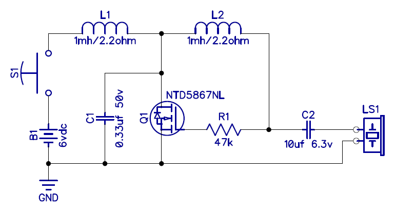
Given the low power consumption with a 0.6ohm L1 inductor in series only with Q1... it MUST be that Q1 is not being switched-on for much of the cycle. You're likely aware that I have removed any zener and am, instead, just using the RC filter composed of a 47k resistor and the MOSFET's inherent rather high gate capacitance. You should scope the MOSFET's drain (the L1/L2 junction) to see how much of the time it's held at ground by the MOSFET. Mine is low (Q1 saturated) 73% of the time and released only 27% of the time. And I have seen that this DIRECTLY effects both the power consumption and the output volume of the circuit.
You might also try moving the feedback resistor to the L2 side of C2. I have just done that in my latest (v2.0.4) reference design. I was playing with REDUCING the duty-cycle by putting a higher-valued resistor where the zener used to be... to create a voltage divider and tend to pull the gate down. What ALSO happened was truly fascinating!... C2 got charged up by the new current path and the oscillator shut down after a few seconds. <g>
For that reason, I have moved the feedback to the high-end of C2... so that we're not dependent upon C2 not acquiring a charge for the system to operate.
You might try adding some discrete very low value series resistors if you have some in the ohm range. :)
It might be worth a play. I happen to have a reel of nichrome wire which I use for arbitrary, hi-watt, lo value resistors (e.g. mirror demisters and PA dummy loads!). Maybe we can get some understanding of the role of the resistances that way?
Indeed.
/Steve.
adrian.p...@gmail.com
2012年12月16日 16:46:232012/12/16
收件人 portable-so...@googlegroups.com、steve....@gmail.com、adrian.p...@gmail.com
On Sunday, December 16, 2012 9:09:12 PM UTC, Steve Gibson wrote:
Nope. I have a very juicy adjustable lab power supply. I watch its current meter like a hawk as it can deliver amps and has done once or twice when things go wrong! The non-digital version consumes 0.16A at 6V.I may be getting a bit confused among the various people who are playing with the circuit. But I think you mentioned that you weren't using a triggerable storage scope, so you were using a multimeter to measure the RMS output voltage?... but you were unsure how it might be responding to a 15khz signal?
Steve,
The current measuring meter is the one integrated with the bench power supply. I'll check out the Fluke 79 frequency response shortly. It won't be far out. I have a 'toy' handheld LCD scope which is good enough for seeing waveform shapes.
Given the low power consumption with a 0.6ohm L1 inductor in series only with Q1... it MUST be that Q1 is not being switched-on for much of the cycle. You're likely aware that I have removed any zener and am, instead, just using the RC filter composed of a 47k resistor and the MOSFET's inherent rather high gate capacitance...
Aha. I did see that circuit and wondered whether it was going to break the MOSFET. I have spares, so I've tried it. WOW! We are doing nearly 0.5A (PSU meter) and 30VAC rms (Fluke) @ 14.5kHz (Fluke). However, the tweeter isn't liking it much. I've not run it for long at these powers.
Anyway, the main thing is that our circuits are converging in performance, despite the lowR inductors. We may not need to worry about that issue, which would be good since this isn't something that is very certain when sourcing them. However, I don't regret getting switching PSU grade ones!
You might also try moving the feedback resistor to the L2 side of C2...
Umm. I've just realised that that is where it was all the time! As we've discussed, it is only a few volts different. So, essentially all I've done is remove the Zener to achieve this rather startling change in performance. Maybe that's the way to trim the output to something the tweeter is happier with?
A bit puzzling just for me at the moment, but progress ;-)
Adrian/
Steve Gibson
2012年12月16日 17:08:042012/12/16
收件人 portable-so...@googlegroups.com、steve....@gmail.com、adrian.p...@gmail.com
Adrian...
Aha. I did see that circuit and wondered whether it was going to break the MOSFET. I have spares, so I've tried it. WOW! We are doing nearly 0.5A (PSU meter) and 30VAC rms (Fluke) @ 14.5kHz (Fluke). However, the tweeter isn't liking it much. I've not run it for long at these powers.
Nice! You might try reducing the supply voltage. 4.5vdc still works nicely.
And 30vac rms is about 90 vac p-p assuming a pure sine wave!!
So NOW we're seeing the effect of your low-R inductors!!
Anyway, the main thing is that our circuits are converging in performance, despite the lowR inductors. We may not need to worry about that issue, which would be good since this isn't something that is very certain when sourcing them. However, I don't regret getting switching PSU grade ones!
Right. The trouble you'll have will only be generating TOO MUCH power for the poor tweeter. You might find that a 3-cell, 4.5vdc solution makes more sense.
You might also try moving the feedback resistor to the L2 side of C2...
Umm. I've just realised that that is where it was all the time! As we've discussed, it is only a few volts different. So, essentially all I've done is remove the Zener to achieve this rather startling change in performance. Maybe that's the way to trim the output to something the tweeter is happier with?
Actually... I believe you'll find that replacing where the Zener was, with 100k pot in series with a 15kohm resister... yields a wonderful "volume control", and also a power control -- it allows you to bring the output voltage down by smoothly reducing Q1's duty-cycle, thus ALSO reducing power consumption. :) (In other words, a resistance of 15k to 115k from MOSFET gate to ground.)
I have also experimentally confirmed the effect of the power MOSFET's gate capacitance (the RC filter I posited) by playing with a non-power MOSFET having a very low gate capacitance. The gate phase now very closely tracks the L2 output phase (due to less RC-delay) and results in a purer but much reduced output volume. Also... being a non-power MOSFET, this transistor's Ron is several ohms, so it doesn't compete well with L1 which it's essentially shorting across the supply.
A bit puzzling just for me at the moment, but progress ;-)
Indeed. :) What fun!!
/Steve.
adrian.p...@gmail.com
2012年12月16日 17:17:172012/12/16
收件人 portable-so...@googlegroups.com、steve....@gmail.com、adrian.p...@gmail.com
Steve,
Just as a an addendum, I have unwrapped my L2 to try and get the frequency higher and with success. Note I have just unwrapped i.e. the internal R is the same - I've not cut the wire off (I might want to put it back!). Frequency is now 16kHz and the tweeter seems a little happier up there.
Interestingly, the drive is up too. Nearly 30VAC and 0.6A (same measuring instruments).
OK on batteries but certainly better on the PSU. I'll see what reduced volts does.
Adrian/
Steve Gibson
2012年12月16日 17:28:042012/12/16
收件人 portable-so...@googlegroups.com、steve....@gmail.com、adrian.p...@gmail.com
Just as a an addendum, I have unwrapped my L2 to try and get the frequency higher and with success. Note I have just unwrapped i.e. the internal R is the same - I've not cut the wire off (I might want to put it back!). Frequency is now 16kHz and the tweeter seems a little happier up there.
Interestingly, the drive is up too. Nearly 30VAC and 0.6A (same measuring instruments).
OK on batteries but certainly better on the PSU. I'll see what reduced volts does.
Nice!
I have a potential improvement: Connect the Q1 gate to ground with a 0.01uf ceramic cap and reduce the series resister to 10.
This results in a LOVELY sine-wave drive of Q1 and makes the circuit much less dependent upon Q1's gate capacitance, which is about 1/25th of the value of the new gate capacitor. I am getting a higher and "purer" output now. I might want to reduce R1 below 10k, though, since the gate drive ought to be higher. Just something for you to play with if you're curious. :)
/Steve.
adrian.p...@gmail.com
2012年12月16日 17:44:092012/12/16
收件人 portable-so...@googlegroups.com、steve....@gmail.com、adrian.p...@gmail.com
On Sunday, December 16, 2012 10:28:04 PM UTC, Steve Gibson wrote:
I have a potential improvement: Connect the Q1 gate to ground with a 0.01uf ceramic cap and reduce the series resister to 10.
Steve,
I presume you meant 10k. I think it is an improvement, but more important is reducing the volts, as you suggested. I think the real problem is the tweeter quality.
I can't run the thing for long anyway as it is LOUD!
I've wrapped the inductor up partially again. I was having problems with the circuit starting (and therefore likely to fry the MOSFET!).
Over here it is getting nearly time for sleep. I'll drop in tomorrow. I plan to return the tweeter to RS and it may be a few days before I get another :-(
Adrian/
Steve Gibson
2012年12月16日 18:22:022012/12/16
收件人 portable-so...@googlegroups.com、steve....@gmail.com、adrian.p...@gmail.com
Adrian...
I have a potential improvement: Connect the Q1 gate to ground with a 0.01uf ceramic cap and reduce the series resister to 10.
Steve,
I presume you meant 10k.
Whoops! Yes, right. :)
I think it is an improvement, but more important is reducing the volts, as you suggested. I think the real problem is the tweeter quality.
I can't run the thing for long anyway as it is LOUD!
As it was designed to be! <<grin>> But you're right... the $2 tweeters CAN be good, but my guess is that their "quality control" is virtually non-existent. But... using a $2 tweeter, if possible, in a production device would be a lot more economical than an $18 dollar device.
It's beginning to look like I'm going to be building 100 of these for wide spread beta testing. I'm going to see how good a price I can get from suppliers of the better "Made in the Philippines" units. But I might well go with the "Goldwood GT-1005" and use those 100 non-paying testers to also test the tweeter quality. :)
I've wrapped the inductor up partially again. I was having problems with the circuit starting (and therefore likely to fry the MOSFET!).
Over here it is getting nearly time for sleep. I'll drop in tomorrow. I plan to return the tweeter to RS and it may be a few days before I get another :-(
Adrian/
I'd been nice to have someone else experiencing the LOUDNESS of the result. I think I'm zeroing in on the design. I know pretty much everything about it now. As soon as the next round of components arrive mid-week I should be able to make the final tweaks to the design. :)
/Steve.
billmcf
2012年12月17日 14:42:562012/12/17
收件人 portable-so...@googlegroups.com
On Friday, December 14, 2012 8:19:59 PM UTC-8, Steve Gibson wrote:
Bill...
Steve,
I think this would work if you moved the 47k resistor to the other side of the 10uF DC blocking cap (as you have done in your latest v2.0.4 design).
If you want to keep the switch where it is, an RC snubber across the switch might be useful to limit arcing / contact wear when the button is released.
Steve Gibson
2012年12月17日 15:00:512012/12/17
收件人 portable-so...@googlegroups.com
Hi Bill!
( And welcome back from a busy (here) weekend! :)
Well, one solution would be to use a SPDT pushbutton, with the button's common attached to the MOSFET's gate, the normally closed (NC) connection to ground -- thus grounding the gate to the source and shutting it off firmly, and the normally open (NO) connection to the 47k ohm series resistor. But SPDT pushbuttons are more expensive and more to wire up than SPST. So probably the best answer, at the trivial cost of one more resistor, would be to tie a high-value resistor from the gate to ground, and use any inexpensive SPST pushbutton to briefly connect the gate to the 47k feedback resistor.
By the way... in case you didn't catch it amid and weekend's activity... I assumed, then experimentally verified, that the reason this super-simple-system operates as well as it does... is due to the opportunistic capacitance of the power MOSFET's gate coupled with the relatively high value of the feedback resistor. I have since verified that it doesn't work well with a low-gate-capacitance MOSFET, but that by deliberately creating an RC feedback filter outside of the MOSFET a strong oscillator can be created again.
So we have a rock solid and increasingly well-understood design! :)
(And this discussion just gate me another thought! <<grin>> )
/Steve.
( And welcome back from a busy (here) weekend! :)
I think this would work if you moved the 47k resistor to the other side of the 10uF DC blocking cap (as you have done in your latest v2.0.4 design).If you want to keep the switch where it is, an RC snubber across the switch might be useful to limit arcing / contact wear when the button is released.
Well, one solution would be to use a SPDT pushbutton, with the button's common attached to the MOSFET's gate, the normally closed (NC) connection to ground -- thus grounding the gate to the source and shutting it off firmly, and the normally open (NO) connection to the 47k ohm series resistor. But SPDT pushbuttons are more expensive and more to wire up than SPST. So probably the best answer, at the trivial cost of one more resistor, would be to tie a high-value resistor from the gate to ground, and use any inexpensive SPST pushbutton to briefly connect the gate to the 47k feedback resistor.
By the way... in case you didn't catch it amid and weekend's activity... I assumed, then experimentally verified, that the reason this super-simple-system operates as well as it does... is due to the opportunistic capacitance of the power MOSFET's gate coupled with the relatively high value of the feedback resistor. I have since verified that it doesn't work well with a low-gate-capacitance MOSFET, but that by deliberately creating an RC feedback filter outside of the MOSFET a strong oscillator can be created again.
So we have a rock solid and increasingly well-understood design! :)
(And this discussion just gate me another thought! <<grin>> )
/Steve.

Kindanyume
2012年12月17日 15:10:372012/12/17
收件人 portable-so...@googlegroups.com
On Mon, Dec 17, 2012 at 3:00 PM, Steve Gibson <steve....@gmail.com> wrote:
> (And this discussion just gate me another thought! <<grin>> )
>
> /Steve.
Once again yet more proof that SG is actually the evil overlord trying
> (And this discussion just gate me another thought! <<grin>> )
>
> /Steve.
to hide his "evil grin" as a simple <<grin>> :P

Jon Katayanagi
2012年12月17日 17:31:452012/12/17
收件人 portable-so...@googlegroups.com、portable-so...@googlegroups.com
After all the test, maybe you can record and develop an iOS app
for testing. If it works as just a sound bite on an iPhone, building a kit will not be needed for close range.
JonK
Sent from my iPhone
for testing. If it works as just a sound bite on an iPhone, building a kit will not be needed for close range.
JonK
Sent from my iPhone
Kindanyume
2012年12月17日 17:37:132012/12/17
收件人 portable-so...@googlegroups.com
Sorry but... EWWWWWWWWWWWWWW
Android FTW :)
(sorry I can't stand IOS products.. despite being in IT for decades)
Android FTW :)
(sorry I can't stand IOS products.. despite being in IT for decades)
Steve Gibson
2012年12月17日 18:02:412012/12/17
收件人 portable-so...@googlegroups.com
Jon...
This project is ALL ABOUT generating the loudest, high-intensity, high-frequency, directed sound beam possible with a simple low-cost design.
It's possible to make an "eeeeeeeeeeeeeeeee!" sound with the iPhone or iPad... but that'll just make a dog bark MORE rather than have it reconsidering the wisdom of standing its ground.
/Steve.

James Moede
2012年12月17日 18:43:332012/12/17
收件人 portable-so...@googlegroups.com
Will you be producing a schematic with Digi-Key parts list (similar to the micro-controller version)? I would like to breadboard this to try it - it looks much easier than the other version.
James Moede
On Friday, December 14, 2012 3:16:23 PM UTC-6, Steve Gibson wrote:
James Moede
On Friday, December 14, 2012 3:16:23 PM UTC-6, Steve Gibson wrote:
Everyone...THIS WORKS WONDERFULLY!!
You may notice that there's something conspicuously missing... the micro controller!Over in the "Auto Tune" thread, Bill McFadden and I have been enjoying a dialog about the possibility of getting the circuit to oscillate all by itself. He ran a simulation that said it would. The more I thought about it, the more obvious it was that it would do SOMETHING, since the MOSFET is wired up as a high-gain inverter, and it's driving a tuned circuit that will have a strong voltage-phase delay. So I simply took the tuned output and coupled it back to the MOSFE's input with a series resistor and zener clamp to protect the MOSFET's somewhat delicate gate.It oscillates like a bat of of hell!!It produces a MORE PURE HIGHER VOLTAGE sine wave than when the system was being driven by the processor. And... it (currently) PREFERS oscillating at about 14.2 khz!!Furthermore, exactly as would be predicted, as the piezo element in the tweeter heats up and changes its reactance, the whole system adjusts its frequency smoothly and automatically to remain in the "sweet spot" of the current components.It is a WIN WIN WIN!! And this result demonstrates the power of open collaboration among smart people. :)A few notes:1. You may note that the resistance of L1 is now about twice that of L2. That's a change I silently made a few days ago when I was thinking about how much time the MOSFET is spending "ON". This modification is non-critical, but it will reduce WASTED power in L1 and yield a longer battery life... likely without any reduction in output power. (I wasn't keeping this a secret, I just wanted to put as much possible into the next design update.) This is new L1 is DigiKey Part No. 445-6494-1-ND.2. The values of the two new components -- the 10volt Zener and the 47k resistor -- are both non-critical. They are both there only to protect the MOSFET's gate. The zener needs to be above the MOSFET's full turn-on gate-drain threshold voltage, but also safely below its gate breakdown voltage. So anything between 3 and 9 volts. (I should be using a lower voltage zener and I will in the final design... I just didn't have one handy.) The resistor is there to limit the current through the zener -- both when it's clamping the gate at its positive "zenering" voltage, and also when it's clamping the gate in its forward biased mode at a low negative voltage.This all JUST happened... so you would be best advised to waitthrough the weekend so that I can settle down and get it tunedfor minimum power consumption and maximum output.And if you're wondering about the role of, and need for the micro... I do still plan to use it in my design to control the "blast duration" and "blast radius" (volume) of the device. But if you want a simple push-to-blast solution... the micro is no longer needed!One further note: Using the switch to switch the battery COULD now create some arcing in the switch since you'll have both high amperage and often high voltage there. So what I once said about the switch being "anything" doesn't apply in this revised usage./Steve.

Kyle Smith
2012年12月17日 20:49:372012/12/17
收件人 portable-so...@googlegroups.com
Hi Steve,
Actually it was first on my iPad that I discovered that my own dogs were responsive to 18KHz. There are several existing apps that use a simple threshold SPL to activate the stimulus sound.
However, it's not loud enough for full house coverage, but does work in a small room. At any rate, I have never observed an increase in barking upon the emission of an 18 KHz sine wave, quite the opposite has been my experience. My dogs respond by alerting with their ears, moving them about as if they were attempting to localize the sound. It seems initially that they stopped barking because they were diverted by this new sound in their environment. When I switched to using my powered bookshelf monitors, and restricted the use of the stimulus to only thoughts occasions when the dogs were barking as a pack, with the volume set so that it was just below the threshold of hearing any audible distortion, they have come to take it as a command to stop yapping, and generally stop immediately. Now this is all being done indoors, however, I think it dispels the notion that a moderate volume high frequency pure sine wave would cause a dog to become more aggressive at barking.
Of course, what I've said cannot be thought to apply to a dog who is not just barking, but actually attacking someone. However, my experience has been that dogs who attack humans do not typically bark while attacking. And certainly not a dog who has been taught to attack humans, by law enforcement or the DOD. But those dogs would not likely be deterred by any acoustic stimulus, because of their rigorous training, which includes being exposed to live gun fire during the course of carrying out a command.
I'm not opposed to the goal of achieving the biggest acoustic bang from a few AA batteries, I rather enjoy the engineering issues which have come up with the latest version (which will likely be old news by the time this is read.) Nothing so exciting as being witness to the rapid changes in direction that occur when a project is being designed de novo, in plain view of a kibitzing public. It's the magic of collaboration, as well as a burden to those accustomed to crafting code silently, in a introverted manner, including complete social isolation, which is my more normal affect when I am coding. But then there is no code involved any longer. It has come to be an analog hardware project.
Best of luck in your effort. I will certainly attempt to duplicate the circuit once it is released as a draft standard.
Best wishes,
--
Kyle Smith AG2F
James Moede
2012年12月17日 20:58:142012/12/17
收件人 portable-so...@googlegroups.com
I found it on your "R&D Progress Log / Friday Afternoon Update" group. I am ordering the parts and will keep you posted on my results.
Steve Gibson
2012年12月17日 22:24:082012/12/17
收件人 portable-so...@googlegroups.com
Thanks Kyle! :)
/Steve.
/Steve.
Kindanyume
2012年12月18日 13:46:032012/12/18
收件人 portable-so...@googlegroups.com
Just a note again.. for some in Canada.. hopefully close to me
(Hamilton) I will import a bunch of parts in one batch to help
eliminate added costs.. and then they can be distrib'd locally and/or
snail mail to avoid high shipping fees etc. Those that want such..
lmk.. so I can get an idea of what I'd be ordering in advance etc etc.
(Hamilton) I will import a bunch of parts in one batch to help
eliminate added costs.. and then they can be distrib'd locally and/or
snail mail to avoid high shipping fees etc. Those that want such..
lmk.. so I can get an idea of what I'd be ordering in advance etc etc.

bob.be...@gmail.com
2012年12月18日 14:03:562012/12/18
收件人 portable-so...@googlegroups.com
Will this drive two tweeters or just one? If two, should they be wired in parallel or in series?
Steve Gibson
2012年12月18日 15:27:072012/12/18
收件人 portable-so...@googlegroups.com、bob.be...@gmail.com
Bob...
Whatever you do, be SURE to pay attention to the banner at the top of the main group page which tells you to go to the BOTTOM of the "R&D Progress Log / Friday Afternoon Update" topic in order to get the latest design news and updates.
Will this drive two tweeters or just one? If two, should they be wired in parallel or in series?
Part of the cleverness of this design (I am quite proud of it and I think it's quite a nice bit of engineering) is it's "high utilization" of very few components which allows us to do a lot with very little. In the case of the tweeter, its inherent piezoelectric capacitance forms a critical part of the circuit, oscillating in an LC arrangement to produce a sine wave which is the optimal wave shape for exciting a piezoelectric transducer.
But that means that the CAPACITIVE VALUE of the tweeter is half of what sets the system's frequency. The other half is the inductive value of the L2 inductor. When two identical capacitors are connected in series the equivalent capacitance is HALF of their individual values. When two identical capacitors are connected in parallel the equivalent capacitance is TWICE their individual values.
Therefore... with any given value for the L2 inductor, two tweeters connected in series would have half the capacitance and oscillate at TWICE the frequency as would one. And two tweeters in parallel would oscillate at HALF the frequency as would one. Since the tweeters in series would divide the output power between themselves I would choose to run these in parallel... and our growing experience is showing that this little amplifier is easily powerful enough to drive multiple tweeters. But the value of L2 would need to be cut in half, to 470uH, to keep the frequency high.
Frankly... the little oscillator is SO lightweight and small, that I'd give each tweeter its own. This has the significant advantage of have the oscillators unlocked and sliding (beating) in and out of phase with each other. It would likely be unimaginable.
/Steve.

w9arg...@gmail.com
2012年12月20日 20:50:442012/12/20
收件人 portable-so...@googlegroups.com
Hi Peeps,
Love the project, can.t wait to see parts list, to build one up.
ok what if you had two LC circuits that can be tuned to two different hz. Then with two triggers {switches} you can change up the hz.
This could be helpful for the trainers, who may want to send differ msg's to the dog/pet. Or to drive the dog crazy, with a higher distance setting.
Stay safe this week and can't wait for the xmas break show on SN
Jeff from chicago
--30--
On Friday, December 14, 2012 3:16:23 PM UTC-6, Steve Gibson wrote:
Everyone...THIS WORKS WONDERFULLY!!
You may notice that there's something conspicuously missing... the micro controller!
回复全部
回复作者
转发
0 个新帖子