Orange filter

Chris Fastie
Joe,
Using an orange filter in a single-camera infrared plant analysis system seems like a good idea. I think you have described very well how this would work and how it would differ from cameras with blue or red filters. As you say, an orange filter instead of red will allow green light to be captured in the green channel (along with NIR), whereas a red filter blocks most green and captures mostly NIR in the green channel. You also mention that the blue channel will capture “mostly NIR.” Unlike the red filter, an orange filter will probably allow some green and a little blue into the blue channel (in addition to NIR), so it will not provide as pure an NIR image. This is the compromise -- to capture information about green light (mixed with NIR), you sacrifice the clean NIR image that is possible with a red filter.
I am not sure how much an advantage it will be to have a channel with green and NIR mixed. You will still be missing any blue information, so a true color image is not possible. It is possible that the false color infrared (CIR) images produced might be much more similar to legacy color infrared images than those produced with a red filter. With red-filtered images, I have made lots of CIR images (NRG) by displaying the green channel as blue, but it is really just another NIR channel being displayed as blue. An orange filter would allow some actual green to be displayed in that channel. On the other hand, the NIR channel (blue) will be more contaminated than when using a red filter.
Capturing photos with an orange filter in order to produce NDVI directly from the photo will probably require a custom white balance, just as with red or blue filters. Some experimentation will be required to find that setting. Also, a camera capable of custom white balance will be needed. Another approach is to calibrate the NDVI results by photographing targets of known red and NIR reflectance as Ned Horning has been doing.
I like the orange filter idea so I just ordered a Wratten 15 filter on ebay ($10 for four 3-inch filters including 25A and 15). There is a nice new Wratten 15 available here (http://www.ebay.com/itm/Kodak-No-15-1495548-3-Wratten-Gel-Filter-/191474169507?pt=Camera_Filters&hash=item2c94bff6a3).
As far as I can tell, some of the Tetracam ADC cameras work exactly as described above by using a consumer sensor, no IR block filter, and a yellow filter. Below is a figure from their ADC User’s Guide from a few years ago (http://www.tetracam.com/PDFs/ADC%20Users%20Guide%20V2.3.pdf) . This shows a sensor with three Bayer-filtered color channels, no IR blocking filter, and a yellow filter to block everything but NIR from the blue channel. This is what you are proposing.

Tetracam also uses other approaches. Their MCA systems use multiple cameras (one for each band) and have the potential to provide results similar to the narrower band Thematic Mapper approach. Their description of some of the ADC cameras suggests they might use some other approach to single camera NDVI systems, but they don’t provide enough information to know for sure. So it might be that the Tetracam ADC Micro is very similar to a point and shoot with a yellow filter (except with 25% of the resolution and two orders of magnitude more expensive). However, the marketing language suggests that they might use a sensor with a custom color filter array (instead of a Bayer CFA) that passes Red, Green, and NIR (instead of R, G, and B). That would be awesome, but because they obfuscate, I suspect that they have not taken that more expensive approach. Certainly some of the Tetracam ADC cameras are just wildly overpriced very low resolution cameras with standard Bayer filtered sensors. So it seems to be quite misleading to refer to these as having “Green, Red and NIR sensitivity with bands approximately equal to TM2, TM3 and TM4” as their web page does.
The protocol for producing plant analysis images from Tetracam ADC photos involves taking separate photos of calibration targets and post processing all other photos. A primary goal is to deal with the unknown mix of NIR and visible light in each channel. Apparently the calibration procedure involves determining the proportion of NIR and visible light in each channel and then adjusting each channel to get a final RGNir image. I am not sure exactly how this works, but they apparently do it with only one calibration target. This suggests they are not using regression as Ned Horning does which would require multiple targets of varying reflectance. The User’s Guide says “The ratio of red/NIR or green/NIR is then applied as an offset to the calculation of the various vegetation indices.”
So how does this work? We know that for each pixel, the red channel is an unknown mix of red and NIR light. We can know the actual ratio of red/NIR only for the pixels of the calibration target. So for the target pixels the difference between the known target ratio and the captured ratio could be used to adjust the ratio for all pixels. That means that all plant pixels with a brightness of, say, 50% (DN = 127) in the red channel are assumed to have the same reflectance of red. But we know that plant health affects the ratio of red/NIR. In fact, that is exactly what we are trying to measure. So how can we assume that all of the plant pixels with 50% brightness in the red channel (a channel with mixed red and NIR data) have the same reflectance of red?
I guess we have additional information in the blue channel. Just as above, for the calibration target pixels, we know how much of the brightness in the blue channel is NIR. So we get separate estimates of the reflectance of red (from the red channel) and NIR (from the blue channel ). We can then compare that red/NIR ratio to the known ratio of red/NIR of the target. Then an additional adjustment can be made for each non-target pixel to estimate the red/NIR ratio.
I am not sure what the Tetracam protocol is or what their PixelWrench software does, but it does not seem to implement a two stage process as described above.
If you could make photos with perfectly clean channels of NIR , red, and green data, the data still has to be calibrated because consumer sensors are not equally sensitive to R, G, B, and NIR. Even two-camera systems with a pure NIR camera and a pure visible camera don’t tell you the real red/NIR ratio because 1) consumer sensors seem to be much less sensitive to NIR than to red, and 2) the two cameras might not have used the same exposure settings. In addition to this problem, one-camera systems generally have visible and NIR light mixed together in each channel. So further processing is required to estimate what the mixture is. This seems to be a nastier problem, and one to be avoided if possible. Using a two-camera system is a good way to avoid this problem.
Kites, balloons, and UAVs are quite capable of lifting two (or more) cameras, and that is probably the best approach. UAVs that cost only $80 probably cannot lift two very big cameras, so if you are limited by that budget it might be worth the sacrifice in data quality to fly a single camera. On the other hand, the technology of UAVs and cameras is advancing fast enough that waiting could be a solution. Maybe in a couple of years a $100 UAV will be able to fly two (or four) cameras and collect the data we really need.
Chris
------------------------------------------------------
Message from Joe Sommer on 01/07/2015
Chris,
I have a question at the bottom of this rather long note. I hope that the next sentence does not offend a kite guy.
We are planning to fly some really cheap quadcopters ($80) to try quick-and-dirty NDVI measurements. They do not have internal IR blocking filters in their cameras.
We also have a Tetracam ADC Micro for standard NDVI and will use it as the “gold standard” to calibrate the cheap cameras. Tetracam provides green, red and NIR comparable to Landsat Thematic Mapper TM2, TM3 and TM4 bands.
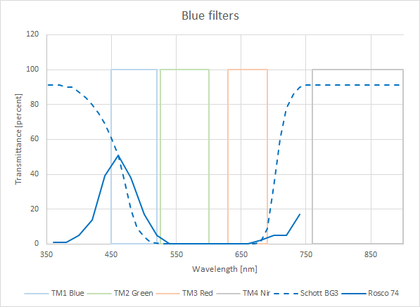
For a camera with no IR block and a blue filter per attached “blue filters.png”, red and green light will be blocked. The camera will record mostly NIR on the R and G channels and will record NIR plus blue light on the B channel. Some weighted combination of R and G channels can then be used for NIR in NDVI computations and some weighted combination of the B channel can be substituted for red (loosely based on the dual absorption peaks of chlorophyll). This approach can be affected by atmospheric degradation of blue light reflected from plants.
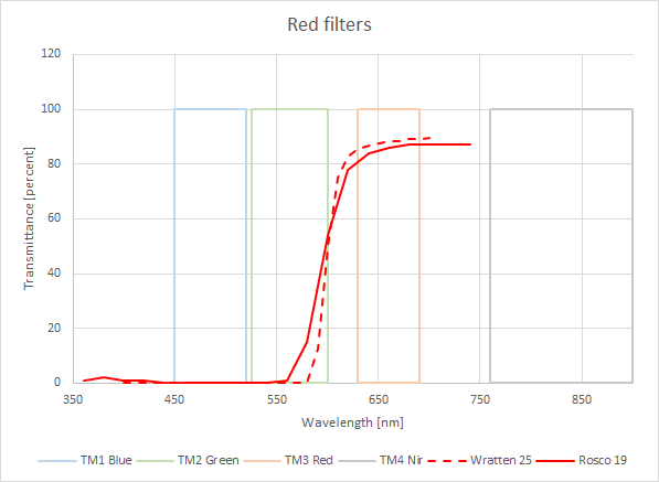
For a camera with no IR block and a red filter per attached “red filters.png”, blue and green light will be blocked. The camera will record mostly NIR on the B and G channels and will record NIR plus red light on the R channel. Some weighted combination of B and G channels can then be used for NIR in NDVI computations and some weighted combination of the R channel can be used for red.
The difficulty is to calibrate weighting factors to combine RGB channels as described above. Our preliminary testing indicates that unblocked cameras with red filters match Tetracam NDVI better than with blue filters.
Unfortunately, both approaches block green light. However green is available from Tetracam for qualitative visualization.
Finally, here is my question …
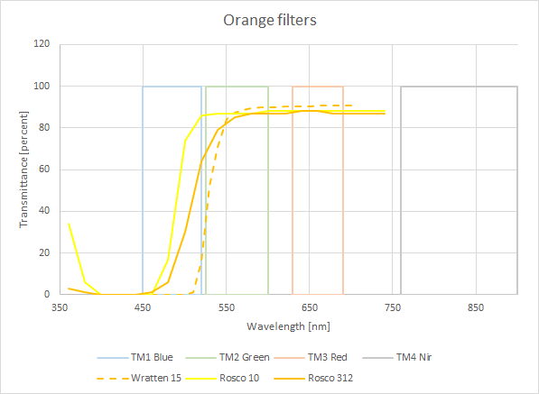
Have you seen any attempts to use orange filters per attached “orange filters.png”. They would only block blue light. The camera would record mostly NIR on the B channel, would record NIR plus green light on the G channel and would record NIR plus red light on the R channel. Some weighted combination of the B channel can then be used for NIR in NDVI computations and some weighted combination of the R channel can be used for red. Some weighted combination of the G channel is now available to provide green and assist with qualitative inspection.
I would appreciate your thoughts.
Thanks in advance,
Joe Sommer
*******************************************************************
H.J. Sommer III, Ph.D., Professor, Fellow ASME
Department of Mechanical and Nuclear Engineering
The Pennsylvania State University

Joe Sommer
On Thursday, January 8, 2015 12:15:51 PM UTC-5, Chris Fastie wrote:
I like the orange filter idea so I just ordered a Wratten 15 filter on ebay ($10 for four 3-inch filters including 25A and 15).
Thanks for your extensive reply.
We are still working in the lab to prepare for spring (currently
10 deg F outdoors). Our primary application will be turfgrass.
We have several systems that we plan to use.
a) hand-held close-range NDVI sensor
b) Tetracam ADC Micro
c) DJI Phantom Vision Plus quadcopter (internal camera, no IR block filter)
d) Hubsan X4 H107C-HD quadcopter (internal camera, no IR block filter)
We will perform correlation calibration of the Tetracam
using reflective targets and hand-held NDVI measurements.
After that, we will fly the Phantom and Hubsan with red,
blue and orange filters. However they have very little control
over white balance and may not be very effective.
We will post occasionally to this list.
Best wishes,
Joe Sommer
P.S. Please forgive my odd avatar photo. It is related
to one of my other Google groups, R/C Tank Combat.
Chris Fastie
Joe Sommer
On Saturday, January 17, 2015 at 10:35:53 AM UTC-5, Chris Fastie wrote:
It boggles the mind to think of how many photos of grass you will have to look at.
<<< snip >>>
I tried a Wratten 15 filter and compared it to Wratten 25A. They make similar NDVI images but the CIR images are distinctly different. More here.
Chris,
Thank you for capturing and analyzing images using the Wratten 15 and Wratten 25A filters.
This corroborates our preliminary results from small potted trees that we drag outdoors on
warmer sunnier days (recently few and far between). Qualitatively, red and orange filter tests
produce very similar NDVI results.
Hopefully, our camera calibration tests on turfgrass this spring and summer will be able
to tell us if red and orange filter results are statistically different or the same. If they
are statistically the same, we will use orange because it provides the additional green
channel for direct manual visualization.
On another issue that was recently posted under Understanding NDVI scale (green to red) ,
our turfgrass people want to use a much simpler NDVI colorbar. They want a simple linear
map with NDVI = +1 as bright green and NDVI = -1 as bright red with no blue, white, grey,
black etc. We do not plan to use CIR images. Because we will calibrate weighting
coefficients and will not depend on white balance, we should be able to provide histogram
stretching for this mapping.
Best wishes,
Joe
Chris Fastie

David Brooks
Could you provide the algorithm for producing these false color images on the infragram site? This is processed from a Mobius point-and-shoot camera (red filter) image. I assume the processing uses the red and blue channels, and ignores the green channel?
To be more specific, if I have software that looks at the RGB values for each pixel in a near-IR image from this camera, converted to a .bmp file, how would I alter the values to produce this false color image? This looks like perhaps you calculate a grayscale NDVI value and then "colorize" some of the pixels based on those values. Perhaps what I'm looking for is a text version of your NDVI_VGYRM.lut file.
Although this processing may not look as "pretty" as other representations, I find it more useful as an image for conveying NDVI information.
BTW, I have written software in C or PHP that will do this kind of processing on .bmp files. If anybody is interested, I would be glad to provide the code -- very much an "as is" work in process, but it does show how to read and process .bmp files pixel by pixel.
In any event, Chris, thanks for your input on these matters!
--
Post to this group at plots-i...@googlegroups.com
Public Lab mailing lists (http://publiclab.org/lists) are great for discussion, but to get attribution, open source your work, and make it easy for others to find and cite your contributions, please publish your work at http://publiclab.org
---
You received this message because you are subscribed to the Google Groups "plots-infrared" group.
To unsubscribe from this group and stop receiving emails from it, send an email to plots-infrare...@googlegroups.com.
--
David R. Brooks, PhD, President
Institute for Earth Science Research and Education
2686 Overhill Drive
Worcester (Eagleville), PA 19403  USA

voice: 610-584-5619/8014
FAX (by request only): 610-584-5619
e-mail: broo...@InstESRE.org
Skype ID: davidrobertbrooks

web: www.InstESRE.org (IESRE home page and all other related work)

Quality science education requires that teachers and students be engaged in doing real science.


"Human history becomes more and more a race beween education and catastrophe." -- H. G. Wells (The Outline of History, 1920)
Mathew Lippincott
https://github.com/nedhorning/PhotoMonitoringPlugin
and here's the Infragram Javascript code:
https://github.com/publiclab/infragram-js
Chris Fastie
David Brooks
Thanks! I assume that in this table the "Index" values represent NDVI values as you have defined them below, from -1 to +1 scaled over integer values 0-255. Based on your assumption that any NDVI value less than 0.1 can't be vegetation and will be represented as grayscale, (1.1/2)*255=140. In your scaling, index value 137 is the first value assigned a color (slightly bluish) -- close enough!
For anyone wishing to try generating false-color NDVI images themselves from a near-IR image, I believe this exchange has provided all the insight needed to get started, assuming you can process images one pixel at a time. I know FIJI, for example, can do this kind of thing automatically, but for me, the most direct and transparent approach is to use .bmp images because of their straightforward file structure.
--
Post to this group at plots-i...@googlegroups.com
Public Lab mailing lists (http://publiclab.org/lists) are great for discussion, but to get attribution, open source your work, and make it easy for others to find and cite your contributions, please publish your work at http://publiclab.org
---
You received this message because you are subscribed to the Google Groups "plots-infrared" group.
To unsubscribe from this group and stop receiving emails from it, send an email to plots-infrare...@googlegroups.com.
Chris Fastie
Chris Fastie
Image/Color/Edit LUTopens the current LUT in an editor. Highlight one or more of the 256 colored squares and you can change those blocks to any color or to a gradient between any two colors. Then save.
