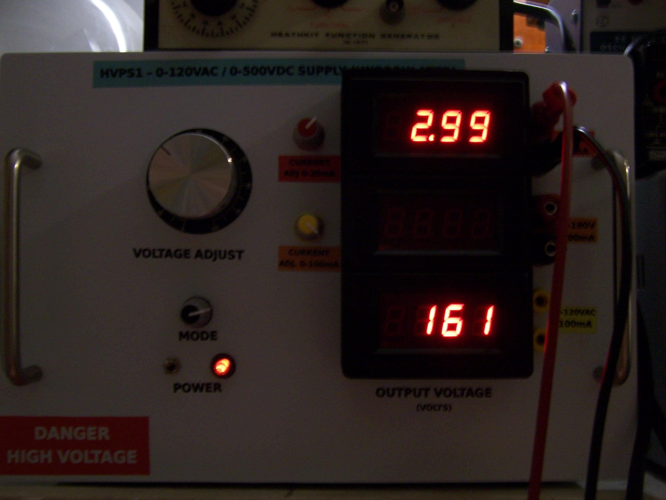
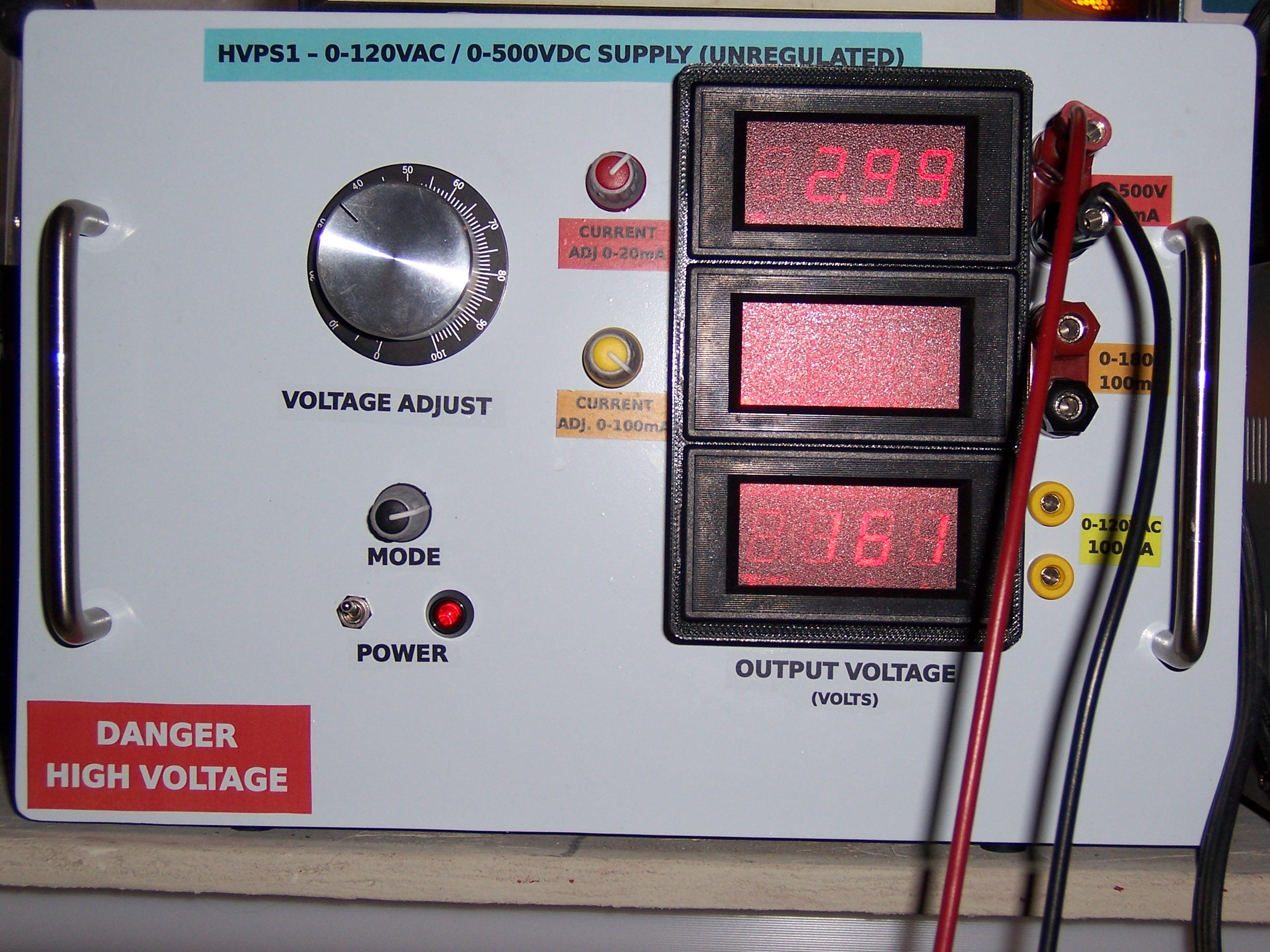
Nixie bench supply

gregebert

Dekatron42

GeckospotNixie
Gregebert
Just sent you another private reply about the PCBs.
Don't know if you getting them or not.
Google has no way for me to find out if I even sent a private reply.

Tidak Ada
Please can I get the PCB artwork too?
I think the design is interesting enough to give some explanation about the it to the group.
Thanks,
eric
--
You received this message because you are subscribed to the Google Groups "neonixie-l" group.
To unsubscribe from this group and stop receiving emails from it, send an email to neonixie-l+...@googlegroups.com.
To post to this group, send email to neoni...@googlegroups.com.
To view this discussion on the web, visit https://groups.google.com/d/msgid/neonixie-l/f6abd12a-256f-425e-a6eb-1f7641fb9d02%40googlegroups.com.
For more options, visit https://groups.google.com/d/optout.
gregebert
GeckospotNixie
Thanks for the update!
And thank you for your time and giving back to the community.
GeckospotNixie
Tidak Ada
Hi ,
Does this mean I am in the running for a board set? (I hope so).
Extra costs for shipment outside of the US will be paid!
eric
--
You received this message because you are subscribed to the Google Groups "neonixie-l" group.
To unsubscribe from this group and stop receiving emails from it, send an email to neonixie-l+...@googlegroups.com.
To post to this group, send email to neoni...@googlegroups.com.
To view this discussion on the web, visit https://groups.google.com/d/msgid/neonixie-l/986a40d0-9c38-4df6-a590-7e41e52777d9%40googlegroups.com.

Jon Jackson
Hi ,
Does this mean I am in the running for a board set? (I hope so).
Extra costs for shipment outside of the US will be paid!
eric
Van: neoni...@googlegroups.com [mailto:neonixie-l@googlegroups.com] Namens gregebert
Verzonden: donderdag 1 september 2016 7:16
Aan: neonixie-l
Onderwerp: Re: [neonixie-l] Re: Nixie bench supply
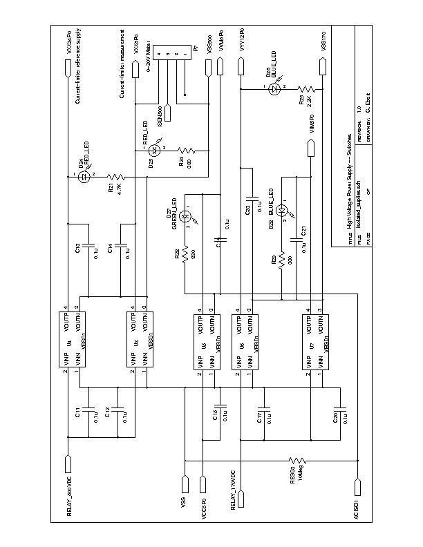
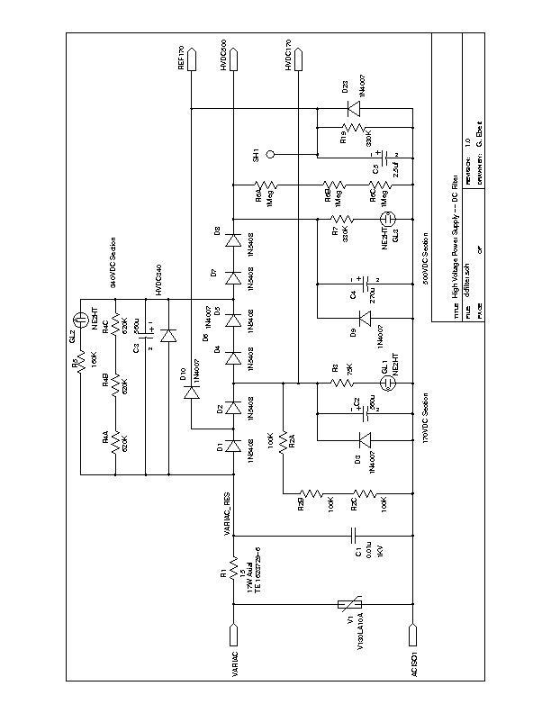
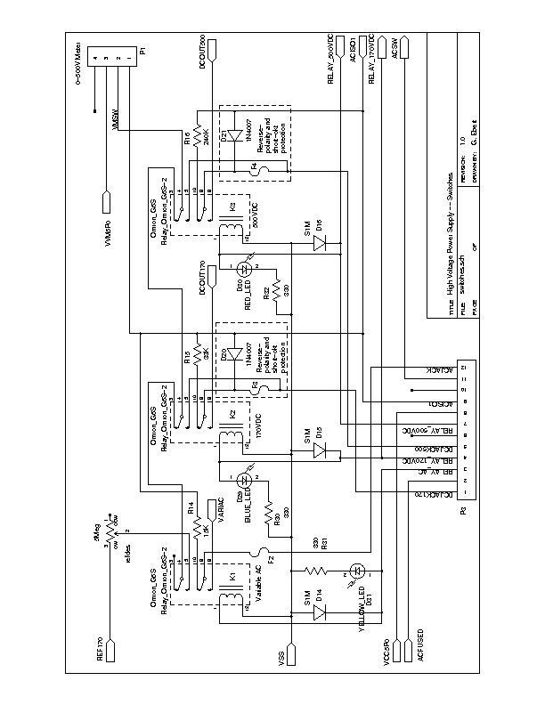
I've received requests for a total of 6 boards, which leaves only 1 remaining. I hope to get time this weekend to post private listings on Ebay. Once I get that setup I'll contact all who have shown interest. The price will be $10 US, and covers my costs for shipping/Ebay/paypal. I'm also working on the documentation as time permits; I'm horribly busy with my day-job so it may take a few days.
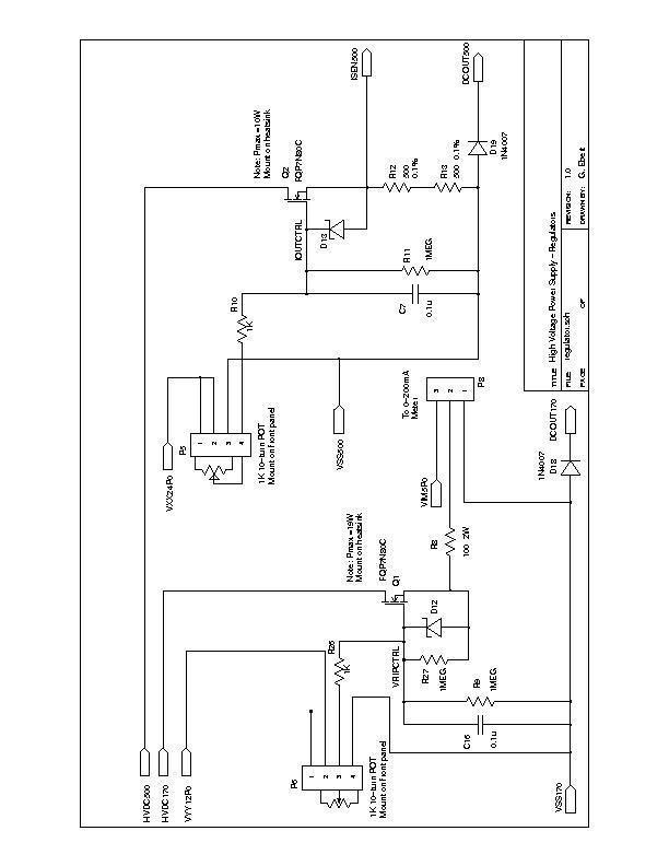
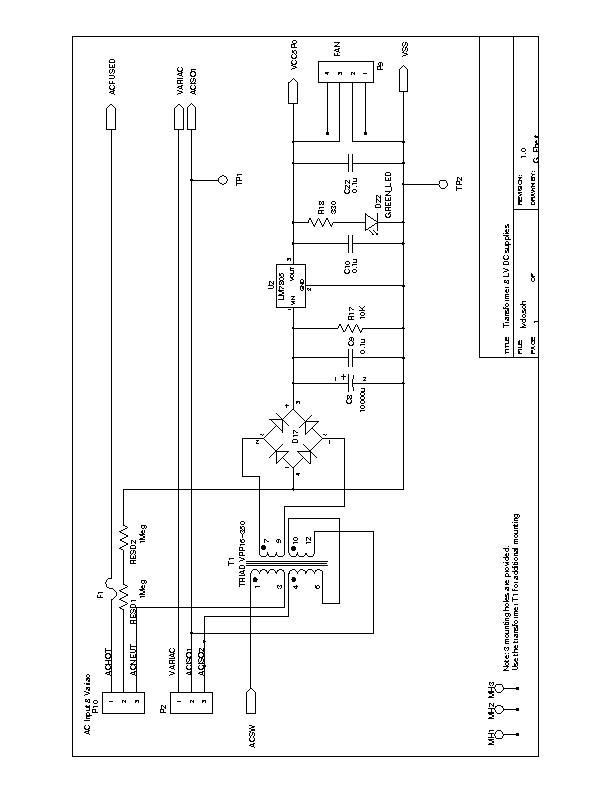
I'm posting the gerber files in case you want to view them, or fab on your own; I use gerbv (free) for viewing.
--
You received this message because you are subscribed to the Google Groups "neonixie-l" group.
To unsubscribe from this group and stop receiving emails from it, send an email to neonixie-l+unsubscribe@googlegroups.com.
To post to this group, send email to neoni...@googlegroups.com.
To view this discussion on the web, visit https://groups.google.com/d/msgid/neonixie-l/986a40d0-9c38-4df6-a590-7e41e52777d9%40googlegroups.com.
For more options, visit https://groups.google.com/d/optout.
--
You received this message because you are subscribed to the Google Groups "neonixie-l" group.
To unsubscribe from this group and stop receiving emails from it, send an email to neonixie-l+unsubscribe@googlegroups.com.
To view this discussion on the web, visit https://groups.google.com/d/msgid/neonixie-l/!%26!AAAAAAAAAAAYAAAAAAAAAPDddShx705MuX20yCpp0vvCgAAAEAAAAMQiS1jhO0xPhtXDpkjoF2EBAAAAAA%3D%3D%40zeelandnet.nl.
gregebert
Dekatron42

Samuel G. Guss
I second Martin's suggestion!
I think it would be a lot better if you kept the questions and answers here on this forum, so please reconsider.
/Martin
On Monday, 5 September 2016 06:55:26 UTC+2, gregebert wrote:
<snip>

jb-electronics
--
You received this message because you are subscribed to the Google Groups "neonixie-l" group.
To unsubscribe from this group and stop receiving emails from it, send an email to neonixie-l+...@googlegroups.com.
To post to this group, send email to neoni...@googlegroups.com.
To view this discussion on the web, visit https://groups.google.com/d/msgid/neonixie-l/d36b805d-bb10-63b2-dfde-d179371ed596%40fred.net.