Help with IN-8 tube mount for Threeneuron's 6 digit clock
213 views
Skip to first unread message

Jason Perez
Aug 19, 2016, 2:18:43 PM8/19/16
to neonixie-l
Hello all,
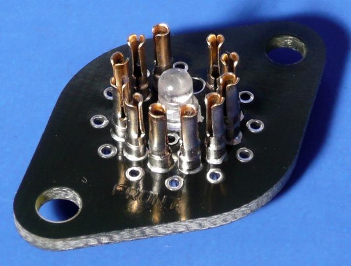
I am a new member. Quick background on me, I am a 29 year old engineering student looking to learn more about electronics. So I picked up Threeneuron's nixie clock kit on ebay. I am really enjoying putting it together and I was considering building a PCB to mount all of the nixies. Looking at the given schematic it seems like it should be fairly straightforward. Without using a board, looks like it would be a real rats nest. Was just wondering if anyone could help me out with the board. I have looked at a few "on demand" PCB manufacturers that offer their own software and none of them had any information on the IN-8 tubes. By the way I also ordered the LED bases for IN-8 tubes from the Nocrotec Shop on ebay. So if there were some way I could integrate all of that into a printed board that would be excellent! I just need some help! Hopefully someone here has done it before.... Schematic and a pic of the LED bases attached.

gregebert
Aug 19, 2016, 3:08:06 PM8/19/16
to neonixie-l
I use gEDA software (free) for my design work because it allows me to do simulations in verilog and spice, and the pcb files (including footprints) are all ascii-text, so you can create/modify them. There are several PCB vendors on Ebay that will make high-quality boards from your Gerber files for a reasonable price; on average $100 US for 5 boards roughly 8" x 8". Obviously you will pay more for multi-layer (ten 3"x4" cost me $200), or very large boards (five 14" x 14" cost me $300).
Other folks on this forum have used different PCB software; I'll let them chime-in on their experience.

John Rehwinkel
Aug 19, 2016, 9:34:33 PM8/19/16
to neoni...@googlegroups.com
I am a new member. Quick background on me, I am a 29 year old engineering student looking to learn more about electronics.
Excellent! Welcome aboard!
So I picked up Threeneuron's nixie clock kit on ebay. I am really enjoying putting it together and I was considering building a PCB to mount all of the nixies. Looking at the given schematic it seems like it should be fairly straightforward.
Yeah, as your schematic illustrates, nixie tube boards aren't very difficult.
Without using a board, looks like it would be a real rats nest. Was just wondering if anyone could help me out with the board. I have looked at a few "on demand" PCB manufacturers that offer their own software and none of them had any information on the IN-8 tubes.
Most of that software is nasty DOS-only stuff that locks you into those vendors.
By the way I also ordered the LED bases for IN-8 tubes from the Nocrotec Shop on ebay. So if there were some way I could integrate all of that into a printed board that would be excellent! I just need some help! Hopefully someone here has done it before.... Schematic and a pic of the LED bases attached.
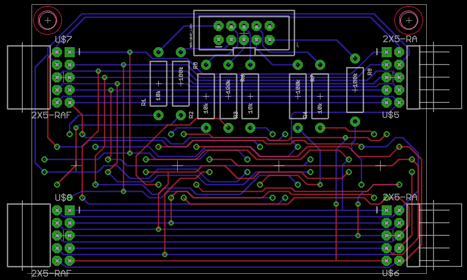
I design boards occasionally for various projects. I happen to use Eagle, which some board vendors accept directly, otherwise it can output industry-standard Gerber files which will work with the vast majority of vendors. I've even designed boards for IN-8 tubes (I created a custom part myself, as this design needed to fit certain specific parameters). If I can get the specifications for the Nocrotec sockets, I can make a custom part for them too. I've appended one of my IN-8 board designs to illustrate how my work tends to look. It's all hand routed, and an ordinary low-cost 2-layer board that doesn't use any tight spacings or fine wires that would make it more difficult or expensive to manufacture. It actually goes into a widget with 8 tubes, which uses two of these boards side by side (via the connectors on the ends), which gives even tube spacing when plugged together. It did it this way, because it's often cheaper to produce several small boards than one big one (for various reasons).
It does have one of the T joints that Terry warns about - my bad.
- John
Message has been deleted

Roddy Scott
Aug 20, 2016, 2:32:33 AM8/20/16
to neonixie-l
Hello Jason,
If you are using threeneuron's mounts as a remote connection you can use ribbon cable to supply them and mount them on a piece of plexiglass, a case or whatever. You would not have a rats nest as you can do an exceptionally neat connection this way and have a multi-pin connection from the ribbon to the driver board.
For a rats, nest see photo!

Jason Perez
Aug 20, 2016, 12:22:13 PM8/20/16
to neonixie-l
I design boards occasionally for various projects. I happen to use Eagle, which some board vendors accept directly, otherwise it can output industry-standard Gerber files which will work with the vast majority of vendors. I've even designed boards for IN-8 tubes (I created a custom part myself, as this design needed to fit certain specific parameters). If I can get the specifications for the Nocrotec sockets, I can make a custom part for them too. I've appended one of my IN-8 board designs to illustrate how my work tends to look. It's all hand routed, and an ordinary low-cost 2-layer board that doesn't use any tight spacings or fine wires that would make it more difficult or expensive to manufacture. It actually goes into a widget with 8 tubes, which uses two of these boards side by side (via the connectors on the ends), which gives even tube spacing when plugged together. It did it this way, because it's often cheaper to produce several small boards than one big one (for various reasons).
I will take a look at Eagle. I have done board layouts in AutoCad before but at the moment I don't have access to any cad software. I am sure there are much more useful tools for that kind of work anyway. Part of my hope is to integrate power for the blue LEDs on the Nocrotec sockets since there are no provisions for this in the kit. Looks like I may be able to get Eagle free under an educational license.
Jason Perez
Aug 20, 2016, 12:26:27 PM8/20/16
to neonixie-l
On Saturday, August 20, 2016 at 2:32:33 AM UTC-4, Roddy Scott wrote:
Hello Jason,If you are using threeneuron's mounts as a remote connection you can use ribbon cable to supply them and mount them on a piece of plexiglass, a case or whatever. You would not have a rats nest as you can do an exceptionally neat connection this way and have a multi-pin connection from the ribbon to the driver board.
True, I noticed the lighted socket mounts have screw mount holes so this would be a good back up plan. Would like to look into a board first, that would help me learn more about board design / manufacturing process.
Jason Perez
Aug 20, 2016, 12:32:17 PM8/20/16
to neonixie-l
On Friday, August 19, 2016 at 3:08:06 PM UTC-4, gregebert wrote:
I use gEDA software (free) for my design work because it allows me to do simulations in verilog and spice, and the pcb files (including footprints) are all ascii-text, so you can create/modify them. There are several PCB vendors on Ebay that will make high-quality boards from your Gerber files for a reasonable price; on average $100 US for 5 boards roughly 8" x 8". Obviously you will pay more for multi-layer (ten 3"x4" cost me $200), or very large boards (five 14" x 14" cost me $300).
Thanks! I will look into this as well.
By the way sorry if I'm not following post protocol, I'm new to google groups in general as well. Just call me on it if I'm not :)
Thanks everyone for the replies, I'm excited to have support! I'm sure I will have many more questions as I get into the design.
John Rehwinkel
Aug 20, 2016, 1:37:09 PM8/20/16
to neoni...@googlegroups.com
On Aug 20, 2016, at 12:22 PM, Jason Perez <jasonp...@gmail.com> wrote:I design boards occasionally for various projects. I happen to use Eagle, which some board vendors accept directly, otherwise it can output industry-standard Gerber files which will work with the vast majority of vendors. I've even designed boards for IN-8 tubes (I created a custom part myself, as this design needed to fit certain specific parameters). If I can get the specifications for the Nocrotec sockets, I can make a custom part for them too. I've appended one of my IN-8 board designs to illustrate how my work tends to look. It's all hand routed, and an ordinary low-cost 2-layer board that doesn't use any tight spacings or fine wires that would make it more difficult or expensive to manufacture. It actually goes into a widget with 8 tubes, which uses two of these boards side by side (via the connectors on the ends), which gives even tube spacing when plugged together. It did it this way, because it's often cheaper to produce several small boards than one big one (for various reasons).I will take a look at Eagle. I have done board layouts in AutoCad before but at the moment I don't have access to any cad software. I am sure there are much more useful tools for that kind of work anyway. Part of my hope is to integrate power for the blue LEDs on the Nocrotec sockets since there are no provisions for this in the kit. Looks like I may be able to get Eagle free under an educational license.
Yeah, the free version of Eagle is what I learned on. That's the other reason I split my 8-tube board into two 4-tube boards: the smaller boards fit into the free version of Eagle's size limitation. When I designed that board, I was still using the free version.
I'm willing to create an Eagle part for you for the Nocrotec sockets, with and/or without LED power. Creating parts in Eagle isn't too tough, but it can be a bit much for a beginner. I can heartily recommend SparkFun's tutorials on how to use Eagle (I'd start with Using EAGLE: Schematic and Using EAGLE: Board Layout):
Adafruit has a nice video on using EAGLE to route boards too:
- John
Jason Perez
Aug 22, 2016, 2:28:07 PM8/22/16
to neonixie-l
John,
That would be great! Yes i would like to include to include power for the leds, mounts sized for the nocrotec lighted sockets and a connection for the 20 pin ribbon cable from the main board. What would you charge for that?
That would be great! Yes i would like to include to include power for the leds, mounts sized for the nocrotec lighted sockets and a connection for the 20 pin ribbon cable from the main board. What would you charge for that?
John Rehwinkel
Aug 22, 2016, 2:56:57 PM8/22/16
to neoni...@googlegroups.com
> That would be great! Yes i would like to include to include power for the leds, mounts sized for the nocrotec lighted sockets and a connection for the 20 pin ribbon cable from the main board.
Note that the 20 pin cable doesn't include LED power. How do you want to power the LEDs? There is one unused pin, but you'd need two.
Do you want the ribbon cable plugged on the tube side or the other side of the board?
Do you want the colons like in that diagram? Do you have a pinout for your colon stacks?
Do you want the anode resistors on the board?
Do you want the LED current limiting resistors on the board?
Do you want the colon current limiting resistors on the board?
Is the 20 pin connector to be an ordinary 2x10 pin Berg connector (0.1" spacing)?
How far apart do you want your IN-8 tubes? The IN-8 socket data sheet recommends 23mm. Do you want them spaced differently around the colons?
Do you want mounting holes? If so, how many and where? Do you want the board to have any particular dimensions?
> What would you charge for that?
- John
John Rehwinkel
Aug 22, 2016, 4:40:00 PM8/22/16
to neoni...@googlegroups.com
> By the way I also ordered the LED bases for IN-8 tubes from the Nocrotec Shop on ebay. So if there were some way I could integrate all of that into a printed board that would be excellent!
Do you actually want to mount the Nocrotec sockets onto another PCB, or did you want a PCB that you can put the LEDs and IN-8s in directly? Since the Nocrotec sockets are actually just
small PCBs, it seems a little silly to mount them onto another PCB. I can of course, but I'm not sure if that's what you want.
- John
Jason Perez
Aug 22, 2016, 8:37:17 PM8/22/16
to neonixie-l
On Monday, August 22, 2016 at 2:56:57 PM UTC-4, jrehwin wrote:
Note that the 20 pin cable doesn't include LED power. How do you want to power the LEDs? There is one unused pin, but you'd need two.
Not sure on this. I knew I would have to solve this problem at some point and was hoping I could tie into the main board somewhere to draw power.
Do you want the ribbon cable plugged on the tube side or the other side of the board?
Opposite the tube side would be best, was planning to mount the board inside and have the tubes stick up through holes in a decorative case.
Do you want the colons like in that diagram? Do you have a pinout for your colon stacks?
For the colons, I was thinking of having them flash like option c.) below. I have not decided on a particular part for the colon. However these would be my first option, allspectrum.com INS-1.

Do you want the anode resistors on the board?
That would be great, on the underside with the connector if possible.
Do you want the LED current limiting resistors on the board?
Yes.
Do you want the colon current limiting resistors on the board?
Yes.
Is the 20 pin connector to be an ordinary 2x10 pin Berg connector (0.1" spacing)?
Not sure, I believe so? See threeneuron's part listing below:
![]()
How far apart do you want your IN-8 tubes? The IN-8 socket data sheet recommends 23mm. Do you want them spaced differently around the colons?
The recommended is fine. I had figured this would be the last priority in my design. The colons would probably require more space, not exactly sure yet.
Do you want mounting holes? If so, how many and where? Do you want the board to have any particular dimensions?
4, one in each corner would be fine. No specific dims, just as small as practical.
I will be able to give more intelligent answers to the these questions later, just wanted to get back to you tonight.
Jason Perez
Aug 22, 2016, 8:53:38 PM8/22/16
to neonixie-l
Right, I realize now it would be redundant. The first thing I wanted that lead me to the nocrotec sockets was, a socket of any kind. I wanted the ability to remove the IN-8's without de-soldering them. The lighted part was nice bonus. However, yes I suppose I could just use the sockets supplied with the nocrotec base kit and put them into your board. Basically I realized that this would not meet my desire to be neat and plug-and-play. To be able to go from the nixie tube contact pads through circuit traces to the ribbon cable.
Given the choice I would prefer to have a single integrated board and discard the six individual lighted socket boards I bought. A single board with integrated led's.
A note on the led power, depending on how I get power to the LED's perhaps you could run that part of the circuit to a separate two pin connector? Again, I'm not sure at this moment where I can tap into the main board for power.

Jeff Walton
Aug 22, 2016, 9:53:49 PM8/22/16
to neoni...@googlegroups.com
Or: For IN-8, you could just purchase a kit from Pete at PV Electronics. There are others. Already have lighted bases, robust menus, GPS support and established code. All on a nice clean board.
It's a fallback if you end up suffering from scope-creep when you realize how much work it takes to do a nice clean design.
Just a suggestion if life gets complicated. :)
--
You received this message because you are subscribed to the Google Groups "neonixie-l" group.
To unsubscribe from this group and stop receiving emails from it, send an email to neonixie-l+...@googlegroups.com.
To post to this group, send email to neoni...@googlegroups.com.
To view this discussion on the web, visit https://groups.google.com/d/msgid/neonixie-l/9648c4bb-c66d-4d36-8655-f0e1771b3de1%40googlegroups.com.
For more options, visit https://groups.google.com/d/optout.

electrofish
Aug 23, 2016, 8:09:57 AM8/23/16
to neonixie-l
Hello
I'm not quite a new member and have made quite a few kits (I'm a fairly successful kit builder) including a few Threeneurons and a couple of the Divergence meters. The Divergence meters took me some time because I have basic modelling skills and found getting the holes for the nixies evenly cut by hand very difficult but got there eventually.
I have exactly the same problem with the Threeneurons nixies as I have zero design ability so have been following this thread very closely as I hope to build two of the nixie dekatron kits, one as a 60th birthday present for a relative.
I also planned to use IN8 tubes with Nocrotec sockets and lighting. So if you go ahead with this design and make it available to others I for one would be delighted and grateful.
Also noted about PV's great kits being all complete as I've made a few of them too but none, to my knowledge, has the magic of a dekatron included.
Regards
John Sturgeon
John Rehwinkel
Aug 23, 2016, 11:57:46 AM8/23/16
to neoni...@googlegroups.com
Given the choice I would prefer to have a single integrated board and discard the six individual lighted socket boards I bought. A single board with integrated led's.
That makes sense.
A note on the led power, depending on how I get power to the LED's perhaps you could run that part of the circuit to a separate two pin connector? Again, I'm not sure at this moment where I can tap into the main board for power.
That makes sense too.
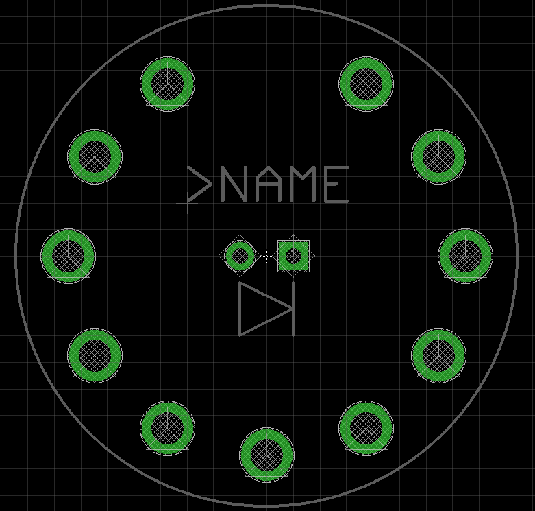
Accordingly, I've laid out an Eagle part for an IN-8 tube using the D-sub style spring pins (like the Nocrotec socket) along with an LED. It's also possible to use pins that are embedded in the board, but those are inflexible (can put stress on the tube seals), and they don't stick out of the board (so there's no room for an LED underneath). I'm not quite sure which pins the Nocrotec board is using or where to get them, but I used their dimensions to choose the hole size for them in this pattern. I made the LED leads 0.1" spacing, which should suit most common 3mm and 5mm LEDs.
The next step is to make a board with six of them, along with the colon pads, resistors, connectors, etc.
- John
gregebert
Aug 23, 2016, 12:32:51 PM8/23/16
to neonixie-l
A solution to the inflexible socket-pins soldered to the PCB is to custom-fit each tube. Assign a unique number to each tube and socket. Place the pins onto the tube, then solder the pins to the PCB (almost like soldering the tube in-place). Remove the tube, clip-off the extra leads on the PCB.
The tube can be inserted almost effortlessly, and with far less force than a conventional socket. My last clock has 18 sockets for IN-18's. "Only" 14 are actually populated, though. I found that even though each tube is custom fitted to a particular location, it's fairly easy easy to interchange them because the pins are manufactured with reasonable consistency. Most IN-18 pins are soft and easily bent, so be extra careful when handling, socketing, straightening, etc. Nevertheless, I do keep each tube in it's assigned socket.
If you have a 3D printer, make a socket-cap to slip over the soldered pins. It will provide some mechanical protection for the pins, and it makes insertion of tubes much easier. It will have the same appearance as a real socket.
John Rehwinkel
Aug 23, 2016, 5:53:32 PM8/23/16
to neoni...@googlegroups.com
Given the choice I would prefer to have a single integrated board and discard the six individual lighted socket boards I bought. A single board with integrated led's.
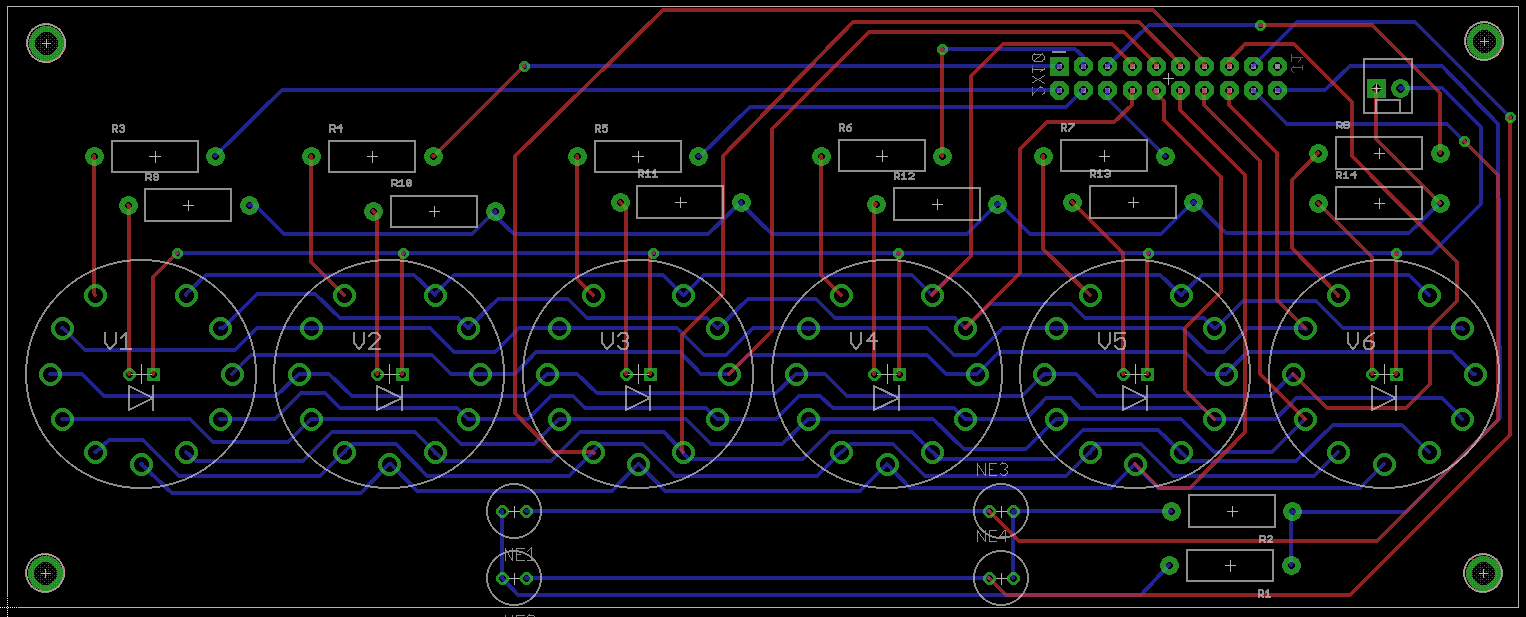
I made a first rough cut at it, and it looks totally doable. I tried to keep the high voltage wiring away from the LED wiring, and I didn't know how you'd be doing your colons, so I just put a pair of pads for each bulb. One simple approach is to just mount the upper bulb on a standoff with long wires.
- John
Jason Perez
Aug 23, 2016, 10:09:44 PM8/23/16
to neonixie-l
On Tuesday, August 23, 2016 at 5:53:32 PM UTC-4, jrehwin wrote:
I made a first rough cut at it, and it looks totally doable. I tried to keep the high voltage wiring away from the LED wiring, and I didn't know how you'd be doing your colons, so I just put a pair of pads for each bulb. One simple approach is to just mount the upper bulb on a standoff with long wires.
That looks great! I like the LED connector. Would it be possible to slide the colon pads in line between the tubes? Not sure how much space that would require or if your design area is big enough. I also see how busy the traces are in that area so if it's too much trouble that's ok!
Another question comes to mind, is there a certain width / thickness required for the traces since the nixies operate a 180 volts? I guess since current is only 3 mA it's not a big deal? If the ribbon cable wires are only 28 gauge I guess that answers my question.
Again great job on the board! So fast too! It's exactly as I had pictured!
Jason Perez
Aug 23, 2016, 10:17:37 PM8/23/16
to neonixie-l
On Monday, August 22, 2016 at 9:53:49 PM UTC-4, Jeff Walton wrote:
Or: For IN-8, you could just purchase a kit from Pete at PV Electronics. There are others. Already have lighted bases, robust menus, GPS support and established code. All on a nice clean board.It's a fallback if you end up suffering from scope-creep when you realize how much work it takes to do a nice clean design.Just a suggestion if life gets complicated. :)
Thanks! Wow those look really nice, crap i'm going to have to put one of those on my christmas list!
Jason Perez
Aug 23, 2016, 10:27:12 PM8/23/16
to neonixie-l
On Tuesday, August 23, 2016 at 8:09:57 AM UTC-4, electrofish wrote:
Hello
I'm not quite a new member and have made quite a few kits (I'm a fairly successful kit builder) including a few Threeneurons and a couple of the Divergence meters. The Divergence meters took me some time because I have basic modelling skills and found getting the holes for the nixies evenly cut by hand very difficult but got there eventually.
I have exactly the same problem with the Threeneurons nixies as I have zero design ability so have been following this thread very closely as I hope to build two of the nixie dekatron kits, one as a 60th birthday present for a relative.
I also planned to use IN8 tubes with Nocrotec sockets and lighting. So if you go ahead with this design and make it available to others I for one would be delighted and grateful.
Also noted about PV's great kits being all complete as I've made a few of them too but none, to my knowledge, has the magic of a dekatron included.
Regards
John Sturgeon
Thanks for the info. As it looks right now I will definitely be pursuing the integrated circuit board approach for my Threeneuron clock thanks to jrehwin! I will certainly keep the community updated if I do end up having this board manufactured maybe I can take an order and get a few. Yes the dekatron was what drew me to Threeneuron's kit, it's a nice touch!
Jason Perez
Aug 23, 2016, 10:37:05 PM8/23/16
to neonixie-l
I will keep this in mind for assembly. I did notice all of the pins are skewed in one direction on a couple of the tubes I ordered. Not sure exactly how you're supposed to straighten them, I saw a tube straightener on ebay but it was $150 or something......for a piece of metal? There has to be an easier way.
Roddy Scott
Aug 24, 2016, 3:37:10 AM8/24/16
to neonixie-l
Skewed in one direction means they were pulled out at an angle and this can lead to seal damage. Without a tube straightner you can gently straighten them with flat jawed needle pliers by applying as little force as possible to get them perpendicular again. I have done this without causing any compromise to the seal on quite a few tubes. The thicker the pin, the more likely the damage to the seal.
When Nixies were common place and replacements were widely available less care was taken with them in inserting and removing them by hamfisted individuals. Now that you have to pawn an arm or a leg for some tubes more care is taken!
I have Z566s on a PV Electronics board with the plexiglass mounts and these give a good grip on the pins and support to the nixie. I have used the same sockets without the plexiglass as 'flying' connections but only after shrouding them in heatshrink to stop them splaying open and causing poor or loose connections.
This thread has raised some very interesting points in regards to tube fitment.
Roddy Scott
Aug 24, 2016, 3:47:40 AM8/24/16
to neonixie-l

Jason Perez
Aug 24, 2016, 10:41:49 AM8/24/16
to neonixie-l
Roddy,
I will try that for pin straightening. I like the plexiglass, so the idea is that holds the sockets tightly closed?
I will try that for pin straightening. I like the plexiglass, so the idea is that holds the sockets tightly closed?
Roddy Scott
Aug 24, 2016, 4:02:27 PM8/24/16
to neonixie-l
Hi Jason,
the sockets are held tight as you say by this method. Have a look at the Assembly instructions for the Spectrum kit from PV Electronics for details.
Jason Perez
Aug 27, 2016, 3:13:09 PM8/27/16
to neonixie-l
John,
Just wondering how the eagle part is coming? I would be perfectly happy using your initial layout, it looks great! Could you attach the eagle file for me to look over? Not sure exactly what size your design is but hopefully i could open it with my student version of the program.
Just wondering how the eagle part is coming? I would be perfectly happy using your initial layout, it looks great! Could you attach the eagle file for me to look over? Not sure exactly what size your design is but hopefully i could open it with my student version of the program.

Joe Croft
Aug 27, 2016, 3:25:21 PM8/27/16
to neonixie-l
I'm a big gEDA person myself. I drank the linux kool-aid a long time ago and I do enjoy laying out my boards in a more manual way. It is reasonably easy to use makes nice boards and schematics and creating foot prints are very hard after the first one or two.
Good luck keeping your new addiction under control ;)On Fri, Aug 19, 2016 at 1:18 PM, Jason Perez <jasonp...@gmail.com> wrote:
Hello all,I am a new member. Quick background on me, I am a 29 year old engineering student looking to learn more about electronics. So I picked up Threeneuron's nixie clock kit on ebay. I am really enjoying putting it together and I was considering building a PCB to mount all of the nixies. Looking at the given schematic it seems like it should be fairly straightforward. Without using a board, looks like it would be a real rats nest. Was just wondering if anyone could help me out with the board. I have looked at a few "on demand" PCB manufacturers that offer their own software and none of them had any information on the IN-8 tubes. By the way I also ordered the LED bases for IN-8 tubes from the Nocrotec Shop on ebay. So if there were some way I could integrate all of that into a printed board that would be excellent! I just need some help! Hopefully someone here has done it before.... Schematic and a pic of the LED bases attached.
--
You received this message because you are subscribed to the Google Groups "neonixie-l" group.
To unsubscribe from this group and stop receiving emails from it, send an email to neonixie-l+unsubscribe@googlegroups.com.
To post to this group, send email to neoni...@googlegroups.com.
To view this discussion on the web, visit https://groups.google.com/d/msgid/neonixie-l/ab7101de-2aca-4371-a97a-00c17d519d41%40googlegroups.com.
John Rehwinkel
Aug 27, 2016, 4:21:12 PM8/27/16
to neoni...@googlegroups.com
Just wondering how the eagle part is coming? I would be perfectly happy using your initial layout, it looks great! Could you attach the eagle file for me to look over? Not sure exactly what size your design is but hopefully i could open it with my student version of the program.
I've been swamped at work, so I haven't made further progress. I think I may have some sizes wrong.
The schematic is here:
The board is here:
- John
Jason Perez
Aug 27, 2016, 10:39:49 PM8/27/16
to neonixie-l
No problem, good to hear from you again, I was hoping you didn't disappear! . I will take a look through the files and familiarize myself with eagle once I get it downloaded. Should be approved for the educational edition early next week.
Jason Perez
Aug 27, 2016, 11:04:17 PM8/27/16
to neonixie-l
Thanks for the input. Yea that's a new one I've never heard of, looks like a decent program. Haha yea, I love nixies! It's a great hobby for me right now, after doing fluid mechanics all day I just spend a couple hours soldering :)
On that note, my dekatron tubes came friday! What a gorgeous piece of engineering. Can't wait till they're powered up!

Jason Perez
Sep 12, 2016, 11:34:23 AM9/12/16
to neonixie-l
Still have not looked over the eagle files, I was able to open them with my student license. I'm busy with classes since the fall semester started. Hopefully will spend some time getting to know eagle over the next few weeks and be able to make some edits on the nixie board.
Reply all
Reply to author
Forward
0 new messages