Maybe a stupid question...
196 views
Skip to first unread message

karl welty
Aug 15, 2016, 5:08:49 PM8/15/16
to neoni...@googlegroups.com
Greetz,
Since my emphasis with neon circuits lean towards musical synthesis I
am always on the hunt for interesting counting circuits. I often will
circuit bend them a bit to be more random, and often will include
potentiometers to allow me to mess up their timing. Its the antithesis
of accuracy or stability, but I have a great deal of fun with it.
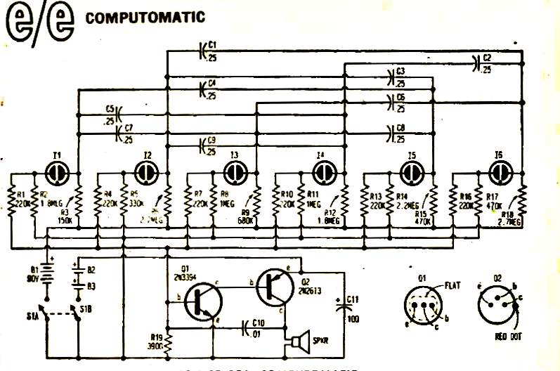
I thought I would take a stab at the enclosed circuit. I built up the
capacitor network, included the lamps (NE-2's) and one of its two
buses. I had six 470k resistors. I have an alternate idea for the two
transistor circuit shown, so I was simply working on the counting
portion.
The article describes it as a "do nothing circuit" and except for a
few variations thats sadly the case. The lamps do not dance. Once one
latches it remains lit. Slightly increasing or decreasing the supply
voltage will cause other lamps to fire once. I tried a pulsed supply
through an NE-2 LFO element, a bit of joy but nowhere near a range of
options. I've also tried a variety of resistor values such as shown,
still no cycling joy.
I am now wondering if my choice of non-polarized caps is to blame ?
Would a diode in series with each cap help matters ? I lacked 0.25's
but had 0.22's as they seemed close enough to at least demonstrate the
circuit.
Or... as an alternative... if the cap matrix shown were diodes, and
instead have a cap parallel to the lamp to pulse it, might that yield
some random dancing joy ?
Momentarily stumped. But if there are folks who understand counting
circuits, that would be here.
Since my emphasis with neon circuits lean towards musical synthesis I
am always on the hunt for interesting counting circuits. I often will
circuit bend them a bit to be more random, and often will include
potentiometers to allow me to mess up their timing. Its the antithesis
of accuracy or stability, but I have a great deal of fun with it.
I thought I would take a stab at the enclosed circuit. I built up the
capacitor network, included the lamps (NE-2's) and one of its two
buses. I had six 470k resistors. I have an alternate idea for the two
transistor circuit shown, so I was simply working on the counting
portion.
The article describes it as a "do nothing circuit" and except for a
few variations thats sadly the case. The lamps do not dance. Once one
latches it remains lit. Slightly increasing or decreasing the supply
voltage will cause other lamps to fire once. I tried a pulsed supply
through an NE-2 LFO element, a bit of joy but nowhere near a range of
options. I've also tried a variety of resistor values such as shown,
still no cycling joy.
I am now wondering if my choice of non-polarized caps is to blame ?
Would a diode in series with each cap help matters ? I lacked 0.25's
but had 0.22's as they seemed close enough to at least demonstrate the
circuit.
Or... as an alternative... if the cap matrix shown were diodes, and
instead have a cap parallel to the lamp to pulse it, might that yield
some random dancing joy ?
Momentarily stumped. But if there are folks who understand counting
circuits, that would be here.

gregebert
Aug 15, 2016, 6:00:05 PM8/15/16
to neonixie-l
I've seen neon circuits similar to this, where the lamps fire sequentially rather than randomly. Last time I built one was a Radio Shack 'PBOX' kit in the mid 1970's. This circuit is different because it has 6 bulbs instead of 5, and the audio section.
I would triple-check the capacitor connections because a mistake is very easy here and it will likely cause the circuit to latch rather than oscillate as it should. (reminds me of the joke about one EE griping that his amplifier only oscillates, and the other EE who complains his oscillator only amplifies....).
Thanks for posting the schematic; I lost my copy years ago and never spent the time to find it and understand how it works. Now I will.
karl welty
Aug 15, 2016, 6:18:10 PM8/15/16
to neoni...@googlegroups.com
Oh yes, I've checked the cap wiring probably 2 dozen times over the
last couple days and its per the schematic. Hence the head scratching.
The supply resistor values and the ground path resistor values vary
wildly, perhaps it only works with such an exaggerated mis-match ?
I am only firmly at guessing. ;)
last couple days and its per the schematic. Hence the head scratching.
The supply resistor values and the ground path resistor values vary
wildly, perhaps it only works with such an exaggerated mis-match ?
I am only firmly at guessing. ;)
karl welty
Aug 15, 2016, 6:39:36 PM8/15/16
to neoni...@googlegroups.com
Another thought, a polarized cap can represent a short when reversed.
Could the circuit be dependent on this attribute ? Its showing voltage
being applied in either direction. In theory thats doomed to eventual
failure (?) So capacitance/resistance in one direction, and a short in
the other ?
Could the circuit be dependent on this attribute ? Its showing voltage
being applied in either direction. In theory thats doomed to eventual
failure (?) So capacitance/resistance in one direction, and a short in
the other ?
gregebert
Aug 17, 2016, 4:58:28 PM8/17/16
to neonixie-l
After studying the circuit, I'm fairly certain the way it works is that when a particular bulb fires, the other bulbs that are capacitively coupled to it will extinguish. Neon bulbs have built-in hysteresis (firing voltage is higher than sustaining voltage), which means that circuits can be constructed that self-oscillate.
So, back to debugging, if the capacitors are leaky I think it could prevent oscillation. Also, I'm not sure what resistors R2, R5, R8, R11, R14, and R17 do, so you may want to snip them off temporarily for debug. I dont think the transistor circuit will cause any interference.
karl welty
Aug 18, 2016, 6:32:47 AM8/18/16
to neoni...@googlegroups.com
I've been pondering it. Looking at the resistors for lamp one... R1
goes through a 220k to the bus which feeds the transistor oscillator.
Each resistor from each lamp circuit is the same to this bus. R2 acts
in conjunction with R1 as a voltage divider between the oscillator bus
and the ground bus for the lamps. R3 comes from the power bus. R1/R2,
the lamp and R3 are in series.
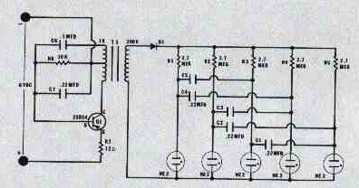
In the enclosed drawing of a previous counting circuit I've built with
success I found that if the resistor values were equal the circuit
would count in an orderly sequence of one through five and repeat. If
those values were changed with pots, it would alter the timing and the
sequence of firing. Removing some feeds caused those legs in the
counter to skip.
I've noticed a pattern to the resistor values of R2/R3, R5/R6, etc. L1
hi/lo - L2 lo/hi - L3 hi/lo - L4 lo/hi - L5 hi/lo - L6 lo/hi. A
variety of values but the relationship remains the same with either a
group of high values or low values. The total series/parallel values
of R1/R2-lamp-R3
are not equal.
The caps are not sequential from L1 thru L6, but scatter to the lamps
in 3, 4 or 5 bus spreads. The caps are all equal value.
From previous experience either of these changes (R or C with one
remaining constant) would cause a counting circuit to randomize, or at
the very least not count sequentially with equal length firings.
Altering the cap sequence changes the firing order as well.
Since I used 0.22 caps instead of 0.25's as the schematic indicated,
it is possible that even with exact resistor values as indicated it
might not oscillate. So my current plan is to hook up trimmers. A
"low" version (1meg pot with 100k in series) with a range of 100k to
1.1meg, and a "high" version (1meg pot with 1meg in series, and a spst
switch with 1meg on the legs) for a 1meg to 3meg range.
At least thats my plan tonight. Now to think on it some more.
goes through a 220k to the bus which feeds the transistor oscillator.
Each resistor from each lamp circuit is the same to this bus. R2 acts
in conjunction with R1 as a voltage divider between the oscillator bus
and the ground bus for the lamps. R3 comes from the power bus. R1/R2,
the lamp and R3 are in series.
In the enclosed drawing of a previous counting circuit I've built with
success I found that if the resistor values were equal the circuit
would count in an orderly sequence of one through five and repeat. If
those values were changed with pots, it would alter the timing and the
sequence of firing. Removing some feeds caused those legs in the
counter to skip.
I've noticed a pattern to the resistor values of R2/R3, R5/R6, etc. L1
hi/lo - L2 lo/hi - L3 hi/lo - L4 lo/hi - L5 hi/lo - L6 lo/hi. A
variety of values but the relationship remains the same with either a
group of high values or low values. The total series/parallel values
of R1/R2-lamp-R3
are not equal.
The caps are not sequential from L1 thru L6, but scatter to the lamps
in 3, 4 or 5 bus spreads. The caps are all equal value.
From previous experience either of these changes (R or C with one
remaining constant) would cause a counting circuit to randomize, or at
the very least not count sequentially with equal length firings.
Altering the cap sequence changes the firing order as well.
Since I used 0.22 caps instead of 0.25's as the schematic indicated,
it is possible that even with exact resistor values as indicated it
might not oscillate. So my current plan is to hook up trimmers. A
"low" version (1meg pot with 100k in series) with a range of 100k to
1.1meg, and a "high" version (1meg pot with 1meg in series, and a spst
switch with 1meg on the legs) for a 1meg to 3meg range.
At least thats my plan tonight. Now to think on it some more.

Dekatron42
Aug 18, 2016, 9:28:52 AM8/18/16
to neonixie-l
Have you read the original magazine article? If not I have included it here.
They mention that you need the correct neons to get the circuit to work as the resistors are chosen for those neons. Apart from that I also think that you will have to burn-in your neons so that you know that they strike at the correct voltage, so they work in the circuit with the chosen resistor values.
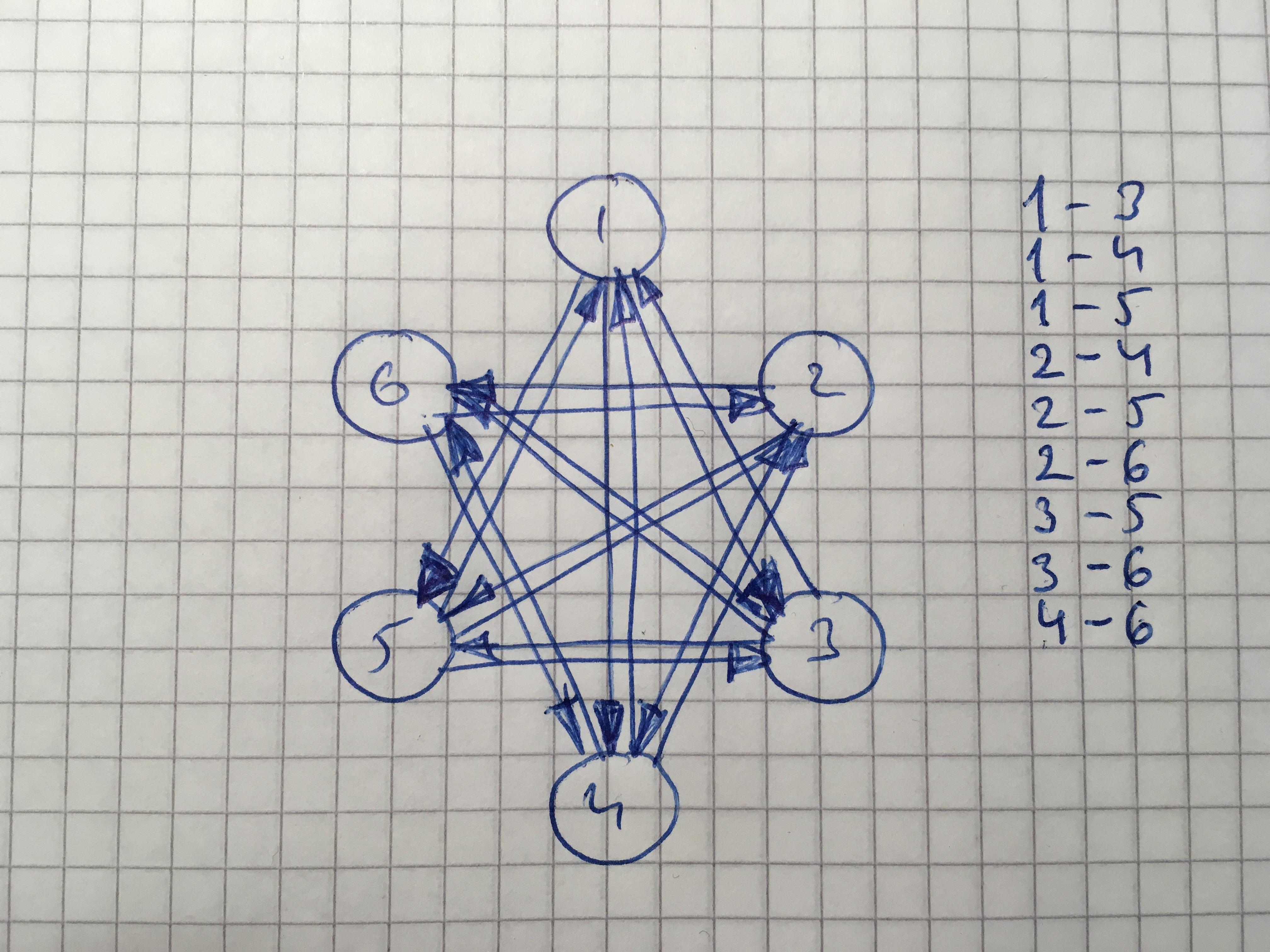
The circuit in itself can be drawn as a star with six points, almost like a state machine diagram, where each point is each neon, then you can draw arrows between the points connecting them in the same way as the capacitors are connected - then you can see how the circuit works by which neon affects the other neons somewhat more simpler than in the straightly drawn circuit diagram. The circuit can be seen as a series of flip-flops or as a modified ring-counter.
/Martin
karl welty
Aug 18, 2016, 1:46:32 PM8/18/16
to neoni...@googlegroups.com
Indeed I have been gathering clues from the complete article, though
drawing the circuit out in a different fashion might help me wrap my
head around it better ! Thanks for the tip.
drawing the circuit out in a different fashion might help me wrap my
head around it better ! Thanks for the tip.
karl welty
Aug 19, 2016, 3:24:58 PM8/19/16
to neoni...@googlegroups.com
Thanks ! I had just got the pen out at work and was planning on
drawing it. Yes that is very helpful to see whats going on. It also
gave me inspiration to draw out an alternate circuit which in
retrospect is much more along the lines of the function I wanted a
circuit to perform. I havent given up on the "computomatic" and shant
be stripping the parts off the board right away, but the alternate
direction seems (maybe) more suited anyways. I'll post something when
its better documented.
Thanks a zillion for the help on this one folks !

threeneurons
Aug 19, 2016, 9:31:36 PM8/19/16
to neonixie-l
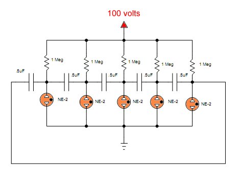
At least thats my plan tonight. Now to think on it some more.
That's not counter, but free running sequencer. Here's the same circuit, redrawn:

The sequence pattern, is in the form of a star.
Here's a video of it running:
The first time, I saw this circuit, was from a Radio Shack P-Box kit, I purchased, back in high school. That would be in the 70's.

John Rehwinkel
Aug 19, 2016, 9:39:47 PM8/19/16
to neoni...@googlegroups.com
Yup. Here's the schematic from the original Radio Shack "Goofy Lite" kit.
- John
gregebert
Aug 20, 2016, 12:56:16 AM8/20/16
to neonixie-l
I built every Pbox kit Radio Shack sold, and this one was definitely my favorite. The DC-DC converter made a slight whine that sounded like a mosquito. It took several weeks to scrape-up $5.95 USD from my meager allowance before I could buy it.
That kit was a turning-point for me, because ever since then I cannibalized electronic devices for their neon bulbs. 2 years later I got a piece of surplus test equipment that had 6 nixie tubes, and the rest is history....
karl welty
Aug 22, 2016, 1:11:16 AM8/22/16
to neoni...@googlegroups.com
With the parts order having arrived I was able to hook up the circuit
per my idea. It works exactly as I hoped it would. Thousands
(seemingly) of variations based on the settings of the pots. It
outputs a changing voltage right in the range of the intended VCO I
plan to have downstream. Initial testing mostly complete I can now
build up the VCO card and determine the best way to interface them. It
was a long week, this was a nice way to round out the weekend.
https://youtu.be/GGKjt8f74bw

Quixotic Nixotic
Aug 22, 2016, 2:28:18 AM8/22/16
to neoni...@googlegroups.com
Excellent work Karl. Very interesting and its always good to get the desired result in the end. I am following your progress with great interest.
John S
John S
karl welty
Aug 25, 2016, 2:45:22 AM8/25/16
to neoni...@googlegroups.com
Now I'm trying to figure out why the VCO I just built functions in
reverse. Positive CV input yields only horrible noise yet a negative
voltage of 0 to -12 creates a robust sounding sawtooth wave. I would
have thought it the other way around. Checked the connections dozens
of times, re-checked the schematic and board, doubted my supply and
meter so I tried a 9v battery and the same results... +vdc to the CV
input yields nothing yet -vdc makes it oscillate. Odd. I am pondering
an inverter circuit ahead of the CV input as my CV source would be 0
to a positive value. Thats outside the scope of here, but an
interesting detour along the journey.
gregebert
Aug 25, 2016, 4:08:30 PM8/25/16
to neonixie-l
You could try running a SPICE (analog) simulation on the circuit. I do that on all of my designs, and fiddle with component values to ensure the design is robust.
LTspice is available free for PC's; ngspice is also free and runs on Linux.
karl welty
Aug 25, 2016, 4:46:41 PM8/25/16
to neoni...@googlegroups.com
I need to have a look at the data sheet for the LM118H again. I didnt
hook up any of the compensation pins. I used V+, V-, In+, In-, and
Out. Maybe there's a clue there ? I used two of them instead of the
TL072 shown.
Simulation ? Sounds intriguing, and only slightly like "cheating" ;)
hook up any of the compensation pins. I used V+, V-, In+, In-, and
Out. Maybe there's a clue there ? I used two of them instead of the
TL072 shown.
Simulation ? Sounds intriguing, and only slightly like "cheating" ;)
karl welty
Aug 25, 2016, 5:50:25 PM8/25/16
to neoni...@googlegroups.com
LM118 is in the Spice parts list, I'll have a go at it later.
gregebert
Aug 25, 2016, 6:19:16 PM8/25/16
to neonixie-l
Simulations definitely are not cheating; I've found many non-obvious bugs that would have caused problems ranging from unreliable operation, to non-functional, and even smoke/fire.
My last project (nixie/dekatron bench power supply) was not properly simulated and I ended up with minor PCB workarounds for the first time; none of my previous PCBs had bugs because they were thoroughly simulated.
John Rehwinkel
Aug 25, 2016, 7:14:30 PM8/25/16
to neoni...@googlegroups.com
> Be curious... I built it exactly per the schematic with the exception
> of LM118's instead of a TL072 as shown. So... why it operates in an
> inverse fashion... yeah, maybe some simulation is called for !
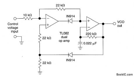
The VCO itself (the right-hand op amp) looks fairly conventional. However, the left-hand op amp and the diodes look weird to me. If I were you, I'd try hooking the control voltage directly to the + input of the right hand op amp and omit the rest of it. If you have an LM331 on hand, you can just use that.
> of LM118's instead of a TL072 as shown. So... why it operates in an
> inverse fashion... yeah, maybe some simulation is called for !
- John

David Forbes
Aug 25, 2016, 7:18:37 PM8/25/16
to neoni...@googlegroups.com
Karl,
The LM118 has a dramatically different input circuit than the TL072. This VCO
cirucit is decidedly non-linear in its operation, as it has diodes in the signal
paths. Thus, the input circuit behavior will have an effect.
Do not be surprised that this amplifier substitution could cause trouble.
--
David Forbes, Tucson, AZ
The LM118 has a dramatically different input circuit than the TL072. This VCO
cirucit is decidedly non-linear in its operation, as it has diodes in the signal
paths. Thus, the input circuit behavior will have an effect.
Do not be surprised that this amplifier substitution could cause trouble.
David Forbes, Tucson, AZ
karl welty
Aug 27, 2016, 3:58:36 PM8/27/16
to neoni...@googlegroups.com
In a very cobbled fashion (clip leads) I tried the two sections
together. Over a period of a couple hours of knob twiddling they
yielded a variety of sounds reminiscent of a vintage pinball machine,
or at the least old school video games. The vast majority of the knob
settings however yielded what even I would consider mostly unusable
noise. BUT the purpose of this experiment was more proof of concept
than finished circuit or components. A neon based timing and voltage
source can be used as a CV source for a VCO downstream.
In operation with the crude vco circuit I had built, the A opamp seems
to also function as a gate... or somehow, discrete gating is occurring
with the bits in context. All my prior attempts at gating a neon based
relaxation oscillator have resulted in pitch ramping up and down with
hang after the gate closed. I was getting distinct note on/off with no
pitch drift. So thats a first, and lots of other stuff learned as
well.
It doesnt work as intended, but the lesson continues and there are
tweaks to try. Change up the vco circuit. Big fun.
karl welty
Aug 27, 2016, 4:04:13 PM8/27/16
to neoni...@googlegroups.com
@John - which of the additional components would remain ? Just the
feedback resistor and cap, or any of the rest of it as well. Napkin
drawing ?
feedback resistor and cap, or any of the rest of it as well. Napkin
drawing ?
karl welty
Aug 31, 2016, 2:31:16 AM8/31/16
to neoni...@googlegroups.com
I've happily managed to get the two blocks talking with each other.
Went back to a previous oscillator I'd built, made a mod to its
feedback and have arrived at initial proof of concept. The vid shows
it only partially connected (3 of 6 lamp legs). It can be adjusted in
a variety of ways which create changes in its musical content. Time to
start pondering the user interface, build up the real boards or at
least figure out what aspect to tackle next. This evening is a bit
about basking and chocolate.
https://youtu.be/YoG2T5PRhd4
Reply all
Reply to author
Forward
0 new messages