IV-25 VFD Nixie Matrix tube project
852 views
Skip to first unread message

Hugh Pryor
Aug 18, 2015, 4:06:18 PM8/18/15
to neonixie-l

Hi there,
I just joined so perhaps I better introduce myself - I'm Hugh and I've gone and bought twenty IV-25 (or IVLM-1/7?) tubes thinking that this would be the start of an excellent project to make a small dot matrix display.
I've recently built an LED light wand with an arduino nano and I think this would be the logical next step.
I've learned a little about soldering, power regulators, programming the arduino and reading memory cards.
Not much experience but I've been bitten by the bug!
If I can get them working I'd like to make something that can display scrolling text and small animations, either reading from a memory card or directly from a computer.
So where do I start?
Testing them might be a good - so a 2.4V filament voltage and a 25V anode supply.
And then I need to figure out how to attach them to a board as an addressable matrix, and somehow magic some electricities from an arduino to drive a current through the tubes.
I guess I have a steep learning curve in front of me - which is exactly why I want to do this.
If you can point me in the right direction that would be brilliant!
Cheers,
Hugh

Terry Kennedy
Aug 19, 2015, 12:50:17 AM8/19/15
to neonixie-l
On Tuesday, August 18, 2015 at 4:06:18 PM UTC-4, Hugh Pryor wrote:
I guess I have a steep learning curve in front of me - which is exactly why I want to do this.
If you can point me in the right direction that would be brilliant!
I believe the IV-25 are like the IV-26 and don't have a control grid. That means you can't multiplex the tubes but need a driver for each dot (instead of having 7 dot drivers and a driver for each tube's grid). That makes constructing large displays out of these tubes rather unwieldy. The main use for the IV-26 tubes, the Elektronika 7 series of clocks, "cheated" by tying some dots together and leaving other dots unconnected as they would never be lit on the clock.
If you decide to move up to the larger IV-26 tubes, be aware that there are 3 types. Type 1 has all of the individual dots brought out separately. Type 2 is for a horizontal group of 12 (or 11) tubes, while Type 3 is for a vertical group of 4 tubes. Types 2 and 3 have dots tied together inside the tube.
The brightness curve for the IV-26 is somewhat unsatisfactory - the dots don't illuminate evenly until 100 hours or so of operation, and after a few thousand hours they start to fade. I don't know if the IV-25 behaves the same way, but before you start thinking there might be a problem with your design, let the tubes stabilize for a while.
Just about everything you might want to know about the IV-26 / Elektronika can be found on my blog: https://www.tmk.com/blog/?s=elektronika

Alex
Aug 19, 2015, 2:01:48 PM8/19/15
to neonixie-l
You may get inspiration from the clock kit that I occasionally see for sale on ebay that has 5 or 6 of these in vertical columns, scrolling 5x7 pixel font digits for a clock. I had similar thoughts to yourself a few years ago and bought a load of IV26 tubes, but unfortunately bought either type 2 or 3 (cant remember which) so shelved it... Dreaming up projects is so much easier than building them!
Good luck,
- Alex
Alex
Aug 21, 2015, 12:48:19 PM8/21/15
to neonixie-l
Mich...@aol.com
Aug 21, 2015, 12:56:10 PM8/21/15
to neoni...@googlegroups.com
I really like the clock (kit); however, priced just a little high for
me.
Auctions are buy now. Can't even make an offer. :(
Michail
--
You received this message because you are subscribed to the Google Groups "neonixie-l" group.
To unsubscribe from this group and stop receiving emails from it, send an email to neonixie-l+...@googlegroups.com.
To post to this group, send email to neoni...@googlegroups.com.
To view this discussion on the web, visit https://groups.google.com/d/msgid/neonixie-l/e629e2af-63cf-459f-ba67-7edb660adddb%40googlegroups.com.
For more options, visit https://groups.google.com/d/optout.

gregebert
Aug 21, 2015, 1:34:30 PM8/21/15
to neonixie-l
For those of you who have "see-through" clocks, like the VFD unit pictured above, does the appearance improve if you place something opaque behind the tubes, such black plastic ? For me, the clock's display gets obscured by the visible objects in the background.
To-date, every clock I've built uses 'top-view' tubes so there isn't any distraction from the background.
Hugh Pryor
Aug 24, 2015, 9:35:17 AM8/24/15
to neonixie-l
Thanks for the replies - that's all useful - particularly about the problem with multiplexing and the kit available.
I enjoyed reading Terry's Electronika clock restoration pages.
I would be interested to know what components were used in the kit - would they use the tubes with the joined together spots like in the Electronika clock?
Is the problem with multiplexing to do with requiring a pulsed current through the tubes? Would that shorten the life span?
I was talking to someone who suggested that I used relays to provide the current and shift registers to control the illumination of the dots. The relays would make a noise which would make it more interesting, and possibly quite annoying depending on how much noise.
Would it be possible to vary the illumination of the dots for greyscale values? If so would it be with pulsed width modulation (PWM), or controlling the voltage?
From what I understand it's technically quite tricky even with LEDs because our perception of brightness is logarithmic. However a crude 2-bit with 4 shades (including off) would improve the appearance of animations.
Still haven't checked if they work or not!
Hugh
From what I understand it's technically quite tricky even with LEDs because our perception of brightness is logarithmic. However a crude 2-bit with 4 shades (including off) would improve the appearance of animations.
Still haven't checked if they work or not!
Hugh
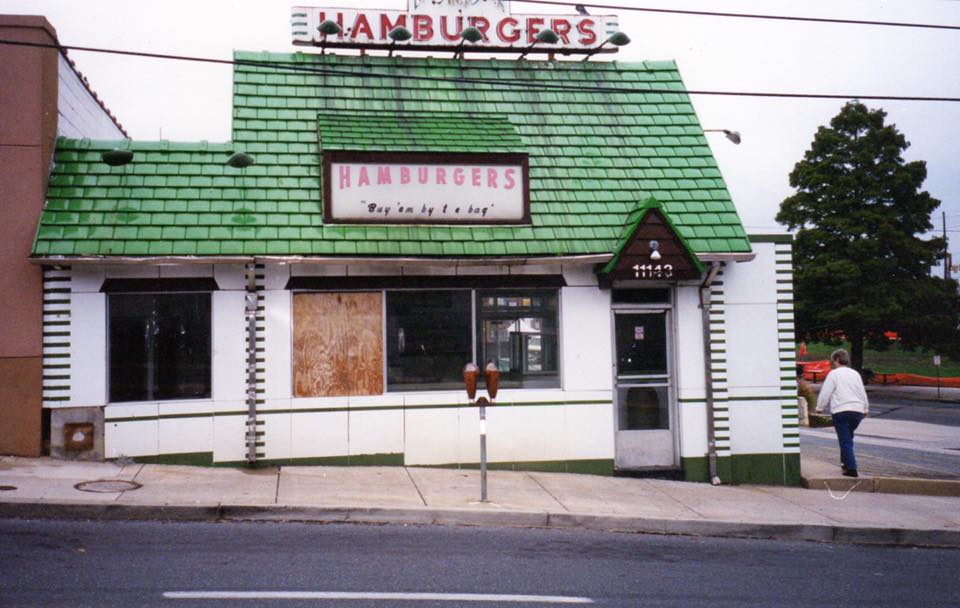
Quixotic Nixotic
Aug 24, 2015, 11:48:36 AM8/24/15
to neoni...@googlegroups.com
The owner of this burger joint took it to pieces in 1997. The sign is now for sale for US $18,000. Sale includes the green roof tiles and white porcelain panels.
The person selling claims $7,000 has already been spent on restoring the neon.
It seems expensive to me. Do people really pay these prices?
John S


NeonJohn
Aug 24, 2015, 2:31:55 PM8/24/15
to neoni...@googlegroups.com
world's expert on antique neon signs.
My guess is that he'll be lucky to get $2-3000 out of it if NONE of the
neon units are broken. Someone MIGHT pay a few hundred dollars for the
flat signs IFF they're porcelain. If they're painted, maybe a hundred
or so. The green tiles will end up being scrap metal.
John
--
John DeArmond
Tellico Plains, Occupied TN
http://www.fluxeon.com <-- THE source for induction heaters
http://www.neon-john.com <-- email from here
http://www.johndearmond.com <-- Best damned Blog on the net
https://www.etsy.com/shop/BarbraJoanOriginals <-- please visit
PGP key: wwwkeys.pgp.net: BCB68D77
Quixotic Nixotic
Aug 24, 2015, 4:17:23 PM8/24/15
to neoni...@googlegroups.com
On 24 Aug 2015, at 19:31, NeonJohn wrote:
>
>
> On 08/24/2015 11:48 AM, Quixotic Nixotic wrote:
>> The owner of this burger joint took it to pieces in 1997. The sign is now for
>> sale for US $18,000. Sale includes the green roof tiles and white porcelain panels.
>>
>> The person selling claims $7,000 has already been spent on restoring the neon.
>>
>> It seems expensive to me. Do people really pay these prices?
>
> NO! They don't. I'm forwarding this to Len Davidson, probably the
> world's expert on antique neon signs.
>
> My guess is that he'll be lucky to get $2-3000 out of it if NONE of the
> neon units are broken. Someone MIGHT pay a few hundred dollars for the
> flat signs IFF they're porcelain. If they're painted, maybe a hundred
> or so. The green tiles will end up being scrap metal.
>
> John
Would it have cost 7,000 bucks to have that neon tubing replaced? Or did they go to the wrong person?
John S
NeonJohn
Aug 24, 2015, 5:53:18 PM8/24/15
to neoni...@googlegroups.com
> Would it have cost 7,000 bucks to have that neon tubing replaced? Or
> did they go to the wrong person?
double stroke block letters, figure $35-50 a letter, depending on size.
Some benders price by the foot and number of bends but I simplified
letter prices to just the height and the number of strokes. Comes out
about the same.
There would also be crane time for installing the letters in situ.
It doesn't look like any repainting or can touchup was done.
If the sign needed new transformers and internal wiring, maybe that high
a price could be justified but that's a lot more money than I could get
around here.
Terry Kennedy
Aug 25, 2015, 1:04:53 AM8/25/15
to neonixie-l
On Monday, August 24, 2015 at 9:35:17 AM UTC-4, Hugh Pryor wrote:
Thanks for the replies - that's all useful - particularly about the problem with multiplexing and the kit available.I enjoyed reading Terry's Electronika clock restoration pages.
I would be interested to know what components were used in the kit - would they use the tubes with the joined together spots like in the Electronika clock?
Unlikely. The videos posted for the kit show things like "slot machine" effects. So all of the dots need to be individually controllable
Is the problem with multiplexing to do with requiring a pulsed current through the tubes? Would that shorten the life span?
No; the data sheets provide values for both steady-state current and pulsed current. The multiplexing issue is like this (perhaps someone else can do a better job explaining it): In a tube with a control grid, you can prevent the tube from displaying anything simply by controlling the grid. So you connect the dots on each tube together (bottom dot on each tube is one connection, and so on). You need 7 pins for that (one for each dot on the tube). On a 4-digit clock made up of 4 tubes for each digit, you need 16 pins for the control grids (one on each tube). You then enable the control grid on one tube, light the dots you want, switch to the next tube's control grid, light those dots, and repeat. Other combinations are possible (for example, tie the 2 hours tubes together and the 2 minutes tubes together and use 14 drivers). Since these tubes don't have a control grid, you end up needing 112 pins (7 dots per tube x 4 tubes/digit x 4 digits). This gets rapidly out of hand for larger displays (336 pins for a 4-digit 12-tube Elektronica). That's why the Elektronika "cheats" and ties various dots together inside the tube envelope.
There are VFD driver chips from Supertex that have very large numbers of pins available to drive tubes, but once you get to a certain point you're dealing with fine-pitch surface-mounted components which is probably not what you want to start with for your first design.
I was talking to someone who suggested that I used relays to provide the current and shift registers to control the illumination of the dots. The relays would make a noise which would make it more interesting, and possibly quite annoying depending on how much noise.
For something that changes once per minute with no transition effect, people near the clock will probably be able to remain sane 8-} If you're going to have a seconds display, slot machine or other transition effects, etc. it will likely get annoying very fast. Plus, even with microminiature relays, this will easily be the biggest current consumption in the whole project.
By the way, I once toured the relay room (pretty much the whole floor, actually) of the "zipper" on the Allied Chemical Building at 1 Times Square. This was long before it was modernized. VERY loud.
Would it be possible to vary the illumination of the dots for greyscale values? If so would it be with pulsed width modulation (PWM), or controlling the voltage?
From what I understand it's technically quite tricky even with LEDs because our perception of brightness is logarithmic. However a crude 2-bit with 4 shades (including off) would improve the appearance of animations.
Yes. It will require some fiddling to get the brightness steps to where you'd like. The Elektronika doesn't use multiplexing, so it just drops the voltage when in dim mode.
Reply all
Reply to author
Forward
0 new messages